Repository: hallard/RadioHead
Branch: master
Commit: 818d1d2f7b07
Files: 138
Total size: 1.1 MB
Directory structure:
gitextract_jb8sxj2z/
├── .gitattributes
├── .gitignore
├── LICENSE
├── MANIFEST
├── README.md
├── RHCRC.cpp
├── RHCRC.h
├── RHDatagram.cpp
├── RHDatagram.h
├── RHGenericDriver.cpp
├── RHGenericDriver.h
├── RHGenericSPI.cpp
├── RHGenericSPI.h
├── RHHardwareSPI.cpp
├── RHHardwareSPI.h
├── RHMesh.cpp
├── RHMesh.h
├── RHNRFSPIDriver.cpp
├── RHNRFSPIDriver.h
├── RHReliableDatagram.cpp
├── RHReliableDatagram.h
├── RHRouter.cpp
├── RHRouter.h
├── RHSPIDriver.cpp
├── RHSPIDriver.h
├── RHSoftwareSPI.cpp
├── RHSoftwareSPI.h
├── RHTcpProtocol.h
├── RH_ASK.cpp
├── RH_ASK.h
├── RH_CC110.cpp
├── RH_CC110.h
├── RH_MRF89.cpp
├── RH_MRF89.h
├── RH_NRF24.cpp
├── RH_NRF24.h
├── RH_NRF51.cpp
├── RH_NRF51.h
├── RH_NRF905.cpp
├── RH_NRF905.h
├── RH_RF22.cpp
├── RH_RF22.h
├── RH_RF24.cpp
├── RH_RF24.h
├── RH_RF69.cpp
├── RH_RF69.h
├── RH_RF95.cpp
├── RH_RF95.h
├── RH_Serial.cpp
├── RH_Serial.h
├── RH_TCP.cpp
├── RH_TCP.h
├── RHutil/
│ ├── HardwareSerial.cpp
│ ├── HardwareSerial.h
│ ├── RasPi.cpp
│ ├── RasPi.h
│ ├── atomic.h
│ └── simulator.h
├── RadioHead.h
├── STM32ArduinoCompat/
│ ├── HardwareSPI.cpp
│ ├── HardwareSPI.h
│ ├── HardwareSerial.cpp
│ ├── HardwareSerial.h
│ ├── README
│ ├── wirish.cpp
│ └── wirish.h
├── examples/
│ ├── ask/
│ │ ├── ask_receiver/
│ │ │ └── ask_receiver.pde
│ │ ├── ask_reliable_datagram_client/
│ │ │ └── ask_reliable_datagram_client.pde
│ │ ├── ask_reliable_datagram_server/
│ │ │ └── ask_reliable_datagram_server.pde
│ │ └── ask_transmitter/
│ │ └── ask_transmitter.pde
│ ├── cc110/
│ │ ├── cc110_client/
│ │ │ └── cc110_client.pde
│ │ └── cc110_server/
│ │ └── cc110_server.pde
│ ├── mrf89/
│ │ ├── mrf89_client/
│ │ │ └── mrf89_client.pde
│ │ └── mrf89_server/
│ │ └── mrf89_server.pde
│ ├── nrf24/
│ │ ├── nrf24_client/
│ │ │ └── nrf24_client.pde
│ │ ├── nrf24_reliable_datagram_client/
│ │ │ └── nrf24_reliable_datagram_client.pde
│ │ ├── nrf24_reliable_datagram_server/
│ │ │ └── nrf24_reliable_datagram_server.pde
│ │ └── nrf24_server/
│ │ └── nrf24_server.pde
│ ├── nrf51/
│ │ ├── nrf51_audio_rx/
│ │ │ └── nrf51_audio_rx.pde
│ │ ├── nrf51_audio_tx/
│ │ │ └── nrf51_audio_tx.pde
│ │ ├── nrf51_client/
│ │ │ └── nrf51_client.pde
│ │ ├── nrf51_reliable_datagram_client/
│ │ │ └── nrf51_reliable_datagram_client.pde
│ │ ├── nrf51_reliable_datagram_server/
│ │ │ └── nrf51_reliable_datagram_server.pde
│ │ └── nrf51_server/
│ │ └── nrf51_server.pde
│ ├── nrf905/
│ │ ├── nrf905_client/
│ │ │ └── nrf905_client.pde
│ │ ├── nrf905_reliable_datagram_client/
│ │ │ └── nrf905_reliable_datagram_client.pde
│ │ ├── nrf905_reliable_datagram_server/
│ │ │ └── nrf905_reliable_datagram_server.pde
│ │ └── nrf905_server/
│ │ └── nrf905_server.pde
│ ├── raspi/
│ │ ├── RasPiBoards.h
│ │ ├── irq_test/
│ │ │ ├── Makefile
│ │ │ └── irq_test.c
│ │ ├── multi_server/
│ │ │ ├── Makefile
│ │ │ └── multi_server.cpp
│ │ ├── nrf24/
│ │ │ ├── Makefile
│ │ │ └── RasPiRH.cpp
│ │ ├── rf69/
│ │ │ ├── Makefile
│ │ │ ├── rf69_client.cpp
│ │ │ └── rf69_server.cpp
│ │ ├── rf95/
│ │ │ ├── Makefile
│ │ │ ├── rf95_client.cpp
│ │ │ └── rf95_server.cpp
│ │ └── spi_scan/
│ │ ├── Makefile
│ │ └── spi_scan.c
│ ├── rf22/
│ │ ├── rf22_client/
│ │ │ └── rf22_client.pde
│ │ ├── rf22_mesh_client/
│ │ │ └── rf22_mesh_client.pde
│ │ ├── rf22_mesh_server1/
│ │ │ └── rf22_mesh_server1.pde
│ │ ├── rf22_mesh_server2/
│ │ │ └── rf22_mesh_server2.pde
│ │ ├── rf22_mesh_server3/
│ │ │ └── rf22_mesh_server3.pde
│ │ ├── rf22_reliable_datagram_client/
│ │ │ └── rf22_reliable_datagram_client.pde
│ │ ├── rf22_reliable_datagram_server/
│ │ │ └── rf22_reliable_datagram_server.pde
│ │ ├── rf22_router_client/
│ │ │ └── rf22_router_client.pde
│ │ ├── rf22_router_server1/
│ │ │ └── rf22_router_server1.pde
│ │ ├── rf22_router_server2/
│ │ │ └── rf22_router_server2.pde
│ │ ├── rf22_router_server3/
│ │ │ └── rf22_router_server3.pde
│ │ ├── rf22_router_test/
│ │ │ └── rf22_router_test.pde
│ │ └── rf22_server/
│ │ └── rf22_server.pde
│ ├── rf24/
│ │ ├── rf24_client/
│ │ │ └── rf24_client.pde
│ │ ├── rf24_reliable_datagram_client/
│ │ │ └── rf24_reliable_datagram_client.pde
│ │ ├── rf24_reliable_datagram_server/
│ │ │ └── rf24_reliable_datagram_server.pde
│ │ └── rf24_server/
│ │ └── rf24_server.pde
│ ├── rf69/
│ │ ├── rf69_client/
│ │ │ └── rf69_client.pde
│ │ ├── rf69_reliable_datagram_client/
│ │ │ └── rf69_reliable_datagram_client.pde
│ │ ├── rf69_reliable_datagram_server/
│ │ │ └── rf69_reliable_datagram_server.pde
│ │ └── rf69_server/
│ │ └── rf69_server.pde
│ ├── rf95/
│ │ ├── rf95_client/
│ │ │ └── rf95_client.pde
│ │ ├── rf95_reliable_datagram_client/
│ │ │ └── rf95_reliable_datagram_client.pde
│ │ ├── rf95_reliable_datagram_server/
│ │ │ └── rf95_reliable_datagram_server.pde
│ │ └── rf95_server/
│ │ └── rf95_server.pde
│ ├── serial/
│ │ ├── serial_reliable_datagram_client/
│ │ │ └── serial_reliable_datagram_client.pde
│ │ └── serial_reliable_datagram_server/
│ │ └── serial_reliable_datagram_server.pde
│ └── simulator/
│ ├── simulator_reliable_datagram_client/
│ │ └── simulator_reliable_datagram_client.pde
│ └── simulator_reliable_datagram_server/
│ └── simulator_reliable_datagram_server.pde
├── project.cfg
├── radio_config_Si4460.h
└── tools/
├── chain.conf
├── etherSimulator.pl
├── simBuild
└── simMain.cpp
================================================
FILE CONTENTS
================================================
================================================
FILE: .gitattributes
================================================
# Auto detect text files and perform LF normalization
* text=auto
# Custom for Visual Studio
*.cs diff=csharp
# Standard to msysgit
*.doc diff=astextplain
*.DOC diff=astextplain
*.docx diff=astextplain
*.DOCX diff=astextplain
*.dot diff=astextplain
*.DOT diff=astextplain
*.pdf diff=astextplain
*.PDF diff=astextplain
*.rtf diff=astextplain
*.RTF diff=astextplain
================================================
FILE: .gitignore
================================================
*.o
#################
## Eclipse
#################
*.pydevproject
.project
.metadata
bin/
tmp/
*.tmp
*.bak
*.swp
*~.nib
local.properties
.classpath
.settings/
.loadpath
# External tool builders
.externalToolBuilders/
# Locally stored "Eclipse launch configurations"
*.launch
# CDT-specific
.cproject
# PDT-specific
.buildpath
#################
## Visual Studio
#################
## Ignore Visual Studio temporary files, build results, and
## files generated by popular Visual Studio add-ons.
# User-specific files
*.suo
*.user
*.sln.docstates
# Build results
[Dd]ebug/
[Rr]elease/
x64/
build/
[Bb]in/
[Oo]bj/
# MSTest test Results
[Tt]est[Rr]esult*/
[Bb]uild[Ll]og.*
*_i.c
*_p.c
*.ilk
*.meta
*.obj
*.pch
*.pdb
*.pgc
*.pgd
*.rsp
*.sbr
*.tlb
*.tli
*.tlh
*.tmp
*.tmp_proj
*.log
*.vspscc
*.vssscc
.builds
*.pidb
*.log
*.scc
# Visual C++ cache files
ipch/
*.aps
*.ncb
*.opensdf
*.sdf
*.cachefile
# Visual Studio profiler
*.psess
*.vsp
*.vspx
# Guidance Automation Toolkit
*.gpState
# ReSharper is a .NET coding add-in
_ReSharper*/
*.[Rr]e[Ss]harper
# TeamCity is a build add-in
_TeamCity*
# DotCover is a Code Coverage Tool
*.dotCover
# NCrunch
*.ncrunch*
.*crunch*.local.xml
# Installshield output folder
[Ee]xpress/
# DocProject is a documentation generator add-in
DocProject/buildhelp/
DocProject/Help/*.HxT
DocProject/Help/*.HxC
DocProject/Help/*.hhc
DocProject/Help/*.hhk
DocProject/Help/*.hhp
DocProject/Help/Html2
DocProject/Help/html
# Click-Once directory
publish/
# Publish Web Output
*.Publish.xml
*.pubxml
*.publishproj
# NuGet Packages Directory
## TODO: If you have NuGet Package Restore enabled, uncomment the next line
#packages/
# Windows Azure Build Output
csx
*.build.csdef
# Windows Store app package directory
AppPackages/
# Others
sql/
*.Cache
ClientBin/
[Ss]tyle[Cc]op.*
~$*
*~
*.dbmdl
*.[Pp]ublish.xml
*.pfx
*.publishsettings
# RIA/Silverlight projects
Generated_Code/
# Backup & report files from converting an old project file to a newer
# Visual Studio version. Backup files are not needed, because we have git ;-)
_UpgradeReport_Files/
Backup*/
UpgradeLog*.XML
UpgradeLog*.htm
# SQL Server files
App_Data/*.mdf
App_Data/*.ldf
#############
## Windows detritus
#############
# Windows image file caches
Thumbs.db
ehthumbs.db
# Folder config file
Desktop.ini
# Recycle Bin used on file shares
$RECYCLE.BIN/
# Mac crap
.DS_Store
#############
## Python
#############
*.py[cod]
# Packages
*.egg
*.egg-info
dist/
build/
eggs/
parts/
var/
sdist/
develop-eggs/
.installed.cfg
# Installer logs
pip-log.txt
# Unit test / coverage reports
.coverage
.tox
#Translations
*.mo
#Mr Developer
.mr.developer.cfg
================================================
FILE: LICENSE
================================================
This software is Copyright (C) 2008 Mike McCauley. Use is subject to license
conditions. The main licensing options available are GPL V2 or Commercial:
Open Source Licensing GPL V2
This is the appropriate option if you want to share the source code of your
application with everyone you distribute it to, and you also want to give them
the right to share who uses it. If you wish to use this software under Open
Source Licensing, you must contribute all your source code to the open source
community in accordance with the GPL Version 2 when your application is
distributed. See http://www.gnu.org/copyleft/gpl.html
Commercial Licensing
This is the appropriate option if you are creating proprietary applications
and you are not prepared to distribute and share the source code of your
application. Contact info@open.com.au for details.
================================================
FILE: MANIFEST
================================================
RadioHead/LICENSE
RadioHead/MANIFEST
RadioHead/project.cfg
RadioHead/RadioHead.h
RadioHead/RH_ASK.cpp
RadioHead/RH_ASK.h
RadioHead/RHCRC.cpp
RadioHead/RHCRC.h
RadioHead/RHDatagram.cpp
RadioHead/RHDatagram.h
RadioHead/RHGenericDriver.cpp
RadioHead/RHGenericDriver.h
RadioHead/RHGenericSPI.cpp
RadioHead/RHGenericSPI.h
RadioHead/RHHardwareSPI.cpp
RadioHead/RHHardwareSPI.h
RadioHead/RHMesh.cpp
RadioHead/RHMesh.h
RadioHead/RHReliableDatagram.cpp
RadioHead/RHReliableDatagram.h
RadioHead/RH_CC110.cpp
RadioHead/RH_CC110.h
RadioHead/RH_NRF24.cpp
RadioHead/RH_NRF24.h
RadioHead/RH_NRF51.cpp
RadioHead/RH_NRF51.h
RadioHead/RH_NRF905.cpp
RadioHead/RH_NRF905.h
RadioHead/RH_RF22.cpp
RadioHead/RH_RF22.h
RadioHead/RH_RF24.cpp
RadioHead/RH_RF24.h
RadioHead/radio_config_Si4460.h
RadioHead/RH_RF69.cpp
RadioHead/RH_RF69.h
RadioHead/RH_MRF89.cpp
RadioHead/RH_MRF89.h
RadioHead/RH_RF95.cpp
RadioHead/RH_RF95.h
RadioHead/RH_TCP.cpp
RadioHead/RH_TCP.h
RadioHead/RHRouter.cpp
RadioHead/RHRouter.h
RadioHead/RH_Serial.cpp
RadioHead/RH_Serial.h
RadioHead/RHSoftwareSPI.cpp
RadioHead/RHSoftwareSPI.h
RadioHead/RHSPIDriver.cpp
RadioHead/RHSPIDriver.h
RadioHead/RHTcpProtocol.h
RadioHead/RHNRFSPIDriver.cpp
RadioHead/RHNRFSPIDriver.h
RadioHead/RHutil
RadioHead/RHutil/atomic.h
RadioHead/RHutil/simulator.h
RadioHead/RHutil/HardwareSerial.h
RadioHead/RHutil/HardwareSerial.cpp
RadioHead/RHutil/RasPi.cpp
RadioHead/RHutil/RasPi.h
RadioHead/examples/ask/ask_reliable_datagram_client/ask_reliable_datagram_client.pde
RadioHead/examples/ask/ask_reliable_datagram_server/ask_reliable_datagram_server.pde
RadioHead/examples/ask/ask_transmitter/ask_transmitter.pde
RadioHead/examples/ask/ask_receiver/ask_receiver.pde
RadioHead/examples/cc110/cc110_client/cc110_client.pde
RadioHead/examples/cc110/cc110_server/cc110_server.pde
RadioHead/examples/rf95/rf95_client/rf95_client.pde
RadioHead/examples/rf95/rf95_reliable_datagram_client/rf95_reliable_datagram_client.pde
RadioHead/examples/rf95/rf95_reliable_datagram_server/rf95_reliable_datagram_server.pde
RadioHead/examples/rf95/rf95_server/rf95_server.pde
RadioHead/examples/rf22/rf22_client/rf22_client.pde
RadioHead/examples/rf22/rf22_mesh_client/rf22_mesh_client.pde
RadioHead/examples/rf22/rf22_mesh_server1/rf22_mesh_server1.pde
RadioHead/examples/rf22/rf22_mesh_server2/rf22_mesh_server2.pde
RadioHead/examples/rf22/rf22_mesh_server3/rf22_mesh_server3.pde
RadioHead/examples/rf22/rf22_reliable_datagram_client/rf22_reliable_datagram_client.pde
RadioHead/examples/rf22/rf22_reliable_datagram_server/rf22_reliable_datagram_server.pde
RadioHead/examples/rf22/rf22_router_client/rf22_router_client.pde
RadioHead/examples/rf22/rf22_router_server1/rf22_router_server1.pde
RadioHead/examples/rf22/rf22_router_server2/rf22_router_server2.pde
RadioHead/examples/rf22/rf22_router_server3/rf22_router_server3.pde
RadioHead/examples/rf22/rf22_router_test/rf22_router_test.pde
RadioHead/examples/rf22/rf22_server/rf22_server.pde
RadioHead/examples/rf24/rf24_client/rf24_client.pde
RadioHead/examples/rf24/rf24_reliable_datagram_client/rf24_reliable_datagram_client.pde
RadioHead/examples/rf24/rf24_reliable_datagram_server/rf24_reliable_datagram_server.pde
RadioHead/examples/rf24/rf24_server/rf24_server.pde
RadioHead/examples/rf69/rf69_client/rf69_client.pde
RadioHead/examples/rf69/rf69_reliable_datagram_client/rf69_reliable_datagram_client.pde
RadioHead/examples/rf69/rf69_reliable_datagram_server/rf69_reliable_datagram_server.pde
RadioHead/examples/rf69/rf69_server/rf69_server.pde
RadioHead/examples/mrf89/mrf89_client/mrf89_client.pde
RadioHead/examples/mrf89/mrf89_server/mrf89_server.pde
RadioHead/examples/nrf24/nrf24_client/nrf24_client.pde
RadioHead/examples/nrf24/nrf24_reliable_datagram_client/nrf24_reliable_datagram_client.pde
RadioHead/examples/nrf24/nrf24_reliable_datagram_server/nrf24_reliable_datagram_server.pde
RadioHead/examples/nrf24/nrf24_server/nrf24_server.pde
RadioHead/examples/nrf51/nrf51_client/nrf51_client.pde
RadioHead/examples/nrf51/nrf51_reliable_datagram_client/nrf51_reliable_datagram_client.pde
RadioHead/examples/nrf51/nrf51_reliable_datagram_server/nrf51_reliable_datagram_server.pde
RadioHead/examples/nrf51/nrf51_server/nrf51_server.pde
RadioHead/examples/nrf51/nrf51_audio_tx/nrf51_audio_tx.pde
RadioHead/examples/nrf51/nrf51_audio_tx/nrf51_audio.pdf
RadioHead/examples/nrf51/nrf51_audio_rx/nrf51_audio_rx.pde
RadioHead/examples/nrf905/nrf905_client/nrf905_client.pde
RadioHead/examples/nrf905/nrf905_reliable_datagram_client/nrf905_reliable_datagram_client.pde
RadioHead/examples/nrf905/nrf905_reliable_datagram_server/nrf905_reliable_datagram_server.pde
RadioHead/examples/nrf905/nrf905_server/nrf905_server.pde
RadioHead/examples/serial/serial_reliable_datagram_client/serial_reliable_datagram_client.pde
RadioHead/examples/serial/serial_reliable_datagram_server/serial_reliable_datagram_server.pde
RadioHead/examples/simulator/simulator_reliable_datagram_client/simulator_reliable_datagram_client.pde
RadioHead/examples/simulator/simulator_reliable_datagram_server/simulator_reliable_datagram_server.pde
RadioHead/examples/raspi/RasPiRH.cpp
RadioHead/examples/raspi/Makefile
RadioHead/tools/etherSimulator.pl
RadioHead/tools/chain.conf
RadioHead/tools/simMain.cpp
RadioHead/tools/simBuild
RadioHead/doc
RadioHead/STM32ArduinoCompat/HardwareSerial.cpp
RadioHead/STM32ArduinoCompat/HardwareSerial.h
RadioHead/STM32ArduinoCompat/HardwareSPI.cpp
RadioHead/STM32ArduinoCompat/HardwareSPI.h
RadioHead/STM32ArduinoCompat/wirish.cpp
RadioHead/STM32ArduinoCompat/wirish.h
RadioHead/STM32ArduinoCompat/README
================================================
FILE: README.md
================================================
RadioHead Packet Radio library for embedded microprocessors
===========================================================
###Version 1.67
This is a fork of the original RadioHead Packet Radio library for embedded microprocessors. It provides a complete object-oriented library for sending and receiving packetized messages via a variety of common data radios and other transports on a range of embedded microprocessors.
**Please read the full documentation and licensing from the original author [site][3]**
### features added with this fork
=================================
**Compatible with boards**
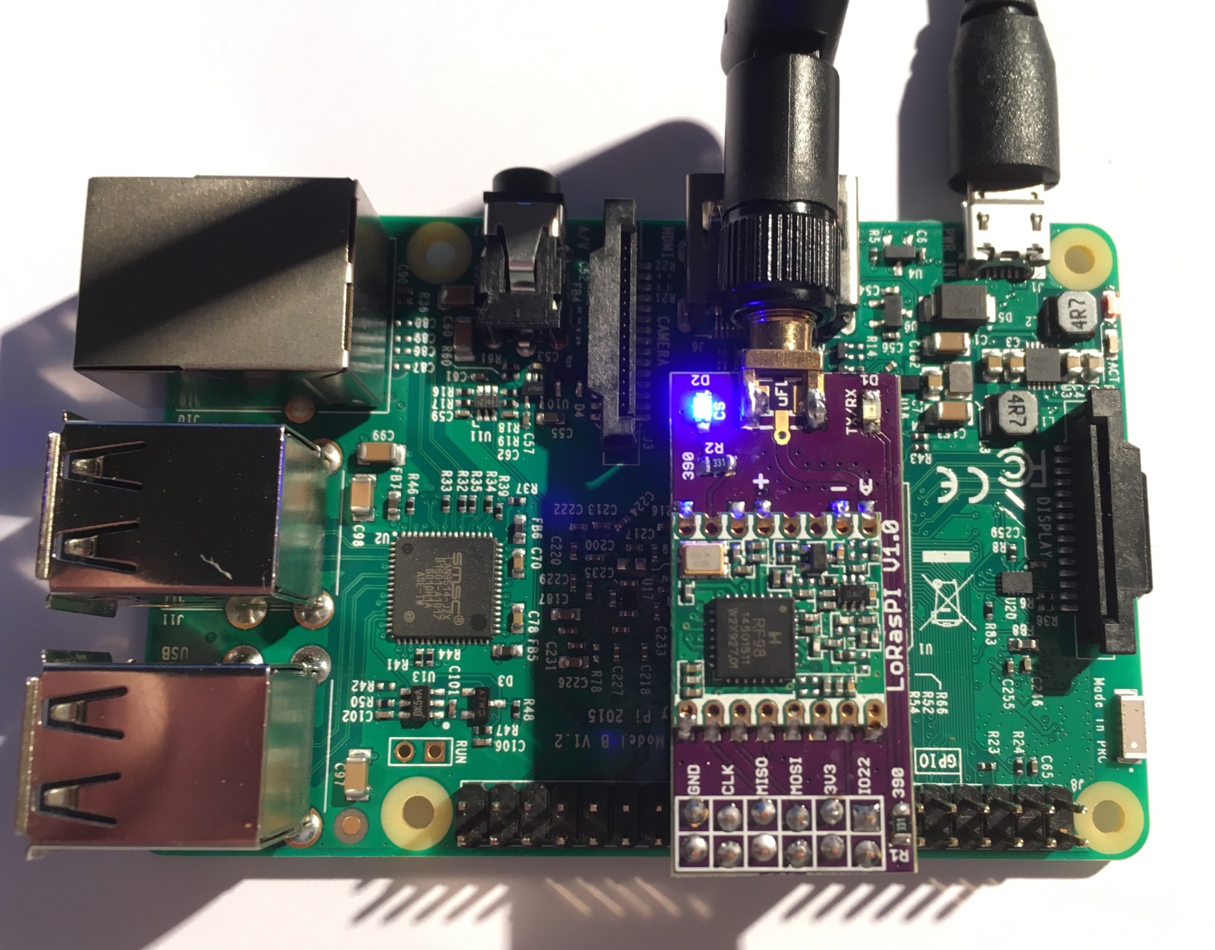
[LoRasPI][10], [Raspberry PI Lora Gateway][12], [Dragino Lora GPS HAT][13]
 - Added moteino modem setting on RF69 to be compatible with lowpowerlab RF69 configuration library
- Added possibility to work with no IRQ connected for RF69 and RF95
- for example to get one more GPIO free
- on Raspberry Pi, we do not have `attachInterrupt()` like with bcm2835 library
- Added samples for multiples Raspberry Pi boards with RF69 and RF95 modules such as
- [LoRasPI][10], simple RFM9x or RFM69HCW shield
- [iC880A or Linklabs Raspberry PI shield][11] with RFM9x or RFM69HCW onboard
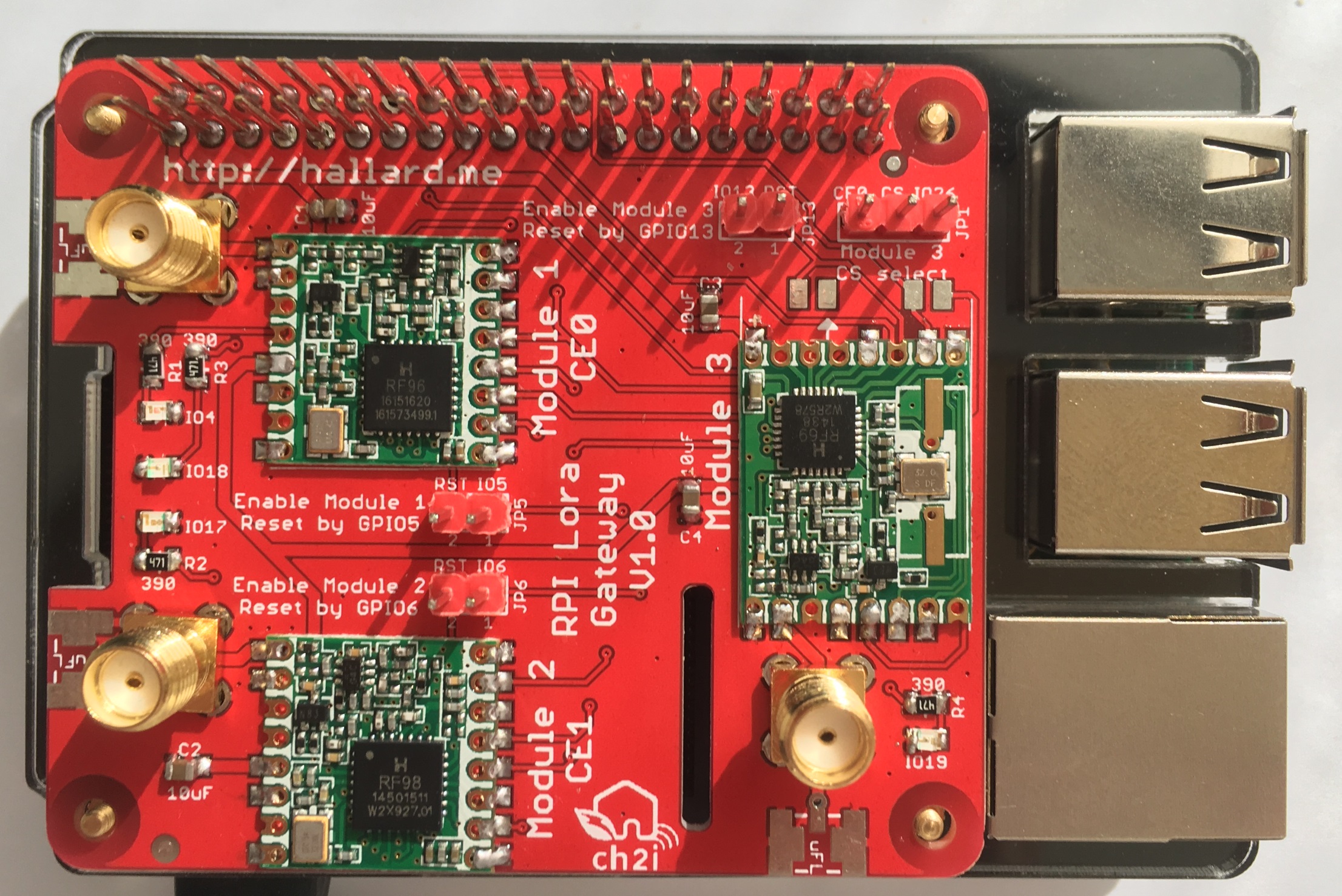
- [Raspberry PI Lora Gateway][12] with multiple RFM9x or RFM69HCW shield
- [Dragino Lora shield][13]
- Sample code are in [rf95][21], [rf69][20], [nrf24][22] and [multi_server][23], note that old sample NRF24 sample has been moved to nrf24 folder for consistency.
- Added 2 samples test tools (for Raspberry PI) do detect RF69 and RF95 modules and check IRQ rising edge
- [spi_scan][9] sample code, scan and try to detect connected modules
- [irq_test][8] sample code, check a rising edge on a GPIO
Sample code for Raspberry PI is located under [RadioHead/examples/raspi][7] folder.
### Installation on Raspberry PI
================================
Clone repository
```shell
git clone https://github.com/hallard/RadioHead
```
To avoid system hangs/instability starting with kernel 4.14, disable all GPIO kernel interrupts by adding this line to your `/boot/config.txt`:
```
dtoverlay=gpio-no-irq
```
This works around an issue with the design of the bcm2835 library and how it handles rising/falling edge detection events, but has some downsides as well. For more information, see [this issue][30] and [this discussion][31].
**Connection and pins definition**
Boards pins (Chip Select, IRQ line, Reset and LED) definition are set in the new [RadioHead/examples/raspi/RasPiBoards.h][24] file. In your code, you need to define board used and then, include the file definition like this
```cpp
// LoRasPi board
#define BOARD_LORASPI
// Now we include RasPi_Boards.h so this will expose defined
// constants with CS/IRQ/RESET/on board LED pins definition
#include "../RasPiBoards.h"
// Your code start here
#ifdef RF_RST_PIN
// Blah blah do reset line
#endif
```
Then in your code you'll have exposed RF_CS_PIN, RF_IRQ_PIN, RF_RST_PIN and RF_LED_PIN and you'll be able to do some `#ifdef RF_LED_LIN` for example. See [rf95_client][25] sample code.
So you have 3 options to define the pins you want
- The board you have is already defined so just need to define it your source code (as explained above)
- You can add your board into [RasPiBoards.h][24] and then define it your source code as above
- You can manually define pins in your code and remove the board definition and `#include "../RasPiBoards.h"`
To go further with examples :
go to example folder here spi_scan
```shell
cd RadioHead/examples/raspi/spi_scan
```
Build executable
```shell
root@pi03(rw):~/RadioHead/examples/raspi/spi_scan# make
g++ -DRASPBERRY_PI -DBCM2835_NO_DELAY_COMPATIBILITY -c -I../../.. spi_scan.c
g++ spi_scan.o -lbcm2835 -o spi_scan
root@pi03(rw):~/RadioHead/examples/raspi/spi_scan
```
And run
```shell
root@pi03(rw):~/RadioHead/examples/raspi/spi_scan# ./spi_scan
Checking register(0x42) with CS=GPIO06 => Nothing!
Checking register(0x10) with CS=GPIO06 => Nothing!
Checking register(0x42) with CS=GPIO08 => SX1276 RF95/96 (V=0x12)
Checking register(0x10) with CS=GPIO08 => Nothing!
Checking register(0x42) with CS=GPIO07 => Nothing!
Checking register(0x10) with CS=GPIO07 => Nothing!
Checking register(0x42) with CS=GPIO26 => Nothing!
Checking register(0x10) with CS=GPIO26 => Nothing!
```
And voila! with [LoRasPi][10] board RFM95 dedected on SPI with GPIO8 (CE0)
If I'm doing same test with [PI Lora Gateway][12] with 2 RFM95 (one 433MHz and one 868MHz) and one RFMHW69 433MHz on board like this
Here are the results when trying to detect the onboard modules:
```shell
root@pi01(rw):~/RadioHead/examples/raspi/spi_scan# ./spi_scan
Checking register(0x42) with CS=GPIO06 => Nothing!
Checking register(0x10) with CS=GPIO06 => Nothing!
Checking register(0x42) with CS=GPIO08 => SX1276 RF95/96 (V=0x12)
Checking register(0x10) with CS=GPIO08 => Nothing!
Checking register(0x42) with CS=GPIO07 => SX1276 RF95/96 (V=0x12)
Checking register(0x10) with CS=GPIO07 => Nothing!
Checking register(0x42) with CS=GPIO26 => Unknown (V=0x01)
Checking register(0x10) with CS=GPIO26 => SX1231 RFM69 (V=0x24)
```
Voila! 3 modules are seen, now let's try listenning packets with PI Lora [Gateway][12].
My setup has another Raspberry Pi with RFM95 868MHZ [LoRasPI][10] shield running [`rf95_client`][25] sample and some [ULPnode][6] prototypes always running with on board RFM69 configured as Group ID 69 on 433MHz. I don't have a Lora 433MHz sender running so we won't receive anything on this one.
Here the results starting from scratch
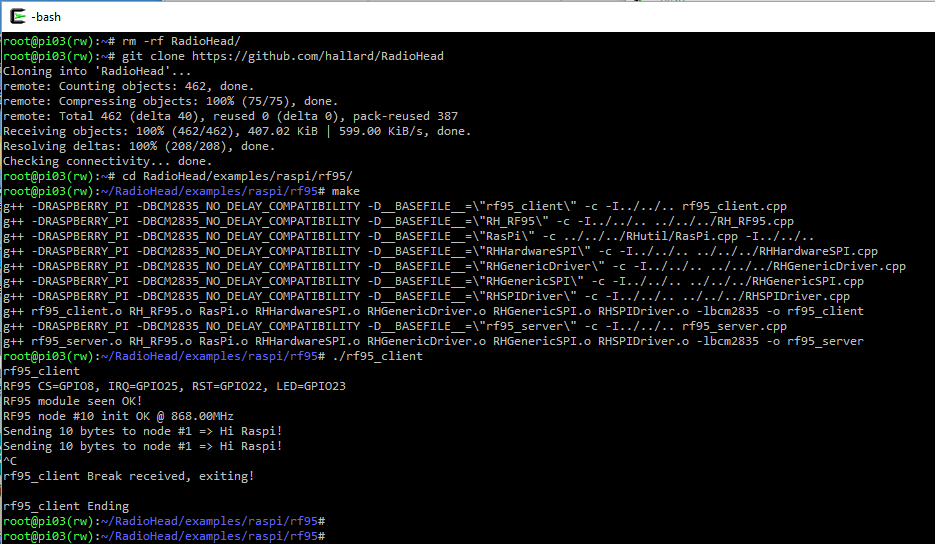
**Client side**
- Added moteino modem setting on RF69 to be compatible with lowpowerlab RF69 configuration library
- Added possibility to work with no IRQ connected for RF69 and RF95
- for example to get one more GPIO free
- on Raspberry Pi, we do not have `attachInterrupt()` like with bcm2835 library
- Added samples for multiples Raspberry Pi boards with RF69 and RF95 modules such as
- [LoRasPI][10], simple RFM9x or RFM69HCW shield
- [iC880A or Linklabs Raspberry PI shield][11] with RFM9x or RFM69HCW onboard
- [Raspberry PI Lora Gateway][12] with multiple RFM9x or RFM69HCW shield
- [Dragino Lora shield][13]
- Sample code are in [rf95][21], [rf69][20], [nrf24][22] and [multi_server][23], note that old sample NRF24 sample has been moved to nrf24 folder for consistency.
- Added 2 samples test tools (for Raspberry PI) do detect RF69 and RF95 modules and check IRQ rising edge
- [spi_scan][9] sample code, scan and try to detect connected modules
- [irq_test][8] sample code, check a rising edge on a GPIO
Sample code for Raspberry PI is located under [RadioHead/examples/raspi][7] folder.
### Installation on Raspberry PI
================================
Clone repository
```shell
git clone https://github.com/hallard/RadioHead
```
To avoid system hangs/instability starting with kernel 4.14, disable all GPIO kernel interrupts by adding this line to your `/boot/config.txt`:
```
dtoverlay=gpio-no-irq
```
This works around an issue with the design of the bcm2835 library and how it handles rising/falling edge detection events, but has some downsides as well. For more information, see [this issue][30] and [this discussion][31].
**Connection and pins definition**
Boards pins (Chip Select, IRQ line, Reset and LED) definition are set in the new [RadioHead/examples/raspi/RasPiBoards.h][24] file. In your code, you need to define board used and then, include the file definition like this
```cpp
// LoRasPi board
#define BOARD_LORASPI
// Now we include RasPi_Boards.h so this will expose defined
// constants with CS/IRQ/RESET/on board LED pins definition
#include "../RasPiBoards.h"
// Your code start here
#ifdef RF_RST_PIN
// Blah blah do reset line
#endif
```
Then in your code you'll have exposed RF_CS_PIN, RF_IRQ_PIN, RF_RST_PIN and RF_LED_PIN and you'll be able to do some `#ifdef RF_LED_LIN` for example. See [rf95_client][25] sample code.
So you have 3 options to define the pins you want
- The board you have is already defined so just need to define it your source code (as explained above)
- You can add your board into [RasPiBoards.h][24] and then define it your source code as above
- You can manually define pins in your code and remove the board definition and `#include "../RasPiBoards.h"`
To go further with examples :
go to example folder here spi_scan
```shell
cd RadioHead/examples/raspi/spi_scan
```
Build executable
```shell
root@pi03(rw):~/RadioHead/examples/raspi/spi_scan# make
g++ -DRASPBERRY_PI -DBCM2835_NO_DELAY_COMPATIBILITY -c -I../../.. spi_scan.c
g++ spi_scan.o -lbcm2835 -o spi_scan
root@pi03(rw):~/RadioHead/examples/raspi/spi_scan
```
And run
```shell
root@pi03(rw):~/RadioHead/examples/raspi/spi_scan# ./spi_scan
Checking register(0x42) with CS=GPIO06 => Nothing!
Checking register(0x10) with CS=GPIO06 => Nothing!
Checking register(0x42) with CS=GPIO08 => SX1276 RF95/96 (V=0x12)
Checking register(0x10) with CS=GPIO08 => Nothing!
Checking register(0x42) with CS=GPIO07 => Nothing!
Checking register(0x10) with CS=GPIO07 => Nothing!
Checking register(0x42) with CS=GPIO26 => Nothing!
Checking register(0x10) with CS=GPIO26 => Nothing!
```
And voila! with [LoRasPi][10] board RFM95 dedected on SPI with GPIO8 (CE0)
If I'm doing same test with [PI Lora Gateway][12] with 2 RFM95 (one 433MHz and one 868MHz) and one RFMHW69 433MHz on board like this
Here are the results when trying to detect the onboard modules:
```shell
root@pi01(rw):~/RadioHead/examples/raspi/spi_scan# ./spi_scan
Checking register(0x42) with CS=GPIO06 => Nothing!
Checking register(0x10) with CS=GPIO06 => Nothing!
Checking register(0x42) with CS=GPIO08 => SX1276 RF95/96 (V=0x12)
Checking register(0x10) with CS=GPIO08 => Nothing!
Checking register(0x42) with CS=GPIO07 => SX1276 RF95/96 (V=0x12)
Checking register(0x10) with CS=GPIO07 => Nothing!
Checking register(0x42) with CS=GPIO26 => Unknown (V=0x01)
Checking register(0x10) with CS=GPIO26 => SX1231 RFM69 (V=0x24)
```
Voila! 3 modules are seen, now let's try listenning packets with PI Lora [Gateway][12].
My setup has another Raspberry Pi with RFM95 868MHZ [LoRasPI][10] shield running [`rf95_client`][25] sample and some [ULPnode][6] prototypes always running with on board RFM69 configured as Group ID 69 on 433MHz. I don't have a Lora 433MHz sender running so we won't receive anything on this one.
Here the results starting from scratch
**Client side**
 **multi server side**
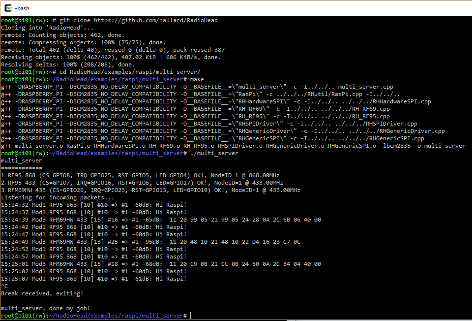 It works!
### Difference with original Author repo
========================================
Due to easier maintenance to keep in sync with original author lib, I've got 2 repo:
- My master one (this one) https://github.com/hallard/RadioHead that is the one you need if you want to use my projects or lib added features.
- The one above has been forked to https://github.com/ch2i/RadioHead where I put the original version released by the author.
Like this, I can do Pull Request from [ch2i][4] to [hallard][1] to add new features added by the author to my version. This mean that this [one][4] is just a github copy version of the latest original done by Mike, I don't do any change on this one. I know it's not the best way, but I didn't found a better solution for now, if you have better idea, just let me know.
[1]: https://github.com/hallard/RadioHead
[2]: https://hallard.me
[3]: http://www.airspayce.com/mikem/arduino/RadioHead/
[4]: http://www.airspayce.com/mikem/arduino/RadioHead/RadioHead-1.67.zip
[5]: https://github.com/ch2i/RadioHead
[6]: http://hallard.me/category/ulpnode/
[7]: https://github.com/hallard/RadioHead/tree/master/examples/raspi
[8]: https://github.com/hallard/RadioHead/tree/master/examples/raspi/irq_test
[9]: https://github.com/hallard/RadioHead/tree/master/examples/raspi/spi_scan
[10]: https://github.com/hallard/LoRasPI
[11]: https://github.com/ch2i/iC880A-Raspberry-PI
[12]: https://github.com/hallard/RPI-Lora-Gateway
[13]: https://github.com/dragino/Lora
[20]: https://github.com/hallard/RadioHead/tree/master/examples/raspi/rf69
[21]: https://github.com/hallard/RadioHead/tree/master/examples/raspi/rf95
[22]: https://github.com/hallard/RadioHead/tree/master/examples/raspi/nrf24
[23]: https://github.com/hallard/RadioHead/tree/master/examples/raspi/multi_server
[24]: https://github.com/hallard/RadioHead/tree/master/examples/raspi/RasPiBoards.h
[25]: https://github.com/hallard/RadioHead/tree/master/examples/raspi/rf95/rf95_client.cpp
[30]: https://github.com/raspberrypi/linux/issues/2550
[31]: https://groups.google.com/forum/#!topic/bcm2835/Y3D1mmp6vew
================================================
FILE: RHCRC.cpp
================================================
/* Copyright (c) 2002, 2003, 2004 Marek Michalkiewicz
Copyright (c) 2005, 2007 Joerg Wunsch
All rights reserved.
Redistribution and use in source and binary forms, with or without
modification, are permitted provided that the following conditions are met:
* Redistributions of source code must retain the above copyright
notice, this list of conditions and the following disclaimer.
* Redistributions in binary form must reproduce the above copyright
notice, this list of conditions and the following disclaimer in
the documentation and/or other materials provided with the
distribution.
* Neither the name of the copyright holders nor the names of
contributors may be used to endorse or promote products derived
from this software without specific prior written permission.
THIS SOFTWARE IS PROVIDED BY THE COPYRIGHT HOLDERS AND CONTRIBUTORS "AS IS"
AND ANY EXPRESS OR IMPLIED WARRANTIES, INCLUDING, BUT NOT LIMITED TO, THE
IMPLIED WARRANTIES OF MERCHANTABILITY AND FITNESS FOR A PARTICULAR PURPOSE
ARE DISCLAIMED. IN NO EVENT SHALL THE COPYRIGHT OWNER OR CONTRIBUTORS BE
LIABLE FOR ANY DIRECT, INDIRECT, INCIDENTAL, SPECIAL, EXEMPLARY, OR
CONSEQUENTIAL DAMAGES (INCLUDING, BUT NOT LIMITED TO, PROCUREMENT OF
SUBSTITUTE GOODS OR SERVICES; LOSS OF USE, DATA, OR PROFITS; OR BUSINESS
INTERRUPTION) HOWEVER CAUSED AND ON ANY THEORY OF LIABILITY, WHETHER IN
CONTRACT, STRICT LIABILITY, OR TORT (INCLUDING NEGLIGENCE OR OTHERWISE)
ARISING IN ANY WAY OUT OF THE USE OF THIS SOFTWARE, EVEN IF ADVISED OF THE
POSSIBILITY OF SUCH DAMAGE. */
// Port to Energia / MPS430 by Yannick DEVOS XV4Y - (c) 2013
// http://xv4y.radioclub.asia/
//
// Adapted to RadioHead use by Mike McCauley 2014
// This is to prevent name collisions with other similar library functions
// and to provide a consistent API amonng all processors
//
/* $Id: RHCRC.cpp,v 1.1 2014/06/24 02:40:12 mikem Exp $ */
#include
#define lo8(x) ((x)&0xff)
#define hi8(x) ((x)>>8)
uint16_t RHcrc16_update(uint16_t crc, uint8_t a)
{
int i;
crc ^= a;
for (i = 0; i < 8; ++i)
{
if (crc & 1)
crc = (crc >> 1) ^ 0xA001;
else
crc = (crc >> 1);
}
return crc;
}
uint16_t RHcrc_xmodem_update (uint16_t crc, uint8_t data)
{
int i;
crc = crc ^ ((uint16_t)data << 8);
for (i=0; i<8; i++)
{
if (crc & 0x8000)
crc = (crc << 1) ^ 0x1021;
else
crc <<= 1;
}
return crc;
}
uint16_t RHcrc_ccitt_update (uint16_t crc, uint8_t data)
{
data ^= lo8 (crc);
data ^= data << 4;
return ((((uint16_t)data << 8) | hi8 (crc)) ^ (uint8_t)(data >> 4)
^ ((uint16_t)data << 3));
}
uint8_t RHcrc_ibutton_update(uint8_t crc, uint8_t data)
{
uint8_t i;
crc = crc ^ data;
for (i = 0; i < 8; i++)
{
if (crc & 0x01)
crc = (crc >> 1) ^ 0x8C;
else
crc >>= 1;
}
return crc;
}
================================================
FILE: RHCRC.h
================================================
// RHCRC.h
//
// Definitions for RadioHead compatible CRC outines.
//
// These routines originally derived from Arduino source code. See RHCRC.cpp
// for copyright information
// $Id: RHCRC.h,v 1.1 2014/06/24 02:40:12 mikem Exp $
#ifndef RHCRC_h
#define RHCRC_h
#include
extern uint16_t RHcrc16_update(uint16_t crc, uint8_t a);
extern uint16_t RHcrc_xmodem_update (uint16_t crc, uint8_t data);
extern uint16_t RHcrc_ccitt_update (uint16_t crc, uint8_t data);
extern uint8_t RHcrc_ibutton_update(uint8_t crc, uint8_t data);
#endif
================================================
FILE: RHDatagram.cpp
================================================
// RHDatagram.cpp
//
// Copyright (C) 2011 Mike McCauley
// $Id: RHDatagram.cpp,v 1.6 2014/05/23 02:20:17 mikem Exp $
#include
RHDatagram::RHDatagram(RHGenericDriver& driver, uint8_t thisAddress)
:
_driver(driver),
_thisAddress(thisAddress)
{
}
////////////////////////////////////////////////////////////////////
// Public methods
bool RHDatagram::init()
{
bool ret = _driver.init();
if (ret)
setThisAddress(_thisAddress);
return ret;
}
void RHDatagram::setThisAddress(uint8_t thisAddress)
{
_driver.setThisAddress(thisAddress);
// Use this address in the transmitted FROM header
setHeaderFrom(thisAddress);
_thisAddress = thisAddress;
}
bool RHDatagram::sendto(uint8_t* buf, uint8_t len, uint8_t address)
{
setHeaderTo(address);
return _driver.send(buf, len);
}
bool RHDatagram::recvfrom(uint8_t* buf, uint8_t* len, uint8_t* from, uint8_t* to, uint8_t* id, uint8_t* flags)
{
if (_driver.recv(buf, len))
{
if (from) *from = headerFrom();
if (to) *to = headerTo();
if (id) *id = headerId();
if (flags) *flags = headerFlags();
return true;
}
return false;
}
bool RHDatagram::available()
{
return _driver.available();
}
void RHDatagram::waitAvailable()
{
_driver.waitAvailable();
}
bool RHDatagram::waitPacketSent()
{
return _driver.waitPacketSent();
}
bool RHDatagram::waitPacketSent(uint16_t timeout)
{
return _driver.waitPacketSent(timeout);
}
bool RHDatagram::waitAvailableTimeout(uint16_t timeout)
{
return _driver.waitAvailableTimeout(timeout);
}
uint8_t RHDatagram::thisAddress()
{
return _thisAddress;
}
void RHDatagram::setHeaderTo(uint8_t to)
{
_driver.setHeaderTo(to);
}
void RHDatagram::setHeaderFrom(uint8_t from)
{
_driver.setHeaderFrom(from);
}
void RHDatagram::setHeaderId(uint8_t id)
{
_driver.setHeaderId(id);
}
void RHDatagram::setHeaderFlags(uint8_t set, uint8_t clear)
{
_driver.setHeaderFlags(set, clear);
}
uint8_t RHDatagram::headerTo()
{
return _driver.headerTo();
}
uint8_t RHDatagram::headerFrom()
{
return _driver.headerFrom();
}
uint8_t RHDatagram::headerId()
{
return _driver.headerId();
}
uint8_t RHDatagram::headerFlags()
{
return _driver.headerFlags();
}
================================================
FILE: RHDatagram.h
================================================
// RHDatagram.h
// Author: Mike McCauley (mikem@airspayce.com)
// Copyright (C) 2011 Mike McCauley
// $Id: RHDatagram.h,v 1.14 2015/08/12 23:18:51 mikem Exp $
#ifndef RHDatagram_h
#define RHDatagram_h
#include
// This is the maximum possible message size for radios supported by RadioHead.
// Not all radios support this length, and many are much smaller
#define RH_MAX_MESSAGE_LEN 255
/////////////////////////////////////////////////////////////////////
/// \class RHDatagram RHDatagram.h
/// \brief Manager class for addressed, unreliable messages
///
/// Every RHDatagram node has an 8 bit address (defaults to 0).
/// Addresses (DEST and SRC) are 8 bit integers with an address of RH_BROADCAST_ADDRESS (0xff)
/// reserved for broadcast.
///
/// \par Media Access Strategy
///
/// RHDatagram and the underlying drivers always transmit as soon as sendto() is called.
///
/// \par Message Lengths
///
/// Not all Radio drivers supported by RadioHead can handle the same message lengths. Some radios can handle
/// up to 255 octets, and some as few as 28. If you attempt to send a message that is too long for
/// the underlying driver, sendTo() will return false and will not transmit the message.
/// It is the programmers responsibility to make
/// sure that messages passed to sendto() do not exceed the capability of the radio. You can use the
/// *_MAX_MESSAGE_LENGTH definitions or driver->maxMessageLength() to help.
///
/// \par Headers
///
/// Each message sent and received by a RadioHead driver includes 4 headers:
It works!
### Difference with original Author repo
========================================
Due to easier maintenance to keep in sync with original author lib, I've got 2 repo:
- My master one (this one) https://github.com/hallard/RadioHead that is the one you need if you want to use my projects or lib added features.
- The one above has been forked to https://github.com/ch2i/RadioHead where I put the original version released by the author.
Like this, I can do Pull Request from [ch2i][4] to [hallard][1] to add new features added by the author to my version. This mean that this [one][4] is just a github copy version of the latest original done by Mike, I don't do any change on this one. I know it's not the best way, but I didn't found a better solution for now, if you have better idea, just let me know.
[1]: https://github.com/hallard/RadioHead
[2]: https://hallard.me
[3]: http://www.airspayce.com/mikem/arduino/RadioHead/
[4]: http://www.airspayce.com/mikem/arduino/RadioHead/RadioHead-1.67.zip
[5]: https://github.com/ch2i/RadioHead
[6]: http://hallard.me/category/ulpnode/
[7]: https://github.com/hallard/RadioHead/tree/master/examples/raspi
[8]: https://github.com/hallard/RadioHead/tree/master/examples/raspi/irq_test
[9]: https://github.com/hallard/RadioHead/tree/master/examples/raspi/spi_scan
[10]: https://github.com/hallard/LoRasPI
[11]: https://github.com/ch2i/iC880A-Raspberry-PI
[12]: https://github.com/hallard/RPI-Lora-Gateway
[13]: https://github.com/dragino/Lora
[20]: https://github.com/hallard/RadioHead/tree/master/examples/raspi/rf69
[21]: https://github.com/hallard/RadioHead/tree/master/examples/raspi/rf95
[22]: https://github.com/hallard/RadioHead/tree/master/examples/raspi/nrf24
[23]: https://github.com/hallard/RadioHead/tree/master/examples/raspi/multi_server
[24]: https://github.com/hallard/RadioHead/tree/master/examples/raspi/RasPiBoards.h
[25]: https://github.com/hallard/RadioHead/tree/master/examples/raspi/rf95/rf95_client.cpp
[30]: https://github.com/raspberrypi/linux/issues/2550
[31]: https://groups.google.com/forum/#!topic/bcm2835/Y3D1mmp6vew
================================================
FILE: RHCRC.cpp
================================================
/* Copyright (c) 2002, 2003, 2004 Marek Michalkiewicz
Copyright (c) 2005, 2007 Joerg Wunsch
All rights reserved.
Redistribution and use in source and binary forms, with or without
modification, are permitted provided that the following conditions are met:
* Redistributions of source code must retain the above copyright
notice, this list of conditions and the following disclaimer.
* Redistributions in binary form must reproduce the above copyright
notice, this list of conditions and the following disclaimer in
the documentation and/or other materials provided with the
distribution.
* Neither the name of the copyright holders nor the names of
contributors may be used to endorse or promote products derived
from this software without specific prior written permission.
THIS SOFTWARE IS PROVIDED BY THE COPYRIGHT HOLDERS AND CONTRIBUTORS "AS IS"
AND ANY EXPRESS OR IMPLIED WARRANTIES, INCLUDING, BUT NOT LIMITED TO, THE
IMPLIED WARRANTIES OF MERCHANTABILITY AND FITNESS FOR A PARTICULAR PURPOSE
ARE DISCLAIMED. IN NO EVENT SHALL THE COPYRIGHT OWNER OR CONTRIBUTORS BE
LIABLE FOR ANY DIRECT, INDIRECT, INCIDENTAL, SPECIAL, EXEMPLARY, OR
CONSEQUENTIAL DAMAGES (INCLUDING, BUT NOT LIMITED TO, PROCUREMENT OF
SUBSTITUTE GOODS OR SERVICES; LOSS OF USE, DATA, OR PROFITS; OR BUSINESS
INTERRUPTION) HOWEVER CAUSED AND ON ANY THEORY OF LIABILITY, WHETHER IN
CONTRACT, STRICT LIABILITY, OR TORT (INCLUDING NEGLIGENCE OR OTHERWISE)
ARISING IN ANY WAY OUT OF THE USE OF THIS SOFTWARE, EVEN IF ADVISED OF THE
POSSIBILITY OF SUCH DAMAGE. */
// Port to Energia / MPS430 by Yannick DEVOS XV4Y - (c) 2013
// http://xv4y.radioclub.asia/
//
// Adapted to RadioHead use by Mike McCauley 2014
// This is to prevent name collisions with other similar library functions
// and to provide a consistent API amonng all processors
//
/* $Id: RHCRC.cpp,v 1.1 2014/06/24 02:40:12 mikem Exp $ */
#include
#define lo8(x) ((x)&0xff)
#define hi8(x) ((x)>>8)
uint16_t RHcrc16_update(uint16_t crc, uint8_t a)
{
int i;
crc ^= a;
for (i = 0; i < 8; ++i)
{
if (crc & 1)
crc = (crc >> 1) ^ 0xA001;
else
crc = (crc >> 1);
}
return crc;
}
uint16_t RHcrc_xmodem_update (uint16_t crc, uint8_t data)
{
int i;
crc = crc ^ ((uint16_t)data << 8);
for (i=0; i<8; i++)
{
if (crc & 0x8000)
crc = (crc << 1) ^ 0x1021;
else
crc <<= 1;
}
return crc;
}
uint16_t RHcrc_ccitt_update (uint16_t crc, uint8_t data)
{
data ^= lo8 (crc);
data ^= data << 4;
return ((((uint16_t)data << 8) | hi8 (crc)) ^ (uint8_t)(data >> 4)
^ ((uint16_t)data << 3));
}
uint8_t RHcrc_ibutton_update(uint8_t crc, uint8_t data)
{
uint8_t i;
crc = crc ^ data;
for (i = 0; i < 8; i++)
{
if (crc & 0x01)
crc = (crc >> 1) ^ 0x8C;
else
crc >>= 1;
}
return crc;
}
================================================
FILE: RHCRC.h
================================================
// RHCRC.h
//
// Definitions for RadioHead compatible CRC outines.
//
// These routines originally derived from Arduino source code. See RHCRC.cpp
// for copyright information
// $Id: RHCRC.h,v 1.1 2014/06/24 02:40:12 mikem Exp $
#ifndef RHCRC_h
#define RHCRC_h
#include
extern uint16_t RHcrc16_update(uint16_t crc, uint8_t a);
extern uint16_t RHcrc_xmodem_update (uint16_t crc, uint8_t data);
extern uint16_t RHcrc_ccitt_update (uint16_t crc, uint8_t data);
extern uint8_t RHcrc_ibutton_update(uint8_t crc, uint8_t data);
#endif
================================================
FILE: RHDatagram.cpp
================================================
// RHDatagram.cpp
//
// Copyright (C) 2011 Mike McCauley
// $Id: RHDatagram.cpp,v 1.6 2014/05/23 02:20:17 mikem Exp $
#include
RHDatagram::RHDatagram(RHGenericDriver& driver, uint8_t thisAddress)
:
_driver(driver),
_thisAddress(thisAddress)
{
}
////////////////////////////////////////////////////////////////////
// Public methods
bool RHDatagram::init()
{
bool ret = _driver.init();
if (ret)
setThisAddress(_thisAddress);
return ret;
}
void RHDatagram::setThisAddress(uint8_t thisAddress)
{
_driver.setThisAddress(thisAddress);
// Use this address in the transmitted FROM header
setHeaderFrom(thisAddress);
_thisAddress = thisAddress;
}
bool RHDatagram::sendto(uint8_t* buf, uint8_t len, uint8_t address)
{
setHeaderTo(address);
return _driver.send(buf, len);
}
bool RHDatagram::recvfrom(uint8_t* buf, uint8_t* len, uint8_t* from, uint8_t* to, uint8_t* id, uint8_t* flags)
{
if (_driver.recv(buf, len))
{
if (from) *from = headerFrom();
if (to) *to = headerTo();
if (id) *id = headerId();
if (flags) *flags = headerFlags();
return true;
}
return false;
}
bool RHDatagram::available()
{
return _driver.available();
}
void RHDatagram::waitAvailable()
{
_driver.waitAvailable();
}
bool RHDatagram::waitPacketSent()
{
return _driver.waitPacketSent();
}
bool RHDatagram::waitPacketSent(uint16_t timeout)
{
return _driver.waitPacketSent(timeout);
}
bool RHDatagram::waitAvailableTimeout(uint16_t timeout)
{
return _driver.waitAvailableTimeout(timeout);
}
uint8_t RHDatagram::thisAddress()
{
return _thisAddress;
}
void RHDatagram::setHeaderTo(uint8_t to)
{
_driver.setHeaderTo(to);
}
void RHDatagram::setHeaderFrom(uint8_t from)
{
_driver.setHeaderFrom(from);
}
void RHDatagram::setHeaderId(uint8_t id)
{
_driver.setHeaderId(id);
}
void RHDatagram::setHeaderFlags(uint8_t set, uint8_t clear)
{
_driver.setHeaderFlags(set, clear);
}
uint8_t RHDatagram::headerTo()
{
return _driver.headerTo();
}
uint8_t RHDatagram::headerFrom()
{
return _driver.headerFrom();
}
uint8_t RHDatagram::headerId()
{
return _driver.headerId();
}
uint8_t RHDatagram::headerFlags()
{
return _driver.headerFlags();
}
================================================
FILE: RHDatagram.h
================================================
// RHDatagram.h
// Author: Mike McCauley (mikem@airspayce.com)
// Copyright (C) 2011 Mike McCauley
// $Id: RHDatagram.h,v 1.14 2015/08/12 23:18:51 mikem Exp $
#ifndef RHDatagram_h
#define RHDatagram_h
#include
// This is the maximum possible message size for radios supported by RadioHead.
// Not all radios support this length, and many are much smaller
#define RH_MAX_MESSAGE_LEN 255
/////////////////////////////////////////////////////////////////////
/// \class RHDatagram RHDatagram.h
/// \brief Manager class for addressed, unreliable messages
///
/// Every RHDatagram node has an 8 bit address (defaults to 0).
/// Addresses (DEST and SRC) are 8 bit integers with an address of RH_BROADCAST_ADDRESS (0xff)
/// reserved for broadcast.
///
/// \par Media Access Strategy
///
/// RHDatagram and the underlying drivers always transmit as soon as sendto() is called.
///
/// \par Message Lengths
///
/// Not all Radio drivers supported by RadioHead can handle the same message lengths. Some radios can handle
/// up to 255 octets, and some as few as 28. If you attempt to send a message that is too long for
/// the underlying driver, sendTo() will return false and will not transmit the message.
/// It is the programmers responsibility to make
/// sure that messages passed to sendto() do not exceed the capability of the radio. You can use the
/// *_MAX_MESSAGE_LENGTH definitions or driver->maxMessageLength() to help.
///
/// \par Headers
///
/// Each message sent and received by a RadioHead driver includes 4 headers:
/// \b TO The node address that the message is being sent to (broadcast RH_BROADCAST_ADDRESS (255) is permitted)
/// \b FROM The node address of the sending node
/// \b ID A message ID, distinct (over short time scales) for each message sent by a particilar node
/// \b FLAGS A bitmask of flags. The most significant 4 bits are reserved for use by RadioHead. The least
/// significant 4 bits are reserved for applications.
///
class RHDatagram
{
public:
/// Constructor.
/// \param[in] driver The RadioHead driver to use to transport messages.
/// \param[in] thisAddress The address to assign to this node. Defaults to 0
RHDatagram(RHGenericDriver& driver, uint8_t thisAddress = 0);
/// Initialise this instance and the
/// driver connected to it.
bool init();
/// Sets the address of this node. Defaults to 0.
/// This will be used to set the FROM address of all messages sent by this node.
/// In a conventional multinode system, all nodes will have a unique address
/// (which you could store in EEPROM).
/// \param[in] thisAddress The address of this node
void setThisAddress(uint8_t thisAddress);
/// Sends a message to the node(s) with the given address
/// RH_BROADCAST_ADDRESS is a valid address which will cause the message
/// to be accepted by all RHDatagram nodes within range.
/// \param[in] buf Pointer to the binary message to send
/// \param[in] len Number of octets to send (> 0)
/// \param[in] address The address to send the message to.
/// \return true if the message not too loing fot eh driver, and the message was transmitted.
bool sendto(uint8_t* buf, uint8_t len, uint8_t address);
/// Turns the receiver on if it not already on.
/// If there is a valid message available for this node, copy it to buf and return true
/// The SRC address is placed in *from if present and not NULL.
/// The DEST address is placed in *to if present and not NULL.
/// If a message is copied, *len is set to the length.
/// You should be sure to call this function frequently enough to not miss any messages
/// It is recommended that you call it in your main loop.
/// \param[in] buf Location to copy the received message
/// \param[in,out] len Pointer to available space in buf. Set to the actual number of octets copied.
/// \param[in] from If present and not NULL, the referenced uint8_t will be set to the FROM address
/// \param[in] to If present and not NULL, the referenced uint8_t will be set to the TO address
/// \param[in] id If present and not NULL, the referenced uint8_t will be set to the ID
/// \param[in] flags If present and not NULL, the referenced uint8_t will be set to the FLAGS
/// (not just those addressed to this node).
/// \return true if a valid message was copied to buf
bool recvfrom(uint8_t* buf, uint8_t* len, uint8_t* from = NULL, uint8_t* to = NULL, uint8_t* id = NULL, uint8_t* flags = NULL);
/// Tests whether a new message is available
/// from the Driver.
/// On most drivers, this will also put the Driver into RHModeRx mode until
/// a message is actually received bythe transport, when it will be returned to RHModeIdle.
/// This can be called multiple times in a timeout loop.
/// \return true if a new, complete, error-free uncollected message is available to be retreived by recv()
bool available();
/// Starts the Driver receiver and blocks until a valid received
/// message is available.
void waitAvailable();
/// Blocks until the transmitter
/// is no longer transmitting.
bool waitPacketSent();
/// Blocks until the transmitter is no longer transmitting.
/// or until the timeout occuers, whichever happens first
/// \param[in] timeout Maximum time to wait in milliseconds.
/// \return true if the radio completed transmission within the timeout period. False if it timed out.
bool waitPacketSent(uint16_t timeout);
/// Starts the Driver receiver and blocks until a received message is available or a timeout
/// \param[in] timeout Maximum time to wait in milliseconds.
/// \return true if a message is available
bool waitAvailableTimeout(uint16_t timeout);
/// Sets the TO header to be sent in all subsequent messages
/// \param[in] to The new TO header value
void setHeaderTo(uint8_t to);
/// Sets the FROM header to be sent in all subsequent messages
/// \param[in] from The new FROM header value
void setHeaderFrom(uint8_t from);
/// Sets the ID header to be sent in all subsequent messages
/// \param[in] id The new ID header value
void setHeaderId(uint8_t id);
/// Sets and clears bits in the FLAGS header to be sent in all subsequent messages
/// \param[in] set bitmask of bits to be set
/// \param[in] clear bitmask of flags to clear
void setHeaderFlags(uint8_t set, uint8_t clear = RH_FLAGS_NONE);
/// Returns the TO header of the last received message
/// \return The TO header of the most recently received message.
uint8_t headerTo();
/// Returns the FROM header of the last received message
/// \return The FROM header of the most recently received message.
uint8_t headerFrom();
/// Returns the ID header of the last received message
/// \return The ID header of the most recently received message.
uint8_t headerId();
/// Returns the FLAGS header of the last received message
/// \return The FLAGS header of the most recently received message.
uint8_t headerFlags();
/// Returns the address of this node.
/// \return The address of this node
uint8_t thisAddress();
protected:
/// The Driver we are to use
RHGenericDriver& _driver;
/// The address of this node
uint8_t _thisAddress;
};
#endif
================================================
FILE: RHGenericDriver.cpp
================================================
// RHGenericDriver.cpp
//
// Copyright (C) 2014 Mike McCauley
// $Id: RHGenericDriver.cpp,v 1.20 2017/01/12 23:58:00 mikem Exp $
#include
RHGenericDriver::RHGenericDriver()
:
_mode(RHModeInitialising),
_thisAddress(RH_BROADCAST_ADDRESS),
_txHeaderTo(RH_BROADCAST_ADDRESS),
_txHeaderFrom(RH_BROADCAST_ADDRESS),
_txHeaderId(0),
_txHeaderFlags(0),
_rxBad(0),
_rxGood(0),
_txGood(0),
_cad_timeout(0)
{
}
bool RHGenericDriver::init()
{
return true;
}
// Blocks until a valid message is received
void RHGenericDriver::waitAvailable()
{
while (!available())
YIELD;
}
// Blocks until a valid message is received or timeout expires
// Return true if there is a message available
// Works correctly even on millis() rollover
bool RHGenericDriver::waitAvailableTimeout(uint16_t timeout)
{
unsigned long starttime = millis();
while ((millis() - starttime) < timeout)
{
if (available())
{
return true;
}
YIELD;
}
return false;
}
bool RHGenericDriver::waitPacketSent()
{
while (_mode == RHModeTx)
YIELD; // Wait for any previous transmit to finish
return true;
}
bool RHGenericDriver::waitPacketSent(uint16_t timeout)
{
unsigned long starttime = millis();
while ((millis() - starttime) < timeout)
{
if (_mode != RHModeTx) // Any previous transmit finished?
return true;
YIELD;
}
return false;
}
// Wait until no channel activity detected or timeout
bool RHGenericDriver::waitCAD()
{
if (!_cad_timeout)
return true;
// Wait for any channel activity to finish or timeout
// Sophisticated DCF function...
// DCF : BackoffTime = random() x aSlotTime
// 100 - 1000 ms
// 10 sec timeout
unsigned long t = millis();
while (isChannelActive())
{
if (millis() - t > _cad_timeout)
return false;
delay(random(1, 10) * 100); // Should these values be configurable? Macros?
}
return true;
}
// subclasses are expected to override if CAD is available for that radio
bool RHGenericDriver::isChannelActive()
{
return false;
}
void RHGenericDriver::setPromiscuous(bool promiscuous)
{
_promiscuous = promiscuous;
}
void RHGenericDriver::setThisAddress(uint8_t address)
{
_thisAddress = address;
}
void RHGenericDriver::setHeaderTo(uint8_t to)
{
_txHeaderTo = to;
}
void RHGenericDriver::setHeaderFrom(uint8_t from)
{
_txHeaderFrom = from;
}
void RHGenericDriver::setHeaderId(uint8_t id)
{
_txHeaderId = id;
}
void RHGenericDriver::setHeaderFlags(uint8_t set, uint8_t clear)
{
_txHeaderFlags &= ~clear;
_txHeaderFlags |= set;
}
uint8_t RHGenericDriver::headerTo()
{
return _rxHeaderTo;
}
uint8_t RHGenericDriver::headerFrom()
{
return _rxHeaderFrom;
}
uint8_t RHGenericDriver::headerId()
{
return _rxHeaderId;
}
uint8_t RHGenericDriver::headerFlags()
{
return _rxHeaderFlags;
}
int8_t RHGenericDriver::lastRssi()
{
return _lastRssi;
}
RHGenericDriver::RHMode RHGenericDriver::mode()
{
return _mode;
}
void RHGenericDriver::setMode(RHMode mode)
{
_mode = mode;
}
bool RHGenericDriver::sleep()
{
return false;
}
// Diagnostic help
void RHGenericDriver::printBuffer(const char* prompt, const uint8_t* buf, uint8_t len)
{
uint8_t i;
#ifdef RH_HAVE_SERIAL
Serial.println(prompt);
for (i = 0; i < len; i++)
{
if (i % 16 == 15)
Serial.println(buf[i], HEX);
else
{
Serial.print(buf[i], HEX);
Serial.print(' ');
}
}
Serial.println("");
#endif
}
uint16_t RHGenericDriver::rxBad()
{
return _rxBad;
}
uint16_t RHGenericDriver::rxGood()
{
return _rxGood;
}
uint16_t RHGenericDriver::txGood()
{
return _txGood;
}
void RHGenericDriver::setCADTimeout(unsigned long cad_timeout)
{
_cad_timeout = cad_timeout;
}
#if (RH_PLATFORM == RH_PLATFORM_ARDUINO) && defined(RH_PLATFORM_ATTINY)
// Tinycore does not have __cxa_pure_virtual, so without this we
// get linking complaints from the default code generated for pure virtual functions
extern "C" void __cxa_pure_virtual()
{
while (1);
}
#endif
================================================
FILE: RHGenericDriver.h
================================================
// RHGenericDriver.h
// Author: Mike McCauley (mikem@airspayce.com)
// Copyright (C) 2014 Mike McCauley
// $Id: RHGenericDriver.h,v 1.18 2017/01/12 23:58:00 mikem Exp $
#ifndef RHGenericDriver_h
#define RHGenericDriver_h
#include
// Defines bits of the FLAGS header reserved for use by the RadioHead library and
// the flags available for use by applications
#define RH_FLAGS_RESERVED 0xf0
#define RH_FLAGS_APPLICATION_SPECIFIC 0x0f
#define RH_FLAGS_NONE 0
// Default timeout for waitCAD() in ms
#define RH_CAD_DEFAULT_TIMEOUT 10000
/////////////////////////////////////////////////////////////////////
/// \class RHGenericDriver RHGenericDriver.h
/// \brief Abstract base class for a RadioHead driver.
///
/// This class defines the functions that must be provided by any RadioHead driver.
/// Different types of driver will implement all the abstract functions, and will perhaps override
/// other functions in this subclass, or perhaps add new functions specifically required by that driver.
/// Do not directly instantiate this class: it is only to be subclassed by driver classes.
///
/// Subclasses are expected to implement a half-duplex, unreliable, error checked, unaddressed packet transport.
/// They are expected to carry a message payload with an appropriate maximum length for the transport hardware
/// and to also carry unaltered 4 message headers: TO, FROM, ID, FLAGS
///
/// \par Headers
///
/// Each message sent and received by a RadioHead driver includes 4 headers:
/// -TO The node address that the message is being sent to (broadcast RH_BROADCAST_ADDRESS (255) is permitted)
/// -FROM The node address of the sending node
/// -ID A message ID, distinct (over short time scales) for each message sent by a particilar node
/// -FLAGS A bitmask of flags. The most significant 4 bits are reserved for use by RadioHead. The least
/// significant 4 bits are reserved for applications.
class RHGenericDriver
{
public:
/// \brief Defines different operating modes for the transport hardware
///
/// These are the different values that can be adopted by the _mode variable and
/// returned by the mode() member function,
typedef enum
{
RHModeInitialising = 0, ///< Transport is initialising. Initial default value until init() is called..
RHModeSleep, ///< Transport hardware is in low power sleep mode (if supported)
RHModeIdle, ///< Transport is idle.
RHModeTx, ///< Transport is in the process of transmitting a message.
RHModeRx, ///< Transport is in the process of receiving a message.
RHModeCad ///< Transport is in the process of detecting channel activity (if supported)
} RHMode;
/// Constructor
RHGenericDriver();
/// Initialise the Driver transport hardware and software.
/// Make sure the Driver is properly configured before calling init().
/// \return true if initialisation succeeded.
virtual bool init();
/// Tests whether a new message is available
/// from the Driver.
/// On most drivers, if there is an uncollected received message, and there is no message
/// currently bing transmitted, this will also put the Driver into RHModeRx mode until
/// a message is actually received by the transport, when it will be returned to RHModeIdle.
/// This can be called multiple times in a timeout loop.
/// \return true if a new, complete, error-free uncollected message is available to be retreived by recv().
virtual bool available() = 0;
/// Turns the receiver on if it not already on.
/// If there is a valid message available, copy it to buf and return true
/// else return false.
/// If a message is copied, *len is set to the length (Caution, 0 length messages are permitted).
/// You should be sure to call this function frequently enough to not miss any messages
/// It is recommended that you call it in your main loop.
/// \param[in] buf Location to copy the received message
/// \param[in,out] len Pointer to available space in buf. Set to the actual number of octets copied.
/// \return true if a valid message was copied to buf
virtual bool recv(uint8_t* buf, uint8_t* len) = 0;
/// Waits until any previous transmit packet is finished being transmitted with waitPacketSent().
/// Then optionally waits for Channel Activity Detection (CAD)
/// to show the channnel is clear (if the radio supports CAD) by calling waitCAD().
/// Then loads a message into the transmitter and starts the transmitter. Note that a message length
/// of 0 is NOT permitted. If the message is too long for the underlying radio technology, send() will
/// return false and will not send the message.
/// \param[in] data Array of data to be sent
/// \param[in] len Number of bytes of data to send (> 0)
/// specify the maximum time in ms to wait. If 0 (the default) do not wait for CAD before transmitting.
/// \return true if the message length was valid and it was correctly queued for transmit. Return false
/// if CAD was requested and the CAD timeout timed out before clear channel was detected.
virtual bool send(const uint8_t* data, uint8_t len) = 0;
/// Returns the maximum message length
/// available in this Driver.
/// \return The maximum legal message length
virtual uint8_t maxMessageLength() = 0;
/// Starts the receiver and blocks until a valid received
/// message is available.
virtual void waitAvailable();
/// Blocks until the transmitter
/// is no longer transmitting.
virtual bool waitPacketSent();
/// Blocks until the transmitter is no longer transmitting.
/// or until the timeout occuers, whichever happens first
/// \param[in] timeout Maximum time to wait in milliseconds.
/// \return true if the radio completed transmission within the timeout period. False if it timed out.
virtual bool waitPacketSent(uint16_t timeout);
/// Starts the receiver and blocks until a received message is available or a timeout
/// \param[in] timeout Maximum time to wait in milliseconds.
/// \return true if a message is available
virtual bool waitAvailableTimeout(uint16_t timeout);
// Bent G Christensen (bentor@gmail.com), 08/15/2016
/// Channel Activity Detection (CAD).
/// Blocks until channel activity is finished or CAD timeout occurs.
/// Uses the radio's CAD function (if supported) to detect channel activity.
/// Implements random delays of 100 to 1000ms while activity is detected and until timeout.
/// Caution: the random() function is not seeded. If you want non-deterministic behaviour, consider
/// using something like randomSeed(analogRead(A0)); in your sketch.
/// Permits the implementation of listen-before-talk mechanism (Collision Avoidance).
/// Calls the isChannelActive() member function for the radio (if supported)
/// to determine if the channel is active. If the radio does not support isChannelActive(),
/// always returns true immediately
/// \return true if the radio-specific CAD (as returned by isChannelActive())
/// shows the channel is clear within the timeout period (or the timeout period is 0), else returns false.
virtual bool waitCAD();
/// Sets the Channel Activity Detection timeout in milliseconds to be used by waitCAD().
/// The default is 0, which means do not wait for CAD detection.
/// CAD detection depends on support for isChannelActive() by your particular radio.
void setCADTimeout(unsigned long cad_timeout);
/// Determine if the currently selected radio channel is active.
/// This is expected to be subclassed by specific radios to implement their Channel Activity Detection
/// if supported. If the radio does not support CAD, returns true immediately. If a RadioHead radio
/// supports isChannelActive() it will be documented in the radio specific documentation.
/// This is called automatically by waitCAD().
/// \return true if the radio-specific CAD (as returned by override of isChannelActive()) shows the
/// current radio channel as active, else false. If there is no radio-specific CAD, returns false.
virtual bool isChannelActive();
/// Sets the address of this node. Defaults to 0xFF. Subclasses or the user may want to change this.
/// This will be used to test the adddress in incoming messages. In non-promiscuous mode,
/// only messages with a TO header the same as thisAddress or the broadcast addess (0xFF) will be accepted.
/// In promiscuous mode, all messages will be accepted regardless of the TO header.
/// In a conventional multinode system, all nodes will have a unique address
/// (which you could store in EEPROM).
/// You would normally set the header FROM address to be the same as thisAddress (though you dont have to,
/// allowing the possibilty of address spoofing).
/// \param[in] thisAddress The address of this node.
virtual void setThisAddress(uint8_t thisAddress);
/// Sets the TO header to be sent in all subsequent messages
/// \param[in] to The new TO header value
virtual void setHeaderTo(uint8_t to);
/// Sets the FROM header to be sent in all subsequent messages
/// \param[in] from The new FROM header value
virtual void setHeaderFrom(uint8_t from);
/// Sets the ID header to be sent in all subsequent messages
/// \param[in] id The new ID header value
virtual void setHeaderId(uint8_t id);
/// Sets and clears bits in the FLAGS header to be sent in all subsequent messages
/// First it clears he FLAGS according to the clear argument, then sets the flags according to the
/// set argument. The default for clear always clears the application specific flags.
/// \param[in] set bitmask of bits to be set. Flags are cleared with the clear mask before being set.
/// \param[in] clear bitmask of flags to clear. Defaults to RH_FLAGS_APPLICATION_SPECIFIC
/// which clears the application specific flags, resulting in new application specific flags
/// identical to the set.
virtual void setHeaderFlags(uint8_t set, uint8_t clear = RH_FLAGS_APPLICATION_SPECIFIC);
/// Tells the receiver to accept messages with any TO address, not just messages
/// addressed to thisAddress or the broadcast address
/// \param[in] promiscuous true if you wish to receive messages with any TO address
virtual void setPromiscuous(bool promiscuous);
/// Returns the TO header of the last received message
/// \return The TO header
virtual uint8_t headerTo();
/// Returns the FROM header of the last received message
/// \return The FROM header
virtual uint8_t headerFrom();
/// Returns the ID header of the last received message
/// \return The ID header
virtual uint8_t headerId();
/// Returns the FLAGS header of the last received message
/// \return The FLAGS header
virtual uint8_t headerFlags();
/// Returns the most recent RSSI (Receiver Signal Strength Indicator).
/// Usually it is the RSSI of the last received message, which is measured when the preamble is received.
/// If you called readRssi() more recently, it will return that more recent value.
/// \return The most recent RSSI measurement in dBm.
int8_t lastRssi();
/// Returns the operating mode of the library.
/// \return the current mode, one of RF69_MODE_*
RHMode mode();
/// Sets the operating mode of the transport.
void setMode(RHMode mode);
/// Sets the transport hardware into low-power sleep mode
/// (if supported). May be overridden by specific drivers to initialte sleep mode.
/// If successful, the transport will stay in sleep mode until woken by
/// changing mode it idle, transmit or receive (eg by calling send(), recv(), available() etc)
/// \return true if sleep mode is supported by transport hardware and the RadioHead driver, and if sleep mode
/// was successfully entered. If sleep mode is not suported, return false.
virtual bool sleep();
/// Prints a data buffer in HEX.
/// For diagnostic use
/// \param[in] prompt string to preface the print
/// \param[in] buf Location of the buffer to print
/// \param[in] len Length of the buffer in octets.
static void printBuffer(const char* prompt, const uint8_t* buf, uint8_t len);
/// Returns the count of the number of bad received packets (ie packets with bad lengths, checksum etc)
/// which were rejected and not delivered to the application.
/// Caution: not all drivers can correctly report this count. Some underlying hardware only report
/// good packets.
/// \return The number of bad packets received.
uint16_t rxBad();
/// Returns the count of the number of
/// good received packets
/// \return The number of good packets received.
uint16_t rxGood();
/// Returns the count of the number of
/// packets successfully transmitted (though not necessarily received by the destination)
/// \return The number of packets successfully transmitted
uint16_t txGood();
protected:
/// The current transport operating mode
volatile RHMode _mode;
/// This node id
uint8_t _thisAddress;
/// Whether the transport is in promiscuous mode
bool _promiscuous;
/// TO header in the last received mesasge
volatile uint8_t _rxHeaderTo;
/// FROM header in the last received mesasge
volatile uint8_t _rxHeaderFrom;
/// ID header in the last received mesasge
volatile uint8_t _rxHeaderId;
/// FLAGS header in the last received mesasge
volatile uint8_t _rxHeaderFlags;
/// TO header to send in all messages
uint8_t _txHeaderTo;
/// FROM header to send in all messages
uint8_t _txHeaderFrom;
/// ID header to send in all messages
uint8_t _txHeaderId;
/// FLAGS header to send in all messages
uint8_t _txHeaderFlags;
/// The value of the last received RSSI value, in some transport specific units
volatile int8_t _lastRssi;
/// Count of the number of bad messages (eg bad checksum etc) received
volatile uint16_t _rxBad;
/// Count of the number of successfully transmitted messaged
volatile uint16_t _rxGood;
/// Count of the number of bad messages (correct checksum etc) received
volatile uint16_t _txGood;
/// Channel activity detected
volatile bool _cad;
unsigned int _cad_timeout;
private:
};
#endif
================================================
FILE: RHGenericSPI.cpp
================================================
// RHGenericSPI.cpp
// Author: Mike McCauley (mikem@airspayce.com)
// Copyright (C) 2011 Mike McCauley
// Contributed by Joanna Rutkowska
// $Id: RHGenericSPI.cpp,v 1.2 2014/04/12 05:26:05 mikem Exp $
#include
RHGenericSPI::RHGenericSPI(Frequency frequency, BitOrder bitOrder, DataMode dataMode)
:
_frequency(frequency),
_bitOrder(bitOrder),
_dataMode(dataMode)
{
}
void RHGenericSPI::setBitOrder(BitOrder bitOrder)
{
_bitOrder = bitOrder;
}
void RHGenericSPI::setDataMode(DataMode dataMode)
{
_dataMode = dataMode;
}
void RHGenericSPI::setFrequency(Frequency frequency)
{
_frequency = frequency;
}
================================================
FILE: RHGenericSPI.h
================================================
// RHGenericSPI.h
// Author: Mike McCauley (mikem@airspayce.com)
// Copyright (C) 2011 Mike McCauley
// Contributed by Joanna Rutkowska
// $Id: RHGenericSPI.h,v 1.7 2014/04/14 08:37:11 mikem Exp $
#ifndef RHGenericSPI_h
#define RHGenericSPI_h
#include
/////////////////////////////////////////////////////////////////////
/// \class RHGenericSPI RHGenericSPI.h
/// \brief Base class for SPI interfaces
///
/// This generic abstract class is used to encapsulate hardware or software SPI interfaces for
/// a variety of platforms.
/// The intention is so that driver classes can be configured to use hardware or software SPI
/// without changing the main code.
///
/// You must provide a subclass of this class to driver constructors that require SPI.
/// A concrete subclass that encapsualates the standard Arduino hardware SPI and a bit-banged
/// software implementation is included.
///
/// Do not directly use this class: it must be subclassed and the following abstract functions at least
/// must be implmented:
/// - begin()
/// - end()
/// - transfer()
class RHGenericSPI
{
public:
/// \brief Defines constants for different SPI modes
///
/// Defines constants for different SPI modes
/// that can be passed to the constructor or setMode()
/// We need to define these in a device and platform independent way, because the
/// SPI implementation is different on each platform.
typedef enum
{
DataMode0 = 0, ///< SPI Mode 0: CPOL = 0, CPHA = 0
DataMode1, ///< SPI Mode 1: CPOL = 0, CPHA = 1
DataMode2, ///< SPI Mode 2: CPOL = 1, CPHA = 0
DataMode3, ///< SPI Mode 3: CPOL = 1, CPHA = 1
} DataMode;
/// \brief Defines constants for different SPI bus frequencies
///
/// Defines constants for different SPI bus frequencies
/// that can be passed to setFrequency().
/// The frequency you get may not be exactly the one according to the name.
/// We need to define these in a device and platform independent way, because the
/// SPI implementation is different on each platform.
typedef enum
{
Frequency1MHz = 0, ///< SPI bus frequency close to 1MHz
Frequency2MHz, ///< SPI bus frequency close to 2MHz
Frequency4MHz, ///< SPI bus frequency close to 4MHz
Frequency8MHz, ///< SPI bus frequency close to 8MHz
Frequency16MHz ///< SPI bus frequency close to 16MHz
} Frequency;
/// \brief Defines constants for different SPI endianness
///
/// Defines constants for different SPI endianness
/// that can be passed to setBitOrder()
/// We need to define these in a device and platform independent way, because the
/// SPI implementation is different on each platform.
typedef enum
{
BitOrderMSBFirst = 0, ///< SPI MSB first
BitOrderLSBFirst, ///< SPI LSB first
} BitOrder;
/// Constructor
/// Creates an instance of an abstract SPI interface.
/// Do not use this contructor directly: you must instead use on of the concrete subclasses provided
/// such as RHHardwareSPI or RHSoftwareSPI
/// \param[in] frequency One of RHGenericSPI::Frequency to select the SPI bus frequency. The frequency
/// is mapped to the closest available bus frequency on the platform.
/// \param[in] bitOrder Select the SPI bus bit order, one of RHGenericSPI::BitOrderMSBFirst or
/// RHGenericSPI::BitOrderLSBFirst.
/// \param[in] dataMode Selects the SPI bus data mode. One of RHGenericSPI::DataMode
RHGenericSPI(Frequency frequency = Frequency1MHz, BitOrder bitOrder = BitOrderMSBFirst, DataMode dataMode = DataMode0);
/// Transfer a single octet to and from the SPI interface
/// \param[in] data The octet to send
/// \return The octet read from SPI while the data octet was sent
virtual uint8_t transfer(uint8_t data) = 0;
/// SPI Configuration methods
/// Enable SPI interrupts (if supported)
/// This can be used in an SPI slave to indicate when an SPI message has been received
virtual void attachInterrupt() {};
/// Disable SPI interrupts (if supported)
/// This can be used to diable the SPI interrupt in slaves where that is supported.
virtual void detachInterrupt() {};
/// Initialise the SPI library.
/// Call this after configuring and before using the SPI library
virtual void begin() = 0;
/// Disables the SPI bus (leaving pin modes unchanged).
/// Call this after you have finished using the SPI interface
virtual void end() = 0;
/// Sets the bit order the SPI interface will use
/// Sets the order of the bits shifted out of and into the SPI bus, either
/// LSBFIRST (least-significant bit first) or MSBFIRST (most-significant bit first).
/// \param[in] bitOrder Bit order to be used: one of RHGenericSPI::BitOrder
virtual void setBitOrder(BitOrder bitOrder);
/// Sets the SPI data mode: that is, clock polarity and phase.
/// See the Wikipedia article on SPI for details.
/// \param[in] dataMode The mode to use: one of RHGenericSPI::DataMode
virtual void setDataMode(DataMode dataMode);
/// Sets the SPI clock divider relative to the system clock.
/// On AVR based boards, the dividers available are 2, 4, 8, 16, 32, 64 or 128.
/// The default setting is SPI_CLOCK_DIV4, which sets the SPI clock to one-quarter
/// the frequency of the system clock (4 Mhz for the boards at 16 MHz).
/// \param[in] frequency The data rate to use: one of RHGenericSPI::Frequency
virtual void setFrequency(Frequency frequency);
protected:
/// The configure SPI Bus frequency, one of RHGenericSPI::Frequency
Frequency _frequency; // Bus frequency, one of RHGenericSPI::Frequency
/// Bit order, one of RHGenericSPI::BitOrder
BitOrder _bitOrder;
/// SPI bus mode, one of RHGenericSPI::DataMode
DataMode _dataMode;
};
#endif
================================================
FILE: RHHardwareSPI.cpp
================================================
// RHHardwareSPI.h
// Author: Mike McCauley (mikem@airspayce.com)
// Copyright (C) 2011 Mike McCauley
// Contributed by Joanna Rutkowska
// $Id: RHHardwareSPI.cpp,v 1.16 2016/07/07 00:02:53 mikem Exp $
#include
// Declare a single default instance of the hardware SPI interface class
RHHardwareSPI hardware_spi;
#ifdef RH_HAVE_HARDWARE_SPI
#if (RH_PLATFORM == RH_PLATFORM_STM32) // Maple etc
// Declare an SPI interface to use
HardwareSPI SPI(1);
#elif (RH_PLATFORM == RH_PLATFORM_STM32STD) // STM32F4 Discovery
// Declare an SPI interface to use
HardwareSPI SPI(1);
#endif
// Arduino Due has default SPI pins on central SPI headers, and not on 10, 11, 12, 13
// as per other Arduinos
// http://21stdigitalhome.blogspot.com.au/2013/02/arduino-due-hardware-spi.html
#if defined (__arm__) && !defined(CORE_TEENSY) && !defined(SPI_CLOCK_DIV16)
// Arduino Due in 1.5.5 has no definitions for SPI dividers
// SPI clock divider is based on MCK of 84MHz
#define SPI_CLOCK_DIV16 (VARIANT_MCK/84000000) // 1MHz
#define SPI_CLOCK_DIV8 (VARIANT_MCK/42000000) // 2MHz
#define SPI_CLOCK_DIV4 (VARIANT_MCK/21000000) // 4MHz
#define SPI_CLOCK_DIV2 (VARIANT_MCK/10500000) // 8MHz
#define SPI_CLOCK_DIV1 (VARIANT_MCK/5250000) // 16MHz
#endif
RHHardwareSPI::RHHardwareSPI(Frequency frequency, BitOrder bitOrder, DataMode dataMode)
:
RHGenericSPI(frequency, bitOrder, dataMode)
{
}
uint8_t RHHardwareSPI::transfer(uint8_t data)
{
return SPI.transfer(data);
}
void RHHardwareSPI::attachInterrupt()
{
#if (RH_PLATFORM == RH_PLATFORM_ARDUINO)
SPI.attachInterrupt();
#endif
}
void RHHardwareSPI::detachInterrupt()
{
#if (RH_PLATFORM == RH_PLATFORM_ARDUINO)
SPI.detachInterrupt();
#endif
}
void RHHardwareSPI::begin()
{
// Sigh: there are no common symbols for some of these SPI options across all platforms
#if (RH_PLATFORM == RH_PLATFORM_ARDUINO) || (RH_PLATFORM == RH_PLATFORM_UNO32) || (RH_PLATFORM == RH_PLATFORM_CHIPKIT_CORE)
uint8_t dataMode;
if (_dataMode == DataMode0)
dataMode = SPI_MODE0;
else if (_dataMode == DataMode1)
dataMode = SPI_MODE1;
else if (_dataMode == DataMode2)
dataMode = SPI_MODE2;
else if (_dataMode == DataMode3)
dataMode = SPI_MODE3;
else
dataMode = SPI_MODE0;
#if (RH_PLATFORM == RH_PLATFORM_ARDUINO) && defined(__arm__) && defined(CORE_TEENSY)
// Temporary work-around due to problem where avr_emulation.h does not work properly for the setDataMode() cal
SPCR &= ~SPI_MODE_MASK;
#else
#if (RH_PLATFORM == RH_PLATFORM_ARDUINO) && defined (__arm__) && defined(ARDUINO_ARCH_SAMD)
// Zero requires begin() before anything else :-)
SPI.begin();
#endif
SPI.setDataMode(dataMode);
#endif
#if (RH_PLATFORM == RH_PLATFORM_ARDUINO) && defined (__arm__) && (defined(ARDUINO_SAM_DUE) || defined(ARDUINO_ARCH_SAMD))
// Arduino Due in 1.5.5 has its own BitOrder :-(
// So too does Arduino Zero
::BitOrder bitOrder;
#else
uint8_t bitOrder;
#endif
if (_bitOrder == BitOrderLSBFirst)
bitOrder = LSBFIRST;
else
bitOrder = MSBFIRST;
SPI.setBitOrder(bitOrder);
uint8_t divider;
switch (_frequency)
{
case Frequency1MHz:
default:
#if F_CPU == 8000000
divider = SPI_CLOCK_DIV8;
#else
divider = SPI_CLOCK_DIV16;
#endif
break;
case Frequency2MHz:
#if F_CPU == 8000000
divider = SPI_CLOCK_DIV4;
#else
divider = SPI_CLOCK_DIV8;
#endif
break;
case Frequency4MHz:
#if F_CPU == 8000000
divider = SPI_CLOCK_DIV2;
#else
divider = SPI_CLOCK_DIV4;
#endif
break;
case Frequency8MHz:
divider = SPI_CLOCK_DIV2; // 4MHz on an 8MHz Arduino
break;
case Frequency16MHz:
divider = SPI_CLOCK_DIV2; // Not really 16MHz, only 8MHz. 4MHz on an 8MHz Arduino
break;
}
SPI.setClockDivider(divider);
SPI.begin();
// Teensy requires it to be set _after_ begin()
SPI.setClockDivider(divider);
#elif (RH_PLATFORM == RH_PLATFORM_STM32) // Maple etc
spi_mode dataMode;
// Hmmm, if we do this as a switch, GCC on maple gets v confused!
if (_dataMode == DataMode0)
dataMode = SPI_MODE_0;
else if (_dataMode == DataMode1)
dataMode = SPI_MODE_1;
else if (_dataMode == DataMode2)
dataMode = SPI_MODE_2;
else if (_dataMode == DataMode3)
dataMode = SPI_MODE_3;
else
dataMode = SPI_MODE_0;
uint32 bitOrder;
if (_bitOrder == BitOrderLSBFirst)
bitOrder = LSBFIRST;
else
bitOrder = MSBFIRST;
SPIFrequency frequency; // Yes, I know these are not exact equivalents.
switch (_frequency)
{
case Frequency1MHz:
default:
frequency = SPI_1_125MHZ;
break;
case Frequency2MHz:
frequency = SPI_2_25MHZ;
break;
case Frequency4MHz:
frequency = SPI_4_5MHZ;
break;
case Frequency8MHz:
frequency = SPI_9MHZ;
break;
case Frequency16MHz:
frequency = SPI_18MHZ;
break;
}
SPI.begin(frequency, bitOrder, dataMode);
#elif (RH_PLATFORM == RH_PLATFORM_STM32STD) // STM32F4 discovery
uint8_t dataMode;
if (_dataMode == DataMode0)
dataMode = SPI_MODE0;
else if (_dataMode == DataMode1)
dataMode = SPI_MODE1;
else if (_dataMode == DataMode2)
dataMode = SPI_MODE2;
else if (_dataMode == DataMode3)
dataMode = SPI_MODE3;
else
dataMode = SPI_MODE0;
uint32_t bitOrder;
if (_bitOrder == BitOrderLSBFirst)
bitOrder = LSBFIRST;
else
bitOrder = MSBFIRST;
SPIFrequency frequency; // Yes, I know these are not exact equivalents.
switch (_frequency)
{
case Frequency1MHz:
default:
frequency = SPI_1_3125MHZ;
break;
case Frequency2MHz:
frequency = SPI_2_625MHZ;
break;
case Frequency4MHz:
frequency = SPI_5_25MHZ;
break;
case Frequency8MHz:
frequency = SPI_10_5MHZ;
break;
case Frequency16MHz:
frequency = SPI_21_0MHZ;
break;
}
SPI.begin(frequency, bitOrder, dataMode);
#elif (RH_PLATFORM == RH_PLATFORM_STM32F2) // Photon
Serial.println("HERE");
uint8_t dataMode;
if (_dataMode == DataMode0)
dataMode = SPI_MODE0;
else if (_dataMode == DataMode1)
dataMode = SPI_MODE1;
else if (_dataMode == DataMode2)
dataMode = SPI_MODE2;
else if (_dataMode == DataMode3)
dataMode = SPI_MODE3;
else
dataMode = SPI_MODE0;
SPI.setDataMode(dataMode);
if (_bitOrder == BitOrderLSBFirst)
SPI.setBitOrder(LSBFIRST);
else
SPI.setBitOrder(MSBFIRST);
switch (_frequency)
{
case Frequency1MHz:
default:
SPI.setClockSpeed(1, MHZ);
break;
case Frequency2MHz:
SPI.setClockSpeed(2, MHZ);
break;
case Frequency4MHz:
SPI.setClockSpeed(4, MHZ);
break;
case Frequency8MHz:
SPI.setClockSpeed(8, MHZ);
break;
case Frequency16MHz:
SPI.setClockSpeed(16, MHZ);
break;
}
// SPI.setClockDivider(SPI_CLOCK_DIV4); // 72MHz / 4MHz = 18MHz
// SPI.setClockSpeed(1, MHZ);
SPI.begin();
#elif (RH_PLATFORM == RH_PLATFORM_ESP8266)
// Requires SPI driver for ESP8266 from https://github.com/esp8266/Arduino/tree/master/libraries/SPI
// Which ppears to be in Arduino Board Manager ESP8266 Community version 2.1.0
// Contributed by David Skinner
// begin comes first
SPI.begin();
// datamode
switch ( _dataMode )
{
case DataMode1:
SPI.setDataMode ( SPI_MODE1 );
break;
case DataMode2:
SPI.setDataMode ( SPI_MODE2 );
break;
case DataMode3:
SPI.setDataMode ( SPI_MODE3 );
break;
case DataMode0:
default:
SPI.setDataMode ( SPI_MODE0 );
break;
}
// bitorder
SPI.setBitOrder(_bitOrder == BitOrderLSBFirst ? LSBFIRST : MSBFIRST);
// frequency (this sets the divider)
switch (_frequency)
{
case Frequency1MHz:
default:
SPI.setFrequency(1000000);
break;
case Frequency2MHz:
SPI.setFrequency(2000000);
break;
case Frequency4MHz:
SPI.setFrequency(4000000);
break;
case Frequency8MHz:
SPI.setFrequency(8000000);
break;
case Frequency16MHz:
SPI.setFrequency(16000000);
break;
}
#elif (RH_PLATFORM == RH_PLATFORM_RASPI) // Raspberry PI
uint8_t dataMode;
if (_dataMode == DataMode0)
dataMode = BCM2835_SPI_MODE0;
else if (_dataMode == DataMode1)
dataMode = BCM2835_SPI_MODE1;
else if (_dataMode == DataMode2)
dataMode = BCM2835_SPI_MODE2;
else if (_dataMode == DataMode3)
dataMode = BCM2835_SPI_MODE3;
uint8_t bitOrder;
if (_bitOrder == BitOrderLSBFirst)
bitOrder = BCM2835_SPI_BIT_ORDER_LSBFIRST;
else
bitOrder = BCM2835_SPI_BIT_ORDER_MSBFIRST;
uint32_t divider;
switch (_frequency)
{
case Frequency1MHz:
default:
divider = BCM2835_SPI_CLOCK_DIVIDER_256;
break;
case Frequency2MHz:
divider = BCM2835_SPI_CLOCK_DIVIDER_128;
break;
case Frequency4MHz:
divider = BCM2835_SPI_CLOCK_DIVIDER_64;
break;
case Frequency8MHz:
divider = BCM2835_SPI_CLOCK_DIVIDER_32;
break;
case Frequency16MHz:
divider = BCM2835_SPI_CLOCK_DIVIDER_16;
break;
}
SPI.begin(divider, bitOrder, dataMode);
#else
#warning RHHardwareSPI does not support this platform yet. Consider adding it and contributing a patch.
#endif
}
void RHHardwareSPI::end()
{
return SPI.end();
}
#endif
================================================
FILE: RHHardwareSPI.h
================================================
// RHHardwareSPI.h
// Author: Mike McCauley (mikem@airspayce.com)
// Copyright (C) 2011 Mike McCauley
// Contributed by Joanna Rutkowska
// $Id: RHHardwareSPI.h,v 1.10 2017/01/12 23:58:00 mikem Exp $
#ifndef RHHardwareSPI_h
#define RHHardwareSPI_h
#include
/////////////////////////////////////////////////////////////////////
/// \class RHHardwareSPI RHHardwareSPI.h
/// \brief Encapsulate a hardware SPI bus interface
///
/// This concrete subclass of GenericSPIClass encapsulates the standard Arduino hardware and other
/// hardware SPI interfaces.
class RHHardwareSPI : public RHGenericSPI
{
#ifdef RH_HAVE_HARDWARE_SPI
public:
/// Constructor
/// Creates an instance of a hardware SPI interface, using whatever SPI hardware is available on
/// your processor platform. On Arduino and Uno32, uses SPI. On Maple, uses HardwareSPI.
/// \param[in] frequency One of RHGenericSPI::Frequency to select the SPI bus frequency. The frequency
/// is mapped to the closest available bus frequency on the platform.
/// \param[in] bitOrder Select the SPI bus bit order, one of RHGenericSPI::BitOrderMSBFirst or
/// RHGenericSPI::BitOrderLSBFirst.
/// \param[in] dataMode Selects the SPI bus data mode. One of RHGenericSPI::DataMode
RHHardwareSPI(Frequency frequency = Frequency1MHz, BitOrder bitOrder = BitOrderMSBFirst, DataMode dataMode = DataMode0);
/// Transfer a single octet to and from the SPI interface
/// \param[in] data The octet to send
/// \return The octet read from SPI while the data octet was sent
uint8_t transfer(uint8_t data);
// SPI Configuration methods
/// Enable SPI interrupts
/// This can be used in an SPI slave to indicate when an SPI message has been received
/// It will cause the SPI_STC_vect interrupt vectr to be executed
void attachInterrupt();
/// Disable SPI interrupts
/// This can be used to diable the SPI interrupt in slaves where that is supported.
void detachInterrupt();
/// Initialise the SPI library
/// Call this after configuring the SPI interface and before using it to transfer data.
/// Initializes the SPI bus by setting SCK, MOSI, and SS to outputs, pulling SCK and MOSI low, and SS high.
void begin();
/// Disables the SPI bus (leaving pin modes unchanged).
/// Call this after you have finished using the SPI interface.
void end();
#else
// not supported on ATTiny etc
uint8_t transfer(uint8_t /*data*/) {return 0;}
void begin(){}
void end(){}
#endif
};
// Built in default instance
extern RHHardwareSPI hardware_spi;
#endif
================================================
FILE: RHMesh.cpp
================================================
// RHMesh.cpp
//
// Define addressed datagram
//
// Part of the Arduino RH library for operating with HopeRF RH compatible transceivers
// (see http://www.hoperf.com)
// RHDatagram will be received only by the addressed node or all nodes within range if the
// to address is RH_BROADCAST_ADDRESS
//
// Author: Mike McCauley (mikem@airspayce.com)
// Copyright (C) 2011 Mike McCauley
// $Id: RHMesh.cpp,v 1.9 2015/08/13 02:45:47 mikem Exp $
#include
uint8_t RHMesh::_tmpMessage[RH_ROUTER_MAX_MESSAGE_LEN];
////////////////////////////////////////////////////////////////////
// Constructors
RHMesh::RHMesh(RHGenericDriver& driver, uint8_t thisAddress)
: RHRouter(driver, thisAddress)
{
}
////////////////////////////////////////////////////////////////////
// Public methods
////////////////////////////////////////////////////////////////////
// Discovers a route to the destination (if necessary), sends and
// waits for delivery to the next hop (but not for delivery to the final destination)
uint8_t RHMesh::sendtoWait(uint8_t* buf, uint8_t len, uint8_t address, uint8_t flags)
{
if (len > RH_MESH_MAX_MESSAGE_LEN)
return RH_ROUTER_ERROR_INVALID_LENGTH;
if (address != RH_BROADCAST_ADDRESS)
{
RoutingTableEntry* route = getRouteTo(address);
if (!route && !doArp(address))
return RH_ROUTER_ERROR_NO_ROUTE;
}
// Now have a route. Contruct an application layer message and send it via that route
MeshApplicationMessage* a = (MeshApplicationMessage*)&_tmpMessage;
a->header.msgType = RH_MESH_MESSAGE_TYPE_APPLICATION;
memcpy(a->data, buf, len);
return RHRouter::sendtoWait(_tmpMessage, sizeof(RHMesh::MeshMessageHeader) + len, address, flags);
}
////////////////////////////////////////////////////////////////////
bool RHMesh::doArp(uint8_t address)
{
// Need to discover a route
// Broadcast a route discovery message with nothing in it
MeshRouteDiscoveryMessage* p = (MeshRouteDiscoveryMessage*)&_tmpMessage;
p->header.msgType = RH_MESH_MESSAGE_TYPE_ROUTE_DISCOVERY_REQUEST;
p->destlen = 1;
p->dest = address; // Who we are looking for
uint8_t error = RHRouter::sendtoWait((uint8_t*)p, sizeof(RHMesh::MeshMessageHeader) + 2, RH_BROADCAST_ADDRESS);
if (error != RH_ROUTER_ERROR_NONE)
return false;
// Wait for a reply, which will be unicast back to us
// It will contain the complete route to the destination
uint8_t messageLen = sizeof(_tmpMessage);
// FIXME: timeout should be configurable
unsigned long starttime = millis();
int32_t timeLeft;
while ((timeLeft = RH_MESH_ARP_TIMEOUT - (millis() - starttime)) > 0)
{
if (waitAvailableTimeout(timeLeft))
{
if (RHRouter::recvfromAck(_tmpMessage, &messageLen))
{
if ( messageLen > 1
&& p->header.msgType == RH_MESH_MESSAGE_TYPE_ROUTE_DISCOVERY_RESPONSE)
{
// Got a reply, now add the next hop to the dest to the routing table
// The first hop taken is the first octet
addRouteTo(address, headerFrom());
return true;
}
}
}
YIELD;
}
return false;
}
////////////////////////////////////////////////////////////////////
// Called by RHRouter::recvfromAck whenever a message goes past
void RHMesh::peekAtMessage(RoutedMessage* message, uint8_t messageLen)
{
MeshMessageHeader* m = (MeshMessageHeader*)message->data;
if ( messageLen > 1
&& m->msgType == RH_MESH_MESSAGE_TYPE_ROUTE_DISCOVERY_RESPONSE)
{
// This is a unicast RH_MESH_MESSAGE_TYPE_ROUTE_DISCOVERY_RESPONSE messages
// being routed back to the originator here. Want to scrape some routing data out of the response
// We can find the routes to all the nodes between here and the responding node
MeshRouteDiscoveryMessage* d = (MeshRouteDiscoveryMessage*)message->data;
addRouteTo(d->dest, headerFrom());
uint8_t numRoutes = messageLen - sizeof(RoutedMessageHeader) - sizeof(MeshMessageHeader) - 2;
uint8_t i;
// Find us in the list of nodes that were traversed to get to the responding node
for (i = 0; i < numRoutes; i++)
if (d->route[i] == _thisAddress)
break;
i++;
while (i++ < numRoutes)
addRouteTo(d->route[i], headerFrom());
}
else if ( messageLen > 1
&& m->msgType == RH_MESH_MESSAGE_TYPE_ROUTE_FAILURE)
{
MeshRouteFailureMessage* d = (MeshRouteFailureMessage*)message->data;
deleteRouteTo(d->dest);
}
}
////////////////////////////////////////////////////////////////////
// This is called when a message is to be delivered to the next hop
uint8_t RHMesh::route(RoutedMessage* message, uint8_t messageLen)
{
uint8_t from = headerFrom(); // Might get clobbered during call to superclass route()
uint8_t ret = RHRouter::route(message, messageLen);
if ( ret == RH_ROUTER_ERROR_NO_ROUTE
|| ret == RH_ROUTER_ERROR_UNABLE_TO_DELIVER)
{
// Cant deliver to the next hop. Delete the route
deleteRouteTo(message->header.dest);
if (message->header.source != _thisAddress)
{
// This is being proxied, so tell the originator about it
MeshRouteFailureMessage* p = (MeshRouteFailureMessage*)&_tmpMessage;
p->header.msgType = RH_MESH_MESSAGE_TYPE_ROUTE_FAILURE;
p->dest = message->header.dest; // Who you were trying to deliver to
// Make sure there is a route back towards whoever sent the original message
addRouteTo(message->header.source, from);
ret = RHRouter::sendtoWait((uint8_t*)p, sizeof(RHMesh::MeshMessageHeader) + 1, message->header.source);
}
}
return ret;
}
////////////////////////////////////////////////////////////////////
// Subclasses may want to override
bool RHMesh::isPhysicalAddress(uint8_t* address, uint8_t addresslen)
{
// Can only handle physical addresses 1 octet long, which is the physical node address
return addresslen == 1 && address[0] == _thisAddress;
}
////////////////////////////////////////////////////////////////////
bool RHMesh::recvfromAck(uint8_t* buf, uint8_t* len, uint8_t* source, uint8_t* dest, uint8_t* id, uint8_t* flags)
{
uint8_t tmpMessageLen = sizeof(_tmpMessage);
uint8_t _source;
uint8_t _dest;
uint8_t _id;
uint8_t _flags;
if (RHRouter::recvfromAck(_tmpMessage, &tmpMessageLen, &_source, &_dest, &_id, &_flags))
{
MeshMessageHeader* p = (MeshMessageHeader*)&_tmpMessage;
if ( tmpMessageLen >= 1
&& p->msgType == RH_MESH_MESSAGE_TYPE_APPLICATION)
{
MeshApplicationMessage* a = (MeshApplicationMessage*)p;
// Handle application layer messages, presumably for our caller
if (source) *source = _source;
if (dest) *dest = _dest;
if (id) *id = _id;
if (flags) *flags = _flags;
uint8_t msgLen = tmpMessageLen - sizeof(MeshMessageHeader);
if (*len > msgLen)
*len = msgLen;
memcpy(buf, a->data, *len);
return true;
}
else if ( _dest == RH_BROADCAST_ADDRESS
&& tmpMessageLen > 1
&& p->msgType == RH_MESH_MESSAGE_TYPE_ROUTE_DISCOVERY_REQUEST)
{
MeshRouteDiscoveryMessage* d = (MeshRouteDiscoveryMessage*)p;
// Handle Route discovery requests
// Message is an array of node addresses the route request has already passed through
// If it originally came from us, ignore it
if (_source == _thisAddress)
return false;
uint8_t numRoutes = tmpMessageLen - sizeof(MeshMessageHeader) - 2;
uint8_t i;
// Are we already mentioned?
for (i = 0; i < numRoutes; i++)
if (d->route[i] == _thisAddress)
return false; // Already been through us. Discard
// Hasnt been past us yet, record routes back to the earlier nodes
addRouteTo(_source, headerFrom()); // The originator
for (i = 0; i < numRoutes; i++)
addRouteTo(d->route[i], headerFrom());
if (isPhysicalAddress(&d->dest, d->destlen))
{
// This route discovery is for us. Unicast the whole route back to the originator
// as a RH_MESH_MESSAGE_TYPE_ROUTE_DISCOVERY_RESPONSE
// We are certain to have a route there, because we just got it
d->header.msgType = RH_MESH_MESSAGE_TYPE_ROUTE_DISCOVERY_RESPONSE;
RHRouter::sendtoWait((uint8_t*)d, tmpMessageLen, _source);
}
else if (i < _max_hops)
{
// Its for someone else, rebroadcast it, after adding ourselves to the list
d->route[numRoutes] = _thisAddress;
tmpMessageLen++;
// Have to impersonate the source
// REVISIT: if this fails what can we do?
RHRouter::sendtoFromSourceWait(_tmpMessage, tmpMessageLen, RH_BROADCAST_ADDRESS, _source);
}
}
}
return false;
}
////////////////////////////////////////////////////////////////////
bool RHMesh::recvfromAckTimeout(uint8_t* buf, uint8_t* len, uint16_t timeout, uint8_t* from, uint8_t* to, uint8_t* id, uint8_t* flags)
{
unsigned long starttime = millis();
int32_t timeLeft;
while ((timeLeft = timeout - (millis() - starttime)) > 0)
{
if (waitAvailableTimeout(timeLeft))
{
if (recvfromAck(buf, len, from, to, id, flags))
return true;
YIELD;
}
}
return false;
}
================================================
FILE: RHMesh.h
================================================
// RHMesh.h
//
// Author: Mike McCauley (mikem@airspayce.com)
// Copyright (C) 2011 Mike McCauley
// $Id: RHMesh.h,v 1.15 2015/08/13 02:45:47 mikem Exp $
#ifndef RHMesh_h
#define RHMesh_h
#include
// Types of RHMesh message, used to set msgType in the RHMeshHeader
#define RH_MESH_MESSAGE_TYPE_APPLICATION 0
#define RH_MESH_MESSAGE_TYPE_ROUTE_DISCOVERY_REQUEST 1
#define RH_MESH_MESSAGE_TYPE_ROUTE_DISCOVERY_RESPONSE 2
#define RH_MESH_MESSAGE_TYPE_ROUTE_FAILURE 3
// Timeout for address resolution in milliecs
#define RH_MESH_ARP_TIMEOUT 4000
/////////////////////////////////////////////////////////////////////
/// \class RHMesh RHMesh.h
/// \brief RHRouter subclass for sending addressed, optionally acknowledged datagrams
/// multi-hop routed across a network, with automatic route discovery
///
/// Manager class that extends RHRouter to add automatic route discovery within a mesh of adjacent nodes,
/// and route signalling.
///
/// Unlike RHRouter, RHMesh can be used in networks where the network topology is fluid, or unknown,
/// or if nodes can mode around or go in or out of service. When a node wants to send a
/// message to another node, it will automatically discover a route to the destination node and use it.
/// If the route becomes unavailable, a new route will be discovered.
///
/// \par Route Discovery
///
/// When a RHMesh mesh node is initialised, it doe not know any routes to any other nodes
/// (see RHRouter for details on route and the routing table).
/// When you attempt to send a message with sendtoWait, will first check to see if there is a route to the
/// destinastion node in the routing tabl;e. If not, it wil initialite 'Route Discovery'.
/// When a node needs to discover a route to another node, it broadcasts MeshRouteDiscoveryMessage
/// with a message type of RH_MESH_MESSAGE_TYPE_ROUTE_DISCOVERY_REQUEST.
/// Any node that receives such a request checks to see if it is a request for a route to itself
/// (in which case it makes a unicast reply to the originating node with a
/// MeshRouteDiscoveryMessage
/// with a message type of RH_MESH_MESSAGE_TYPE_ROUTE_DISCOVERY_RESPONSE)
/// otherwise it rebroadcasts the request, after adding itself to the list of nodes visited so
/// far by the request.
///
/// If a node receives a RH_MESH_MESSAGE_TYPE_ROUTE_DISCOVERY_REQUEST that already has itself
/// listed in the visited nodes, it knows it has already seen and rebroadcast this request,
/// and threfore ignores it. This prevents broadcast storms.
/// When a node receives a RH_MESH_MESSAGE_TYPE_ROUTE_DISCOVERY_REQUEST it can use the list of
/// nodes aready visited to deduce routes back towards the originating (requesting node).
/// This also means that when the destination node of the request is reached, it (and all
/// the previous nodes the request visited) will have a route back to the originating node.
/// This means the unicast RH_MESH_MESSAGE_TYPE_ROUTE_DISCOVERY_RESPONSE
/// reply will be routed successfully back to the original route requester.
///
/// The RH_MESH_MESSAGE_TYPE_ROUTE_DISCOVERY_RESPONSE sent back by the destination node contains
/// the full list of nodes that were visited on the way to the destination.
/// Therefore, intermediate nodes that route the reply back towards the originating node can use the
/// node list in the reply to deduce routes to all the nodes between it and the destination node.
///
/// Therefore, RH_MESH_MESSAGE_TYPE_ROUTE_DISCOVERY_REQUEST and
/// RH_MESH_MESSAGE_TYPE_ROUTE_DISCOVERY_RESPONSE together ensure the original requester and all
/// the intermediate nodes know how to route to the source and destination nodes and every node along the path.
///
/// Note that there is a race condition here that can effect routing on multipath routes. For example,
/// if the route to the destination can traverse several paths, last reply from the destination
/// will be the one used.
///
/// \par Route Failure
///
/// RHRouter (and therefore RHMesh) use reliable hop-to-hop delivery of messages using
/// hop-to-hop acknowledgements, but not end-to-end acknowledgements. When sendtoWait() returns,
/// you know that the message has been delivered to the next hop, but not if it is (or even if it can be)
/// delivered to the destination node. If during the course of hop-to-hop routing of a message,
/// one of the intermediate RHMesh nodes finds it cannot deliver to the next hop
/// (say due to a lost route or no acknwledgement from the next hop), it replies to the
/// originator with a unicast MeshRouteFailureMessage RH_MESH_MESSAGE_TYPE_ROUTE_FAILURE message.
/// Intermediate nodes (on the way beack to the originator)
/// and the originating node use this message to delete the route to the destination
/// node of the original message. This means that if a route to a destination becomes unusable
/// (either because an intermediate node is off the air, or has moved out of range) a new route
/// will be established the next time a message is to be sent.
///
/// \par Message Format
///
/// RHMesh uses a number of message formats layered on top of RHRouter:
/// - MeshApplicationMessage (message type RH_MESH_MESSAGE_TYPE_APPLICATION).
/// Carries an application layer message for the caller of RHMesh
/// - MeshRouteDiscoveryMessage (message types RH_MESH_MESSAGE_TYPE_ROUTE_DISCOVERY_REQUEST
/// and RH_MESH_MESSAGE_TYPE_ROUTE_DISCOVERY_RESPONSE). Carries Route Discovery messages
/// (broadcast) and replies (unicast).
/// - MeshRouteFailureMessage (message type RH_MESH_MESSAGE_TYPE_ROUTE_FAILURE) Informs nodes of
/// route failures.
///
/// Part of the Arduino RH library for operating with HopeRF RH compatible transceivers
/// (see http://www.hoperf.com)
///
/// \par Memory
///
/// RHMesh programs require significant amount of SRAM, often approaching 2kbytes,
/// which is beyond or at the limits of some Arduinos and other processors. Programs
/// with additional software besides basic RHMesh programs may well require even more. If you have insufficient
/// SRAM for your program, it may result in failure to run, or wierd crashes and other hard to trace behaviour.
/// In this event you should consider a processor with more SRAM, such as the MotienoMEGA with 16k
/// (https://lowpowerlab.com/shop/moteinomega) or others.
///
/// \par Performance
/// This class (in the interests of simple implemtenation and low memory use) does not have
/// message queueing. This means that only one message at a time can be handled. Message transmission
/// failures can have a severe impact on network performance.
/// If you need high performance mesh networking under all conditions consider XBee or similar.
class RHMesh : public RHRouter
{
public:
/// The maximum length permitted for the application payload data in a RHMesh message
#define RH_MESH_MAX_MESSAGE_LEN (RH_ROUTER_MAX_MESSAGE_LEN - sizeof(RHMesh::MeshMessageHeader))
/// Structure of the basic RHMesh header.
typedef struct
{
uint8_t msgType; ///< Type of RHMesh message, one of RH_MESH_MESSAGE_TYPE_*
} MeshMessageHeader;
/// Signals an application layer message for the caller of RHMesh
typedef struct
{
MeshMessageHeader header; ///< msgType = RH_MESH_MESSAGE_TYPE_APPLICATION
uint8_t data[RH_MESH_MAX_MESSAGE_LEN]; ///< Application layer payload data
} MeshApplicationMessage;
/// Signals a route discovery request or reply (At present only supports physical dest addresses of length 1 octet)
typedef struct
{
MeshMessageHeader header; ///< msgType = RH_MESH_MESSAGE_TYPE_ROUTE_DISCOVERY_*
uint8_t destlen; ///< Reserved. Must be 1.g
uint8_t dest; ///< The address of the destination node whose route is being sought
uint8_t route[RH_MESH_MAX_MESSAGE_LEN - 1]; ///< List of node addresses visited so far. Length is implcit
} MeshRouteDiscoveryMessage;
/// Signals a route failure
typedef struct
{
MeshMessageHeader header; ///< msgType = RH_MESH_MESSAGE_TYPE_ROUTE_FAILURE
uint8_t dest; ///< The address of the destination towards which the route failed
} MeshRouteFailureMessage;
/// Constructor.
/// \param[in] driver The RadioHead driver to use to transport messages.
/// \param[in] thisAddress The address to assign to this node. Defaults to 0
RHMesh(RHGenericDriver& driver, uint8_t thisAddress = 0);
/// Sends a message to the destination node. Initialises the RHRouter message header
/// (the SOURCE address is set to the address of this node, HOPS to 0) and calls
/// route() which looks up in the routing table the next hop to deliver to.
/// If no route is known, initiates route discovery and waits for a reply.
/// Then sends the message to the next hop
/// Then waits for an acknowledgement from the next hop
/// (but not from the destination node (if that is different).
/// \param [in] buf The application message data
/// \param [in] len Number of octets in the application message data. 0 is permitted
/// \param [in] dest The destination node address. If the address is RH_BROADCAST_ADDRESS (255)
/// the message will be broadcast to all the nearby nodes, but not routed or relayed.
/// \param [in] flags Optional flags for use by subclasses or application layer,
/// delivered end-to-end to the dest address. The receiver can recover the flags with recvFromAck().
/// \return The result code:
/// - RH_ROUTER_ERROR_NONE Message was routed and delivered to the next hop
/// (not necessarily to the final dest address)
/// - RH_ROUTER_ERROR_NO_ROUTE There was no route for dest in the local routing table
/// - RH_ROUTER_ERROR_UNABLE_TO_DELIVER Not able to deliver to the next hop
/// (usually because it dod not acknowledge due to being off the air or out of range
uint8_t sendtoWait(uint8_t* buf, uint8_t len, uint8_t dest, uint8_t flags = 0);
/// Starts the receiver if it is not running already, processes and possibly routes any received messages
/// addressed to other nodes
/// and delivers any messages addressed to this node.
/// If there is a valid application layer message available for this node (or RH_BROADCAST_ADDRESS),
/// send an acknowledgement to the last hop
/// address (blocking until this is complete), then copy the application message payload data
/// to buf and return true
/// else return false.
/// If a message is copied, *len is set to the length..
/// If from is not NULL, the originator SOURCE address is placed in *source.
/// If to is not NULL, the DEST address is placed in *dest. This might be this nodes address or
/// RH_BROADCAST_ADDRESS.
/// This is the preferred function for getting messages addressed to this node.
/// If the message is not a broadcast, acknowledge to the sender before returning.
/// \param[in] buf Location to copy the received message
/// \param[in,out] len Available space in buf. Set to the actual number of octets copied.
/// \param[in] source If present and not NULL, the referenced uint8_t will be set to the SOURCE address
/// \param[in] dest If present and not NULL, the referenced uint8_t will be set to the DEST address
/// \param[in] id If present and not NULL, the referenced uint8_t will be set to the ID
/// \param[in] flags If present and not NULL, the referenced uint8_t will be set to the FLAGS
/// (not just those addressed to this node).
/// \return true if a valid message was received for this node and copied to buf
bool recvfromAck(uint8_t* buf, uint8_t* len, uint8_t* source = NULL, uint8_t* dest = NULL, uint8_t* id = NULL, uint8_t* flags = NULL);
/// Starts the receiver if it is not running already.
/// Similar to recvfromAck(), this will block until either a valid application layer
/// message available for this node
/// or the timeout expires.
/// \param[in] buf Location to copy the received message
/// \param[in,out] len Available space in buf. Set to the actual number of octets copied.
/// \param[in] timeout Maximum time to wait in milliseconds
/// \param[in] source If present and not NULL, the referenced uint8_t will be set to the SOURCE address
/// \param[in] dest If present and not NULL, the referenced uint8_t will be set to the DEST address
/// \param[in] id If present and not NULL, the referenced uint8_t will be set to the ID
/// \param[in] flags If present and not NULL, the referenced uint8_t will be set to the FLAGS
/// (not just those addressed to this node).
/// \return true if a valid message was copied to buf
bool recvfromAckTimeout(uint8_t* buf, uint8_t* len, uint16_t timeout, uint8_t* source = NULL, uint8_t* dest = NULL, uint8_t* id = NULL, uint8_t* flags = NULL);
protected:
/// Internal function that inspects messages being received and adjusts the routing table if necessary.
/// Called by recvfromAck() immediately after it gets the message from RHReliableDatagram
/// \param [in] message Pointer to the RHRouter message that was received.
/// \param [in] messageLen Length of message in octets
virtual void peekAtMessage(RoutedMessage* message, uint8_t messageLen);
/// Internal function that inspects messages being received and adjusts the routing table if necessary.
/// This is virtual, which lets subclasses override or intercept the route() function.
/// Called by sendtoWait after the message header has been filled in.
/// \param [in] message Pointer to the RHRouter message to be sent.
/// \param [in] messageLen Length of message in octets
virtual uint8_t route(RoutedMessage* message, uint8_t messageLen);
/// Try to resolve a route for the given address. Blocks while discovering the route
/// which may take up to 4000 msec.
/// Virtual so subclasses can override.
/// \param [in] address The physical address to resolve
/// \return true if the address was resolved and added to the local routing table
virtual bool doArp(uint8_t address);
/// Tests if the given address of length addresslen is indentical to the
/// physical address of this node.
/// RHMesh always implements physical addresses as the 1 octet address of the node
/// given by _thisAddress
/// Called by recvfromAck() to test whether a RH_MESH_MESSAGE_TYPE_ROUTE_DISCOVERY_REQUEST
/// is for this node.
/// Subclasses may want to override to implement more complicated or longer physical addresses
/// \param [in] address Address of the pyysical addres being tested
/// \param [in] addresslen Lengthof the address in bytes
/// \return true if the physical address of this node is identical to address
virtual bool isPhysicalAddress(uint8_t* address, uint8_t addresslen);
private:
/// Temporary message buffer
static uint8_t _tmpMessage[RH_ROUTER_MAX_MESSAGE_LEN];
};
/// @example rf22_mesh_client.pde
/// @example rf22_mesh_server1.pde
/// @example rf22_mesh_server2.pde
/// @example rf22_mesh_server3.pde
#endif
================================================
FILE: RHNRFSPIDriver.cpp
================================================
// RHNRFSPIDriver.cpp
//
// Copyright (C) 2014 Mike McCauley
// $Id: RHNRFSPIDriver.cpp,v 1.3 2015/12/16 04:55:33 mikem Exp $
#include
RHNRFSPIDriver::RHNRFSPIDriver(uint8_t slaveSelectPin, RHGenericSPI& spi)
:
_spi(spi),
_slaveSelectPin(slaveSelectPin)
{
}
bool RHNRFSPIDriver::init()
{
// start the SPI library with the default speeds etc:
// On Arduino Due this defaults to SPI1 on the central group of 6 SPI pins
_spi.begin();
// Initialise the slave select pin
// On Maple, this must be _after_ spi.begin
pinMode(_slaveSelectPin, OUTPUT);
digitalWrite(_slaveSelectPin, HIGH);
delay(100);
return true;
}
// Low level commands for interfacing with the device
uint8_t RHNRFSPIDriver::spiCommand(uint8_t command)
{
uint8_t status;
ATOMIC_BLOCK_START;
digitalWrite(_slaveSelectPin, LOW);
status = _spi.transfer(command);
digitalWrite(_slaveSelectPin, HIGH);
ATOMIC_BLOCK_END;
return status;
}
uint8_t RHNRFSPIDriver::spiRead(uint8_t reg)
{
uint8_t val;
ATOMIC_BLOCK_START;
digitalWrite(_slaveSelectPin, LOW);
_spi.transfer(reg); // Send the address, discard the status
val = _spi.transfer(0); // The written value is ignored, reg value is read
digitalWrite(_slaveSelectPin, HIGH);
ATOMIC_BLOCK_END;
return val;
}
uint8_t RHNRFSPIDriver::spiWrite(uint8_t reg, uint8_t val)
{
uint8_t status = 0;
ATOMIC_BLOCK_START;
digitalWrite(_slaveSelectPin, LOW);
status = _spi.transfer(reg); // Send the address
_spi.transfer(val); // New value follows
#if (RH_PLATFORM == RH_PLATFORM_ARDUINO) && defined(__arm__) && defined(CORE_TEENSY)
// Sigh: some devices, such as MRF89XA dont work properly on Teensy 3.1:
// At 1MHz, the clock returns low _after_ slave select goes high, which prevents SPI
// write working. This delay gixes time for the clock to return low.
delayMicroseconds(5);
#endif
digitalWrite(_slaveSelectPin, HIGH);
ATOMIC_BLOCK_END;
return status;
}
uint8_t RHNRFSPIDriver::spiBurstRead(uint8_t reg, uint8_t* dest, uint8_t len)
{
uint8_t status = 0;
ATOMIC_BLOCK_START;
digitalWrite(_slaveSelectPin, LOW);
status = _spi.transfer(reg); // Send the start address
while (len--)
*dest++ = _spi.transfer(0);
digitalWrite(_slaveSelectPin, HIGH);
ATOMIC_BLOCK_END;
return status;
}
uint8_t RHNRFSPIDriver::spiBurstWrite(uint8_t reg, const uint8_t* src, uint8_t len)
{
uint8_t status = 0;
ATOMIC_BLOCK_START;
digitalWrite(_slaveSelectPin, LOW);
status = _spi.transfer(reg); // Send the start address
while (len--)
_spi.transfer(*src++);
digitalWrite(_slaveSelectPin, HIGH);
ATOMIC_BLOCK_END;
return status;
}
void RHNRFSPIDriver::setSlaveSelectPin(uint8_t slaveSelectPin)
{
_slaveSelectPin = slaveSelectPin;
}
================================================
FILE: RHNRFSPIDriver.h
================================================
// RHNRFSPIDriver.h
// Author: Mike McCauley (mikem@airspayce.com)
// Copyright (C) 2014 Mike McCauley
// $Id: RHNRFSPIDriver.h,v 1.3 2015/12/16 04:55:33 mikem Exp $
#ifndef RHNRFSPIDriver_h
#define RHNRFSPIDriver_h
#include
#include
class RHGenericSPI;
/////////////////////////////////////////////////////////////////////
/// \class RHNRFSPIDriver RHNRFSPIDriver.h
/// \brief Base class for a RadioHead driver that use the SPI bus
/// to communicate with its transport hardware.
///
/// This class can be subclassed by Drivers that require to use the SPI bus.
/// It can be configured to use either the RHHardwareSPI class (if there is one available on the platform)
/// of the bitbanged RHSoftwareSPI class. The dfault behaviour is to use a pre-instantiated built-in RHHardwareSPI
/// interface.
///
/// SPI bus access is protected by ATOMIC_BLOCK_START and ATOMIC_BLOCK_END, which will ensure interrupts
/// are disabled during access.
///
/// The read and write routines use SPI conventions as used by Nordic NRF radios and otehr devices,
/// but these can be overriden
/// in subclasses if necessary.
///
/// Application developers are not expected to instantiate this class directly:
/// it is for the use of Driver developers.
class RHNRFSPIDriver : public RHGenericDriver
{
public:
/// Constructor
/// \param[in] slaveSelectPin The controller pin to use to select the desired SPI device. This pin will be driven LOW
/// during SPI communications with the SPI device that uis iused by this Driver.
/// \param[in] spi Reference to the SPI interface to use. The default is to use a default built-in Hardware interface.
RHNRFSPIDriver(uint8_t slaveSelectPin = SS, RHGenericSPI& spi = hardware_spi);
/// Initialise the Driver transport hardware and software.
/// Make sure the Driver is properly configured before calling init().
/// \return true if initialisation succeeded.
bool init();
/// Sends a single command to the device
/// \param[in] command The command code to send to the device.
/// \return Some devices return a status byte during the first data transfer. This byte is returned.
/// it may or may not be meaningfule depending on the the type of device being accessed.
uint8_t spiCommand(uint8_t command);
/// Reads a single register from the SPI device
/// \param[in] reg Register number
/// \return The value of the register
uint8_t spiRead(uint8_t reg);
/// Writes a single byte to the SPI device
/// \param[in] reg Register number
/// \param[in] val The value to write
/// \return Some devices return a status byte during the first data transfer. This byte is returned.
/// it may or may not be meaningfule depending on the the type of device being accessed.
uint8_t spiWrite(uint8_t reg, uint8_t val);
/// Reads a number of consecutive registers from the SPI device using burst read mode
/// \param[in] reg Register number of the first register
/// \param[in] dest Array to write the register values to. Must be at least len bytes
/// \param[in] len Number of bytes to read
/// \return Some devices return a status byte during the first data transfer. This byte is returned.
/// it may or may not be meaningfule depending on the the type of device being accessed.
uint8_t spiBurstRead(uint8_t reg, uint8_t* dest, uint8_t len);
/// Write a number of consecutive registers using burst write mode
/// \param[in] reg Register number of the first register
/// \param[in] src Array of new register values to write. Must be at least len bytes
/// \param[in] len Number of bytes to write
/// \return Some devices return a status byte during the first data transfer. This byte is returned.
/// it may or may not be meaningfule depending on the the type of device being accessed.
uint8_t spiBurstWrite(uint8_t reg, const uint8_t* src, uint8_t len);
/// Set or change the pin to be used for SPI slave select.
/// This can be called at any time to change the
/// pin that will be used for slave select in subsquent SPI operations.
/// \param[in] slaveSelectPin The pin to use
void setSlaveSelectPin(uint8_t slaveSelectPin);
protected:
/// Reference to the RHGenericSPI instance to use to trasnfer data with teh SPI device
RHGenericSPI& _spi;
/// The pin number of the Slave Select pin that is used to select the desired device.
uint8_t _slaveSelectPin;
};
#endif
================================================
FILE: RHReliableDatagram.cpp
================================================
// RHReliableDatagram.cpp
//
// Define addressed datagram
//
// Part of the Arduino RH library for operating with HopeRF RH compatible transceivers
// (see http://www.hoperf.com)
// RHDatagram will be received only by the addressed node or all nodes within range if the
// to address is RH_BROADCAST_ADDRESS
//
// Author: Mike McCauley (mikem@airspayce.com)
// Copyright (C) 2011 Mike McCauley
// $Id: RHReliableDatagram.cpp,v 1.16 2017/01/12 23:58:00 mikem Exp $
#include
////////////////////////////////////////////////////////////////////
// Constructors
RHReliableDatagram::RHReliableDatagram(RHGenericDriver& driver, uint8_t thisAddress)
: RHDatagram(driver, thisAddress)
{
_retransmissions = 0;
_lastSequenceNumber = 0;
_timeout = RH_DEFAULT_TIMEOUT;
_retries = RH_DEFAULT_RETRIES;
memset(_seenIds, 0, sizeof(_seenIds));
}
////////////////////////////////////////////////////////////////////
// Public methods
void RHReliableDatagram::setTimeout(uint16_t timeout)
{
_timeout = timeout;
}
////////////////////////////////////////////////////////////////////
void RHReliableDatagram::setRetries(uint8_t retries)
{
_retries = retries;
}
////////////////////////////////////////////////////////////////////
uint8_t RHReliableDatagram::retries()
{
return _retries;
}
////////////////////////////////////////////////////////////////////
bool RHReliableDatagram::sendtoWait(uint8_t* buf, uint8_t len, uint8_t address)
{
// Assemble the message
uint8_t thisSequenceNumber = ++_lastSequenceNumber;
uint8_t retries = 0;
while (retries++ <= _retries)
{
setHeaderId(thisSequenceNumber);
setHeaderFlags(RH_FLAGS_NONE, RH_FLAGS_ACK); // Clear the ACK flag
sendto(buf, len, address);
waitPacketSent();
// Never wait for ACKS to broadcasts:
if (address == RH_BROADCAST_ADDRESS)
return true;
if (retries > 1)
_retransmissions++;
unsigned long thisSendTime = millis(); // Timeout does not include original transmit time
// Compute a new timeout, random between _timeout and _timeout*2
// This is to prevent collisions on every retransmit
// if 2 nodes try to transmit at the same time
#if (RH_PLATFORM == RH_PLATFORM_RASPI) // use standard library random(), bugs in random(min, max)
uint16_t timeout = _timeout + (_timeout * (random() & 0xFF) / 256);
#else
uint16_t timeout = _timeout + (_timeout * random(0, 256) / 256);
#endif
int32_t timeLeft;
while ((timeLeft = timeout - (millis() - thisSendTime)) > 0)
{
if (waitAvailableTimeout(timeLeft))
{
uint8_t from, to, id, flags;
if (recvfrom(0, 0, &from, &to, &id, &flags)) // Discards the message
{
// Now have a message: is it our ACK?
if ( from == address
&& to == _thisAddress
&& (flags & RH_FLAGS_ACK)
&& (id == thisSequenceNumber))
{
// Its the ACK we are waiting for
return true;
}
else if ( !(flags & RH_FLAGS_ACK)
&& (id == _seenIds[from]))
{
// This is a request we have already received. ACK it again
acknowledge(id, from);
}
// Else discard it
}
}
// Not the one we are waiting for, maybe keep waiting until timeout exhausted
YIELD;
}
// Timeout exhausted, maybe retry
YIELD;
}
// Retries exhausted
return false;
}
////////////////////////////////////////////////////////////////////
bool RHReliableDatagram::recvfromAck(uint8_t* buf, uint8_t* len, uint8_t* from, uint8_t* to, uint8_t* id, uint8_t* flags)
{
uint8_t _from;
uint8_t _to;
uint8_t _id;
uint8_t _flags;
// Get the message before its clobbered by the ACK (shared rx and tx buffer in some drivers
if (available() && recvfrom(buf, len, &_from, &_to, &_id, &_flags))
{
// Never ACK an ACK
if (!(_flags & RH_FLAGS_ACK))
{
// Its a normal message for this node, not an ACK
if (_to != RH_BROADCAST_ADDRESS)
{
// Its not a broadcast, so ACK it
// Acknowledge message with ACK set in flags and ID set to received ID
acknowledge(_id, _from);
}
// If we have not seen this message before, then we are interested in it
if (_id != _seenIds[_from])
{
if (from) *from = _from;
if (to) *to = _to;
if (id) *id = _id;
if (flags) *flags = _flags;
_seenIds[_from] = _id;
return true;
}
// Else just re-ack it and wait for a new one
}
}
// No message for us available
return false;
}
bool RHReliableDatagram::recvfromAckTimeout(uint8_t* buf, uint8_t* len, uint16_t timeout, uint8_t* from, uint8_t* to, uint8_t* id, uint8_t* flags)
{
unsigned long starttime = millis();
int32_t timeLeft;
while ((timeLeft = timeout - (millis() - starttime)) > 0)
{
if (waitAvailableTimeout(timeLeft))
{
if (recvfromAck(buf, len, from, to, id, flags))
return true;
}
YIELD;
}
return false;
}
uint32_t RHReliableDatagram::retransmissions()
{
return _retransmissions;
}
void RHReliableDatagram::resetRetransmissions()
{
_retransmissions = 0;
}
void RHReliableDatagram::acknowledge(uint8_t id, uint8_t from)
{
setHeaderId(id);
setHeaderFlags(RH_FLAGS_ACK);
// We would prefer to send a zero length ACK,
// but if an RH_RF22 receives a 0 length message with a CRC error, it will never receive
// a 0 length message again, until its reset, which makes everything hang :-(
// So we send an ACK of 1 octet
// REVISIT: should we send the RSSI for the information of the sender?
uint8_t ack = '!';
sendto(&ack, sizeof(ack), from);
waitPacketSent();
}
================================================
FILE: RHReliableDatagram.h
================================================
// RHReliableDatagram.h
//
// Author: Mike McCauley (mikem@airspayce.com)
// Copyright (C) 2011 Mike McCauley
// $Id: RHReliableDatagram.h,v 1.17 2016/04/04 01:40:12 mikem Exp $
#ifndef RHReliableDatagram_h
#define RHReliableDatagram_h
#include
// The acknowledgement bit in the FLAGS
// The top 4 bits of the flags are reserved for RadioHead. The lower 4 bits are reserved
// for application layer use.
#define RH_FLAGS_ACK 0x80
/// the default retry timeout in milliseconds
#define RH_DEFAULT_TIMEOUT 200
/// The default number of retries
#define RH_DEFAULT_RETRIES 3
/////////////////////////////////////////////////////////////////////
/// \class RHReliableDatagram RHReliableDatagram.h
/// \brief RHDatagram subclass for sending addressed, acknowledged, retransmitted datagrams.
///
/// Manager class that extends RHDatagram to define addressed, reliable datagrams with acknowledgement and retransmission.
/// Based on RHDatagram, adds flags and sequence numbers. RHReliableDatagram is reliable in the sense
/// that messages are acknowledged by the recipient, and unacknowledged messages are retransmitted until acknowledged or the
/// retries are exhausted.
/// When addressed messages are sent (by sendtoWait()), it will wait for an ack, and retransmit
/// after timeout until an ack is received or retries are exhausted.
/// When addressed messages are collected by the application (by recvfromAck()),
/// an acknowledgement is automatically sent to the sender.
///
/// You can use RHReliableDatagram to send broadcast messages, with a TO address of RH_BROADCAST_ADDRESS,
/// however broadcasts are not acknowledged or retransmitted and are therefore NOT actually reliable.
///
/// The retransmit timeout is randomly varied between timeout and timeout*2 to prevent collisions on all
/// retries when 2 nodes happen to start sending at the same time .
///
/// Each new message sent by sendtoWait() has its ID incremented.
///
/// An ack consists of a message with:
/// - TO set to the from address of the original message
/// - FROM set to this node address
/// - ID set to the ID of the original message
/// - FLAGS with the RH_FLAGS_ACK bit set
/// - 1 octet of payload containing ASCII '!' (since some drivers cannot handle 0 length payloads)
///
/// \par Media Access Strategy
///
/// RHReliableDatagram and the underlying drivers always transmit as soon as
/// sendtoWait() is called. RHReliableDatagram waits for an acknowledgement,
/// and if one is not received after a timeout period the message is
/// transmitted again. If no acknowledgement is received after several
/// retries, the transmissions is deemed to have failed.
/// No contention for media is detected.
/// This will be recognised as "pure ALOHA".
/// The addition of Clear Channel Assessment (CCA) is desirable and planned.
///
/// There is no message queuing or threading in RHReliableDatagram.
/// sendtoWait() waits until an acknowledgement is received, retransmitting
/// up to (by default) 3 retries time with a default 200ms timeout.
/// During this transmit-acknowledge phase, any received message (other than the expected
/// acknowledgement) will be ignored. Your sketch will be unresponsive to new messages
/// until an acknowledgement is received or the retries are exhausted.
/// Central server-type sketches should be very cautious about their
/// retransmit strategy and configuration lest they hang for a long time
/// trying to reply to clients that are unreachable.
///
/// Caution: if you have a radio network with a mixture of slow and fast
/// processors and ReliableDatagrams, you may be affected by race conditions
/// where the fast processor acknowledges a message before the sender is ready
/// to process the acknowledgement. Best practice is to use the same processors (and
/// radios) throughout your network.
///
class RHReliableDatagram : public RHDatagram
{
public:
/// Constructor.
/// \param[in] driver The RadioHead driver to use to transport messages.
/// \param[in] thisAddress The address to assign to this node. Defaults to 0
RHReliableDatagram(RHGenericDriver& driver, uint8_t thisAddress = 0);
/// Sets the minimum retransmit timeout. If sendtoWait is waiting for an ack
/// longer than this time (in milliseconds),
/// it will retransmit the message. Defaults to 200ms. The timeout is measured from the end of
/// transmission of the message. It must be at least longer than the the transmit
/// time of the acknowledgement (preamble+6 octets) plus the latency/poll time of the receiver.
/// For fast modulation schemes you can considerably shorten this time.
/// Caution: if you are using slow packet rates and long packets
/// you may need to change the timeout for reliable operations.
/// The actual timeout is randomly varied between timeout and timeout*2.
/// \param[in] timeout The new timeout period in milliseconds
void setTimeout(uint16_t timeout);
/// Sets the maximum number of retries. Defaults to 3 at construction time.
/// If set to 0, each message will only ever be sent once.
/// sendtoWait will give up and return false if there is no ack received after all transmissions time out
/// and the retries count is exhausted.
/// param[in] retries The maximum number a retries.
void setRetries(uint8_t retries);
/// Returns the currently configured maximum retries count.
/// Can be changed with setRetries().
/// \return The currently configured maximum number of retries.
uint8_t retries();
/// Send the message (with retries) and waits for an ack. Returns true if an acknowledgement is received.
/// Synchronous: any message other than the desired ACK received while waiting is discarded.
/// Blocks until an ACK is received or all retries are exhausted (ie up to retries*timeout milliseconds).
/// If the destination address is the broadcast address RH_BROADCAST_ADDRESS (255), the message will
/// be sent as a broadcast, but receiving nodes do not acknowledge, and sendtoWait() returns true immediately
/// without waiting for any acknowledgements.
/// \param[in] address The address to send the message to.
/// \param[in] buf Pointer to the binary message to send
/// \param[in] len Number of octets to send
/// \return true if the message was transmitted and an acknowledgement was received.
bool sendtoWait(uint8_t* buf, uint8_t len, uint8_t address);
/// If there is a valid message available for this node, send an acknowledgement to the SRC
/// address (blocking until this is complete), then copy the message to buf and return true
/// else return false.
/// If a message is copied, *len is set to the length..
/// If from is not NULL, the SRC address is placed in *from.
/// If to is not NULL, the DEST address is placed in *to.
/// This is the preferred function for getting messages addressed to this node.
/// If the message is not a broadcast, acknowledge to the sender before returning.
/// You should be sure to call this function frequently enough to not miss any messages
/// It is recommended that you call it in your main loop.
/// \param[in] buf Location to copy the received message
/// \param[in,out] len Available space in buf. Set to the actual number of octets copied.
/// \param[in] from If present and not NULL, the referenced uint8_t will be set to the SRC address
/// \param[in] to If present and not NULL, the referenced uint8_t will be set to the DEST address
/// \param[in] id If present and not NULL, the referenced uint8_t will be set to the ID
/// \param[in] flags If present and not NULL, the referenced uint8_t will be set to the FLAGS
/// (not just those addressed to this node).
/// \return true if a valid message was copied to buf
bool recvfromAck(uint8_t* buf, uint8_t* len, uint8_t* from = NULL, uint8_t* to = NULL, uint8_t* id = NULL, uint8_t* flags = NULL);
/// Similar to recvfromAck(), this will block until either a valid message available for this node
/// or the timeout expires. Starts the receiver automatically.
/// You should be sure to call this function frequently enough to not miss any messages
/// It is recommended that you call it in your main loop.
/// \param[in] buf Location to copy the received message
/// \param[in,out] len Available space in buf. Set to the actual number of octets copied.
/// \param[in] timeout Maximum time to wait in milliseconds
/// \param[in] from If present and not NULL, the referenced uint8_t will be set to the SRC address
/// \param[in] to If present and not NULL, the referenced uint8_t will be set to the DEST address
/// \param[in] id If present and not NULL, the referenced uint8_t will be set to the ID
/// \param[in] flags If present and not NULL, the referenced uint8_t will be set to the FLAGS
/// (not just those addressed to this node).
/// \return true if a valid message was copied to buf
bool recvfromAckTimeout(uint8_t* buf, uint8_t* len, uint16_t timeout, uint8_t* from = NULL, uint8_t* to = NULL, uint8_t* id = NULL, uint8_t* flags = NULL);
/// Returns the number of retransmissions
/// we have had to send since starting or since the last call to resetRetransmissions().
/// \return The number of retransmissions since initialisation.
uint32_t retransmissions();
/// Resets the count of the number of retransmissions
/// to 0.
void resetRetransmissions();
protected:
/// Send an ACK for the message id to the given from address
/// Blocks until the ACK has been sent
void acknowledge(uint8_t id, uint8_t from);
/// Checks whether the message currently in the Rx buffer is a new message, not previously received
/// based on the from address and the sequence. If it is new, it is acknowledged and returns true
/// \return true if there is a message received and it is a new message
bool haveNewMessage();
private:
/// Count of retransmissions we have had to send
uint32_t _retransmissions;
/// The last sequence number to be used
/// Defaults to 0
uint8_t _lastSequenceNumber;
// Retransmit timeout (milliseconds)
/// Defaults to 200
uint16_t _timeout;
// Retries (0 means one try only)
/// Defaults to 3
uint8_t _retries;
/// Array of the last seen sequence number indexed by node address that sent it
/// It is used for duplicate detection. Duplicated messages are re-acknowledged when received
/// (this is generally due to lost ACKs, causing the sender to retransmit, even though we have already
/// received that message)
uint8_t _seenIds[256];
};
/// @example rf22_reliable_datagram_client.pde
/// @example rf22_reliable_datagram_server.pde
#endif
================================================
FILE: RHRouter.cpp
================================================
// RHRouter.cpp
//
// Define addressed datagram
//
// Part of the Arduino RH library for operating with HopeRF RH compatible transceivers
// (see http://www.hoperf.com)
// RHDatagram will be received only by the addressed node or all nodes within range if the
// to address is RH_BROADCAST_ADDRESS
//
// Author: Mike McCauley (mikem@airspayce.com)
// Copyright (C) 2011 Mike McCauley
// $Id: RHRouter.cpp,v 1.7 2015/08/13 02:45:47 mikem Exp $
#include
RHRouter::RoutedMessage RHRouter::_tmpMessage;
////////////////////////////////////////////////////////////////////
// Constructors
RHRouter::RHRouter(RHGenericDriver& driver, uint8_t thisAddress)
: RHReliableDatagram(driver, thisAddress)
{
_max_hops = RH_DEFAULT_MAX_HOPS;
clearRoutingTable();
}
////////////////////////////////////////////////////////////////////
// Public methods
bool RHRouter::init()
{
bool ret = RHReliableDatagram::init();
if (ret)
_max_hops = RH_DEFAULT_MAX_HOPS;
return ret;
}
////////////////////////////////////////////////////////////////////
void RHRouter::setMaxHops(uint8_t max_hops)
{
_max_hops = max_hops;
}
////////////////////////////////////////////////////////////////////
void RHRouter::addRouteTo(uint8_t dest, uint8_t next_hop, uint8_t state)
{
uint8_t i;
// First look for an existing entry we can update
for (i = 0; i < RH_ROUTING_TABLE_SIZE; i++)
{
if (_routes[i].dest == dest)
{
_routes[i].dest = dest;
_routes[i].next_hop = next_hop;
_routes[i].state = state;
return;
}
}
// Look for an invalid entry we can use
for (i = 0; i < RH_ROUTING_TABLE_SIZE; i++)
{
if (_routes[i].state == Invalid)
{
_routes[i].dest = dest;
_routes[i].next_hop = next_hop;
_routes[i].state = state;
return;
}
}
// Need to make room for a new one
retireOldestRoute();
// Should be an invalid slot now
for (i = 0; i < RH_ROUTING_TABLE_SIZE; i++)
{
if (_routes[i].state == Invalid)
{
_routes[i].dest = dest;
_routes[i].next_hop = next_hop;
_routes[i].state = state;
}
}
}
////////////////////////////////////////////////////////////////////
RHRouter::RoutingTableEntry* RHRouter::getRouteTo(uint8_t dest)
{
uint8_t i;
for (i = 0; i < RH_ROUTING_TABLE_SIZE; i++)
if (_routes[i].dest == dest && _routes[i].state != Invalid)
return &_routes[i];
return NULL;
}
////////////////////////////////////////////////////////////////////
void RHRouter::deleteRoute(uint8_t index)
{
// Delete a route by copying following routes on top of it
memcpy(&_routes[index], &_routes[index+1],
sizeof(RoutingTableEntry) * (RH_ROUTING_TABLE_SIZE - index - 1));
_routes[RH_ROUTING_TABLE_SIZE - 1].state = Invalid;
}
////////////////////////////////////////////////////////////////////
void RHRouter::printRoutingTable()
{
#ifdef RH_HAVE_SERIAL
uint8_t i;
for (i = 0; i < RH_ROUTING_TABLE_SIZE; i++)
{
Serial.print(i, DEC);
Serial.print(" Dest: ");
Serial.print(_routes[i].dest, DEC);
Serial.print(" Next Hop: ");
Serial.print(_routes[i].next_hop, DEC);
Serial.print(" State: ");
Serial.println(_routes[i].state, DEC);
}
#endif
}
////////////////////////////////////////////////////////////////////
bool RHRouter::deleteRouteTo(uint8_t dest)
{
uint8_t i;
for (i = 0; i < RH_ROUTING_TABLE_SIZE; i++)
{
if (_routes[i].dest == dest)
{
deleteRoute(i);
return true;
}
}
return false;
}
////////////////////////////////////////////////////////////////////
void RHRouter::retireOldestRoute()
{
// We just obliterate the first in the table and clear the last
deleteRoute(0);
}
////////////////////////////////////////////////////////////////////
void RHRouter::clearRoutingTable()
{
uint8_t i;
for (i = 0; i < RH_ROUTING_TABLE_SIZE; i++)
_routes[i].state = Invalid;
}
uint8_t RHRouter::sendtoWait(uint8_t* buf, uint8_t len, uint8_t dest, uint8_t flags)
{
return sendtoFromSourceWait(buf, len, dest, _thisAddress, flags);
}
////////////////////////////////////////////////////////////////////
// Waits for delivery to the next hop (but not for delivery to the final destination)
uint8_t RHRouter::sendtoFromSourceWait(uint8_t* buf, uint8_t len, uint8_t dest, uint8_t source, uint8_t flags)
{
if (((uint16_t)len + sizeof(RoutedMessageHeader)) > _driver.maxMessageLength())
return RH_ROUTER_ERROR_INVALID_LENGTH;
// Construct a RH RouterMessage message
_tmpMessage.header.source = source;
_tmpMessage.header.dest = dest;
_tmpMessage.header.hops = 0;
_tmpMessage.header.id = _lastE2ESequenceNumber++;
_tmpMessage.header.flags = flags;
memcpy(_tmpMessage.data, buf, len);
return route(&_tmpMessage, sizeof(RoutedMessageHeader)+len);
}
////////////////////////////////////////////////////////////////////
uint8_t RHRouter::route(RoutedMessage* message, uint8_t messageLen)
{
// Reliably deliver it if possible. See if we have a route:
uint8_t next_hop = RH_BROADCAST_ADDRESS;
if (message->header.dest != RH_BROADCAST_ADDRESS)
{
RoutingTableEntry* route = getRouteTo(message->header.dest);
if (!route)
return RH_ROUTER_ERROR_NO_ROUTE;
next_hop = route->next_hop;
}
if (!RHReliableDatagram::sendtoWait((uint8_t*)message, messageLen, next_hop))
return RH_ROUTER_ERROR_UNABLE_TO_DELIVER;
return RH_ROUTER_ERROR_NONE;
}
////////////////////////////////////////////////////////////////////
// Subclasses may want to override this to peek at messages going past
void RHRouter::peekAtMessage(RoutedMessage* message, uint8_t messageLen)
{
// Default does nothing
}
////////////////////////////////////////////////////////////////////
bool RHRouter::recvfromAck(uint8_t* buf, uint8_t* len, uint8_t* source, uint8_t* dest, uint8_t* id, uint8_t* flags)
{
uint8_t tmpMessageLen = sizeof(_tmpMessage);
uint8_t _from;
uint8_t _to;
uint8_t _id;
uint8_t _flags;
if (RHReliableDatagram::recvfromAck((uint8_t*)&_tmpMessage, &tmpMessageLen, &_from, &_to, &_id, &_flags))
{
// Here we simulate networks with limited visibility between nodes
// so we can test routing
#ifdef RH_TEST_NETWORK
if (
#if RH_TEST_NETWORK==1
// This network looks like 1-2-3-4
(_thisAddress == 1 && _from == 2)
|| (_thisAddress == 2 && (_from == 1 || _from == 3))
|| (_thisAddress == 3 && (_from == 2 || _from == 4))
|| (_thisAddress == 4 && _from == 3)
#elif RH_TEST_NETWORK==2
// This network looks like 1-2-4
// | | |
// --3--
(_thisAddress == 1 && (_from == 2 || _from == 3))
|| _thisAddress == 2
|| _thisAddress == 3
|| (_thisAddress == 4 && (_from == 2 || _from == 3))
#elif RH_TEST_NETWORK==3
// This network looks like 1-2-4
// | |
// --3--
(_thisAddress == 1 && (_from == 2 || _from == 3))
|| (_thisAddress == 2 && (_from == 1 || _from == 4))
|| (_thisAddress == 3 && (_from == 1 || _from == 4))
|| (_thisAddress == 4 && (_from == 2 || _from == 3))
#elif RH_TEST_NETWORK==4
// This network looks like 1-2-3
// |
// 4
(_thisAddress == 1 && _from == 2)
|| _thisAddress == 2
|| (_thisAddress == 3 && _from == 2)
|| (_thisAddress == 4 && _from == 2)
#endif
)
{
// OK
}
else
{
return false; // Pretend we got nothing
}
#endif
peekAtMessage(&_tmpMessage, tmpMessageLen);
// See if its for us or has to be routed
if (_tmpMessage.header.dest == _thisAddress || _tmpMessage.header.dest == RH_BROADCAST_ADDRESS)
{
// Deliver it here
if (source) *source = _tmpMessage.header.source;
if (dest) *dest = _tmpMessage.header.dest;
if (id) *id = _tmpMessage.header.id;
if (flags) *flags = _tmpMessage.header.flags;
uint8_t msgLen = tmpMessageLen - sizeof(RoutedMessageHeader);
if (*len > msgLen)
*len = msgLen;
memcpy(buf, _tmpMessage.data, *len);
return true; // Its for you!
}
else if ( _tmpMessage.header.dest != RH_BROADCAST_ADDRESS
&& _tmpMessage.header.hops++ < _max_hops)
{
// Maybe it has to be routed to the next hop
// REVISIT: if it fails due to no route or unable to deliver to the next hop,
// tell the originator. BUT HOW?
route(&_tmpMessage, tmpMessageLen);
}
// Discard it and maybe wait for another
}
return false;
}
////////////////////////////////////////////////////////////////////
bool RHRouter::recvfromAckTimeout(uint8_t* buf, uint8_t* len, uint16_t timeout, uint8_t* source, uint8_t* dest, uint8_t* id, uint8_t* flags)
{
unsigned long starttime = millis();
int32_t timeLeft;
while ((timeLeft = timeout - (millis() - starttime)) > 0)
{
if (waitAvailableTimeout(timeLeft))
{
if (recvfromAck(buf, len, source, dest, id, flags))
return true;
}
YIELD;
}
return false;
}
================================================
FILE: RHRouter.h
================================================
// RHRouter.h
//
// Author: Mike McCauley (mikem@airspayce.com)
// Copyright (C) 2011 Mike McCauley
// $Id: RHRouter.h,v 1.9 2014/08/10 20:55:17 mikem Exp $
#ifndef RHRouter_h
#define RHRouter_h
#include
// Default max number of hops we will route
#define RH_DEFAULT_MAX_HOPS 30
// The default size of the routing table we keep
#define RH_ROUTING_TABLE_SIZE 10
// Error codes
#define RH_ROUTER_ERROR_NONE 0
#define RH_ROUTER_ERROR_INVALID_LENGTH 1
#define RH_ROUTER_ERROR_NO_ROUTE 2
#define RH_ROUTER_ERROR_TIMEOUT 3
#define RH_ROUTER_ERROR_NO_REPLY 4
#define RH_ROUTER_ERROR_UNABLE_TO_DELIVER 5
// This size of RH_ROUTER_MAX_MESSAGE_LEN is OK for Arduino Mega, but too big for
// Duemilanova. Size of 50 works with the sample router programs on Duemilanova.
#define RH_ROUTER_MAX_MESSAGE_LEN (RH_MAX_MESSAGE_LEN - sizeof(RHRouter::RoutedMessageHeader))
//#define RH_ROUTER_MAX_MESSAGE_LEN 50
// These allow us to define a simulated network topology for testing purposes
// See RHRouter.cpp for details
//#define RH_TEST_NETWORK 1
//#define RH_TEST_NETWORK 2
//#define RH_TEST_NETWORK 3
//#define RH_TEST_NETWORK 4
/////////////////////////////////////////////////////////////////////
/// \class RHRouter RHRouter.h
/// \brief RHReliableDatagram subclass for sending addressed, optionally acknowledged datagrams
/// multi-hop routed across a network.
///
/// Manager class that extends RHReliableDatagram to define addressed messages
/// That are reliably transmitted and routed across a network. Each message is transmitted reliably
/// between each hop in order to get from the source node to the destination node.
///
/// With RHRouter, routes are hard wired. This means that each node must have programmed
/// in it how to reach each of the other nodes it will be trying to communicate with.
/// This means you must specify the next-hop node address for each of the destination nodes,
/// using the addRouteTo() function.
///
/// When sendtoWait() is called with a new message to deliver, and the destination address,
/// RHRouter looks up the next hop node for the destination node. It then uses
/// RHReliableDatagram to (reliably) deliver the message to the next hop
/// (which is expected also to be running an RHRouter). If that next-hop node is not
/// the final destination, it will also look up the next hop for the destination node and
/// (reliably) deliver the message to the next hop. By this method, messages can be delivered
/// across a network of nodes, even if each node cannot hear all of the others in the network.
/// Each time a message is received for another node and retransmitted to the next hop,
/// the HOPS filed in teh header is incremented. If a message is received for routing to another node
/// which has exceed the routers max_hops, the message wioll be dropped and ignored.
/// This helps prevent infinite routing loops.
///
/// RHRouter supports messages with a dest of RH_BROADCAST_ADDRESS. Such messages are not routed,
/// and are broadcast (once) to all nodes within range.
///
/// The recvfromAck() function is responsible not just for receiving and delivering
/// messages addressed to this node (or RH_BROADCAST_ADDRESS), but
/// it is also responsible for routing other message to their next hop. This means that it is important to
/// call recvfromAck() or recvfromAckTimeout() frequently in your main loop. recvfromAck() will return
/// false if it receives a message but it is not for this node.
///
/// RHRouter does not provide reliable end-to-end delivery, but uses reliable hop-to-hop delivery.
/// If a message is unable to be delivered to an end node during to a delivery failure between 2 hops,
/// the source node will not be told about it.
///
/// Note: This class is most useful for networks of nodes that are essentially static
/// (i.e. the nodes dont move around), and for which the
/// routing never changes. If that is not the case for your proposed network, see RHMesh instead.
///
/// \par The Routing Table
///
/// The routing table is a local table in RHRouter that holds the information about the next hop node
/// address for each destination address you may want to send a message to. It is your responsibility
/// to make sure every node in an RHRouter network has been configured with a unique address and the
/// routing information so that messages are correctly routed across the network from source node to
/// destination node. This is usually done once in setup() by calling addRouteTo().
/// The hardwired routing will in general be different on each node, and will depend on the physical
/// topololgy of the network.
/// You can also use addRouteTo() to change a route and
/// deleteRouteTo() to delete a route at run time. Youcan also clear the entire routing table
///
/// The Routing Table has limited capacity for entries (defined by RH_ROUTING_TABLE_SIZE, which is 10)
/// if more than RH_ROUTING_TABLE_SIZE are added, the oldest (first) one will be removed by calling
/// retireOldestRoute()
///
/// \par Message Format
///
/// RHRouter add to the lower level RHReliableDatagram (and even lower level RH) class message formats.
/// In those lower level classes, the hop-to-hop message headers are in the RH message headers,
/// and are handled automcatically by tyhe RH hardware.
/// RHRouter and its subclasses add an end-to-end addressing header in the payload of the RH message,
/// and before the RHRouter application data.
/// - 1 octet DEST, the destination node address (ie the address of the final
/// destination node for this message)
/// - 1 octet SOURCE, the source node address (ie the address of the originating node that first sent
/// the message).
/// - 1 octet HOPS, the number of hops this message has traversed so far.
/// - 1 octet ID, an incrementing message ID for end-to-end message tracking for use by subclasses.
/// Not used by RHRouter.
/// - 1 octet FLAGS, a bitmask for use by subclasses. Not used by RHRouter.
/// - 0 or more octets DATA, the application payload data. The length of this data is implicit
/// in the length of the entire message.
///
/// You should be careful to note that there are ID and FLAGS fields in the low level per-hop
/// message header too. These are used only for hop-to-hop, and in general will be different to
/// the ones at the RHRouter level.
///
/// \par Testing
///
/// Bench testing of such networks is notoriously difficult, especially simulating limited radio
/// connectivity between some nodes.
/// To assist testing (both during RH development and for your own networks)
/// RHRouter.cpp has the ability to
/// simulate a number of different small network topologies. Each simulated network supports 4 nodes with
/// addresses 1 to 4. It operates by pretending to not hear RH messages from certain other nodes.
/// You can enable testing with a \#define TEST_NETWORK in RHRouter.h
/// The sample programs rf22_mesh_* rely on this feature.
///
/// Part of the Arduino RH library for operating with HopeRF RH compatible transceivers
/// (see http://www.hoperf.com)
class RHRouter : public RHReliableDatagram
{
public:
/// Defines the structure of the RHRouter message header, used to keep track of end-to-end delivery parameters
typedef struct
{
uint8_t dest; ///< Destination node address
uint8_t source; ///< Originator node address
uint8_t hops; ///< Hops traversed so far
uint8_t id; ///< Originator sequence number
uint8_t flags; ///< Originator flags
// Data follows, Length is implicit in the overall message length
} RoutedMessageHeader;
/// Defines the structure of a RHRouter message
typedef struct
{
RoutedMessageHeader header; ///< end-to-end delivery header
uint8_t data[RH_ROUTER_MAX_MESSAGE_LEN]; ///< Application payload data
} RoutedMessage;
/// Values for the possible states for routes
typedef enum
{
Invalid = 0, ///< No valid route is known
Discovering, ///< Discovering a route (not currently used)
Valid ///< Route is valid
} RouteState;
/// Defines an entry in the routing table
typedef struct
{
uint8_t dest; ///< Destination node address
uint8_t next_hop; ///< Send via this next hop address
uint8_t state; ///< State of this route, one of RouteState
} RoutingTableEntry;
/// Constructor.
/// \param[in] driver The RadioHead driver to use to transport messages.
/// \param[in] thisAddress The address to assign to this node. Defaults to 0
RHRouter(RHGenericDriver& driver, uint8_t thisAddress = 0);
/// Initialises this instance and the radio module connected to it.
/// Overrides the init() function in RH.
/// Sets max_hops to the default of RH_DEFAULT_MAX_HOPS (30)
bool init();
/// Sets the max_hops to the given value
/// This controls the maximum number of hops allowed between source and destination nodes
/// Messages that are not delivered by the time their HOPS field exceeds max_hops on a
/// routing node will be dropped and ignored.
/// \param [in] max_hops The new value for max_hops
void setMaxHops(uint8_t max_hops);
/// Adds a route to the local routing table, or updates it if already present.
/// If there is not enough room the oldest (first) route will be deleted by calling retireOldestRoute().
/// \param [in] dest The destination node address. RH_BROADCAST_ADDRESS is permitted.
/// \param [in] next_hop The address of the next hop to send messages destined for dest
/// \param [in] state The satte of the route. Defaults to Valid
void addRouteTo(uint8_t dest, uint8_t next_hop, uint8_t state = Valid);
/// Finds and returns a RoutingTableEntry for the given destination node
/// \param [in] dest The desired destination node address.
/// \return pointer to a RoutingTableEntry for dest
RoutingTableEntry* getRouteTo(uint8_t dest);
/// Deletes from the local routing table any route for the destination node.
/// \param [in] dest The destination node address
/// \return true if the route was present
bool deleteRouteTo(uint8_t dest);
/// Deletes the oldest (first) route from the
/// local routing table
void retireOldestRoute();
/// Clears all entries from the
/// local routing table
void clearRoutingTable();
/// If RH_HAVE_SERIAL is defined, this will print out the contents of the local
/// routing table using Serial
void printRoutingTable();
/// Sends a message to the destination node. Initialises the RHRouter message header
/// (the SOURCE address is set to the address of this node, HOPS to 0) and calls
/// route() which looks up in the routing table the next hop to deliver to and sends the
/// message to the next hop. Waits for an acknowledgement from the next hop
/// (but not from the destination node (if that is different).
/// \param [in] buf The application message data
/// \param [in] len Number of octets in the application message data. 0 is permitted
/// \param [in] dest The destination node address
/// \param [in] flags Optional flags for use by subclasses or application layer,
/// delivered end-to-end to the dest address. The receiver can recover the flags with recvFromAck().
/// \return The result code:
/// - RH_ROUTER_ERROR_NONE Message was routed and delivered to the next hop
/// (not necessarily to the final dest address)
/// - RH_ROUTER_ERROR_NO_ROUTE There was no route for dest in the local routing table
/// - RH_ROUTER_ERROR_UNABLE_TO_DELIVER Not able to deliver to the next hop
/// (usually because it dod not acknowledge due to being off the air or out of range
uint8_t sendtoWait(uint8_t* buf, uint8_t len, uint8_t dest, uint8_t flags = 0);
/// Similar to sendtoWait() above, but spoofs the source address.
/// For internal use only during routing
/// \param [in] buf The application message data.
/// \param [in] len Number of octets in the application message data. 0 is permitted.
/// \param [in] dest The destination node address.
/// \param [in] source The (fake) originating node address.
/// \param [in] flags Optional flags for use by subclasses or application layer,
/// delivered end-to-end to the dest address. The receiver can recover the flags with recvFromAck().
/// \return The result code:
/// - RH_ROUTER_ERROR_NONE Message was routed and deliverd to the next hop
/// (not necessarily to the final dest address)
/// - RH_ROUTER_ERROR_NO_ROUTE There was no route for dest in the local routing table
/// - RH_ROUTER_ERROR_UNABLE_TO_DELIVER Noyt able to deliver to the next hop
/// (usually because it dod not acknowledge due to being off the air or out of range
uint8_t sendtoFromSourceWait(uint8_t* buf, uint8_t len, uint8_t dest, uint8_t source, uint8_t flags = 0);
/// Starts the receiver if it is not running already.
/// If there is a valid message available for this node (or RH_BROADCAST_ADDRESS),
/// send an acknowledgement to the last hop
/// address (blocking until this is complete), then copy the application message payload data
/// to buf and return true
/// else return false.
/// If a message is copied, *len is set to the length..
/// If from is not NULL, the originator SOURCE address is placed in *source.
/// If to is not NULL, the DEST address is placed in *dest. This might be this nodes address or
/// RH_BROADCAST_ADDRESS.
/// This is the preferred function for getting messages addressed to this node.
/// If the message is not a broadcast, acknowledge to the sender before returning.
/// \param[in] buf Location to copy the received message
/// \param[in,out] len Available space in buf. Set to the actual number of octets copied.
/// \param[in] source If present and not NULL, the referenced uint8_t will be set to the SOURCE address
/// \param[in] dest If present and not NULL, the referenced uint8_t will be set to the DEST address
/// \param[in] id If present and not NULL, the referenced uint8_t will be set to the ID
/// \param[in] flags If present and not NULL, the referenced uint8_t will be set to the FLAGS
/// (not just those addressed to this node).
/// \return true if a valid message was recvived for this node copied to buf
bool recvfromAck(uint8_t* buf, uint8_t* len, uint8_t* source = NULL, uint8_t* dest = NULL, uint8_t* id = NULL, uint8_t* flags = NULL);
/// Starts the receiver if it is not running already.
/// Similar to recvfromAck(), this will block until either a valid message available for this node
/// or the timeout expires.
/// \param[in] buf Location to copy the received message
/// \param[in,out] len Available space in buf. Set to the actual number of octets copied.
/// \param[in] timeout Maximum time to wait in milliseconds
/// \param[in] source If present and not NULL, the referenced uint8_t will be set to the SOURCE address
/// \param[in] dest If present and not NULL, the referenced uint8_t will be set to the DEST address
/// \param[in] id If present and not NULL, the referenced uint8_t will be set to the ID
/// \param[in] flags If present and not NULL, the referenced uint8_t will be set to the FLAGS
/// (not just those addressed to this node).
/// \return true if a valid message was copied to buf
bool recvfromAckTimeout(uint8_t* buf, uint8_t* len, uint16_t timeout, uint8_t* source = NULL, uint8_t* dest = NULL, uint8_t* id = NULL, uint8_t* flags = NULL);
protected:
/// Lets sublasses peek at messages going
/// past before routing or local delivery.
/// Called by recvfromAck() immediately after it gets the message from RHReliableDatagram
/// \param [in] message Pointer to the RHRouter message that was received.
/// \param [in] messageLen Length of message in octets
virtual void peekAtMessage(RoutedMessage* message, uint8_t messageLen);
/// Finds the next-hop route and sends the message via RHReliableDatagram::sendtoWait().
/// This is virtual, which lets subclasses override or intercept the route() function.
/// Called by sendtoWait after the message header has been filled in.
/// \param [in] message Pointer to the RHRouter message to be sent.
/// \param [in] messageLen Length of message in octets
virtual uint8_t route(RoutedMessage* message, uint8_t messageLen);
/// Deletes a specific rout entry from therouting table
/// \param [in] index The 0 based index of the routing table entry to delete
void deleteRoute(uint8_t index);
/// The last end-to-end sequence number to be used
/// Defaults to 0
uint8_t _lastE2ESequenceNumber;
/// The maximum number of hops permitted in routed messages.
/// If a routed message would exceed this number of hops it is dropped and ignored.
uint8_t _max_hops;
private:
/// Temporary mesage buffer
static RoutedMessage _tmpMessage;
/// Local routing table
RoutingTableEntry _routes[RH_ROUTING_TABLE_SIZE];
};
/// @example rf22_router_client.pde
/// @example rf22_router_server1.pde
/// @example rf22_router_server2.pde
/// @example rf22_router_server3.pde
#endif
================================================
FILE: RHSPIDriver.cpp
================================================
// RHSPIDriver.cpp
//
// Copyright (C) 2014 Mike McCauley
// $Id: RHSPIDriver.cpp,v 1.10 2015/12/16 04:55:33 mikem Exp $
#include
RHSPIDriver::RHSPIDriver(uint8_t slaveSelectPin, RHGenericSPI& spi)
:
_spi(spi),
_slaveSelectPin(slaveSelectPin)
{
}
bool RHSPIDriver::init()
{
// start the SPI library with the default speeds etc:
// On Arduino Due this defaults to SPI1 on the central group of 6 SPI pins
_spi.begin();
// Initialise the slave select pin
// On Maple, this must be _after_ spi.begin
pinMode(_slaveSelectPin, OUTPUT);
digitalWrite(_slaveSelectPin, HIGH);
delay(100);
return true;
}
uint8_t RHSPIDriver::spiRead(uint8_t reg)
{
uint8_t val;
RPI_CE0_CE1_FIX;
ATOMIC_BLOCK_START;
digitalWrite(_slaveSelectPin, LOW);
_spi.transfer(reg & ~RH_SPI_WRITE_MASK); // Send the address with the write mask off
val = _spi.transfer(0); // The written value is ignored, reg value is read
digitalWrite(_slaveSelectPin, HIGH);
ATOMIC_BLOCK_END;
return val;
}
uint8_t RHSPIDriver::spiWrite(uint8_t reg, uint8_t val)
{
uint8_t status = 0;
RPI_CE0_CE1_FIX;
ATOMIC_BLOCK_START;
digitalWrite(_slaveSelectPin, LOW);
status = _spi.transfer(reg | RH_SPI_WRITE_MASK); // Send the address with the write mask on
_spi.transfer(val); // New value follows
digitalWrite(_slaveSelectPin, HIGH);
ATOMIC_BLOCK_END;
return status;
}
uint8_t RHSPIDriver::spiBurstRead(uint8_t reg, uint8_t* dest, uint8_t len)
{
uint8_t status = 0;
RPI_CE0_CE1_FIX;
ATOMIC_BLOCK_START;
digitalWrite(_slaveSelectPin, LOW);
status = _spi.transfer(reg & ~RH_SPI_WRITE_MASK); // Send the start address with the write mask off
while (len--)
*dest++ = _spi.transfer(0);
digitalWrite(_slaveSelectPin, HIGH);
ATOMIC_BLOCK_END;
return status;
}
uint8_t RHSPIDriver::spiBurstWrite(uint8_t reg, const uint8_t* src, uint8_t len)
{
uint8_t status = 0;
RPI_CE0_CE1_FIX;
ATOMIC_BLOCK_START;
digitalWrite(_slaveSelectPin, LOW);
status = _spi.transfer(reg | RH_SPI_WRITE_MASK); // Send the start address with the write mask on
while (len--)
_spi.transfer(*src++);
digitalWrite(_slaveSelectPin, HIGH);
ATOMIC_BLOCK_END;
return status;
}
void RHSPIDriver::setSlaveSelectPin(uint8_t slaveSelectPin)
{
_slaveSelectPin = slaveSelectPin;
}
================================================
FILE: RHSPIDriver.h
================================================
// RHSPIDriver.h
// Author: Mike McCauley (mikem@airspayce.com)
// Copyright (C) 2014 Mike McCauley
// $Id: RHSPIDriver.h,v 1.10 2015/12/16 04:55:33 mikem Exp $
#ifndef RHSPIDriver_h
#define RHSPIDriver_h
#include
#include
// This is the bit in the SPI address that marks it as a write
#define RH_SPI_WRITE_MASK 0x80
#if (RH_PLATFORM == RH_PLATFORM_RASPI)
#define RPI_CE0_CE1_FIX { \
if (_slaveSelectPin!=7) { \
bcm2835_gpio_fsel(7,BCM2835_GPIO_FSEL_OUTP); \
bcm2835_gpio_write(7,HIGH); \
} \
if (_slaveSelectPin!=8) { \
bcm2835_gpio_fsel(8,BCM2835_GPIO_FSEL_OUTP); \
bcm2835_gpio_write(8,HIGH); \
} \
}
#else
#define RPI_CE0_CE1_FIX {}
#endif
class RHGenericSPI;
/////////////////////////////////////////////////////////////////////
/// \class RHSPIDriver RHSPIDriver.h
/// \brief Base class for a RadioHead drivers that use the SPI bus
/// to communicate with its transport hardware.
///
/// This class can be subclassed by Drivers that require to use the SPI bus.
/// It can be configured to use either the RHHardwareSPI class (if there is one available on the platform)
/// of the bitbanged RHSoftwareSPI class. The default behaviour is to use a pre-instantiated built-in RHHardwareSPI
/// interface.
///
/// SPI bus access is protected by ATOMIC_BLOCK_START and ATOMIC_BLOCK_END, which will ensure interrupts
/// are disabled during access.
///
/// The read and write routines implement commonly used SPI conventions: specifically that the MSB
/// of the first byte transmitted indicates that it is a write and the remaining bits indicate the rehgister to access)
/// This can be overriden
/// in subclasses if necessaryor an alternative class, RHNRFSPIDriver can be used to access devices like
/// Nordic NRF series radios, which have different requirements.
///
/// Application developers are not expected to instantiate this class directly:
/// it is for the use of Driver developers.
class RHSPIDriver : public RHGenericDriver
{
public:
/// Constructor
/// \param[in] slaveSelectPin The controler pin to use to select the desired SPI device. This pin will be driven LOW
/// during SPI communications with the SPI device that uis iused by this Driver.
/// \param[in] spi Reference to the SPI interface to use. The default is to use a default built-in Hardware interface.
RHSPIDriver(uint8_t slaveSelectPin = SS, RHGenericSPI& spi = hardware_spi);
/// Initialise the Driver transport hardware and software.
/// Make sure the Driver is properly configured before calling init().
/// \return true if initialisation succeeded.
bool init();
/// Reads a single register from the SPI device
/// \param[in] reg Register number
/// \return The value of the register
uint8_t spiRead(uint8_t reg);
/// Writes a single byte to the SPI device
/// \param[in] reg Register number
/// \param[in] val The value to write
/// \return Some devices return a status byte during the first data transfer. This byte is returned.
/// it may or may not be meaningfule depending on the the type of device being accessed.
uint8_t spiWrite(uint8_t reg, uint8_t val);
/// Reads a number of consecutive registers from the SPI device using burst read mode
/// \param[in] reg Register number of the first register
/// \param[in] dest Array to write the register values to. Must be at least len bytes
/// \param[in] len Number of bytes to read
/// \return Some devices return a status byte during the first data transfer. This byte is returned.
/// it may or may not be meaningfule depending on the the type of device being accessed.
uint8_t spiBurstRead(uint8_t reg, uint8_t* dest, uint8_t len);
/// Write a number of consecutive registers using burst write mode
/// \param[in] reg Register number of the first register
/// \param[in] src Array of new register values to write. Must be at least len bytes
/// \param[in] len Number of bytes to write
/// \return Some devices return a status byte during the first data transfer. This byte is returned.
/// it may or may not be meaningfule depending on the the type of device being accessed.
uint8_t spiBurstWrite(uint8_t reg, const uint8_t* src, uint8_t len);
/// Set or change the pin to be used for SPI slave select.
/// This can be called at any time to change the
/// pin that will be used for slave select in subsquent SPI operations.
/// \param[in] slaveSelectPin The pin to use
void setSlaveSelectPin(uint8_t slaveSelectPin);
protected:
/// Reference to the RHGenericSPI instance to use to transfer data with teh SPI device
RHGenericSPI& _spi;
/// The pin number of the Slave Select pin that is used to select the desired device.
uint8_t _slaveSelectPin;
};
#endif
================================================
FILE: RHSoftwareSPI.cpp
================================================
// SoftwareSPI.cpp
// Author: Chris Lapa (chris@lapa.com.au)
// Copyright (C) 2014 Chris Lapa
// Contributed by Chris Lapa
#include
RHSoftwareSPI::RHSoftwareSPI(Frequency frequency, BitOrder bitOrder, DataMode dataMode)
:
RHGenericSPI(frequency, bitOrder, dataMode)
{
setPins(12, 11, 13);
}
// Caution: on Arduino Uno and many other CPUs, digitalWrite is quite slow, taking about 4us
// digitalWrite is also slow, taking about 3.5us
// resulting in very slow SPI bus speeds using this technique, up to about 120us per octet of transfer
uint8_t RHSoftwareSPI::transfer(uint8_t data)
{
uint8_t readData;
uint8_t writeData;
uint8_t builtReturn;
uint8_t mask;
if (_bitOrder == BitOrderMSBFirst)
{
mask = 0x80;
}
else
{
mask = 0x01;
}
builtReturn = 0;
readData = 0;
for (uint8_t count=0; count<8; count++)
{
if (data & mask)
{
writeData = HIGH;
}
else
{
writeData = LOW;
}
if (_clockPhase == 1)
{
// CPHA=1, miso/mosi changing state now
digitalWrite(_mosi, writeData);
digitalWrite(_sck, ~_clockPolarity);
delayPeriod();
// CPHA=1, miso/mosi stable now
readData = digitalRead(_miso);
digitalWrite(_sck, _clockPolarity);
delayPeriod();
}
else
{
// CPHA=0, miso/mosi changing state now
digitalWrite(_mosi, writeData);
digitalWrite(_sck, _clockPolarity);
delayPeriod();
// CPHA=0, miso/mosi stable now
readData = digitalRead(_miso);
digitalWrite(_sck, ~_clockPolarity);
delayPeriod();
}
if (_bitOrder == BitOrderMSBFirst)
{
mask >>= 1;
builtReturn |= (readData << (7 - count));
}
else
{
mask <<= 1;
builtReturn |= (readData << count);
}
}
digitalWrite(_sck, _clockPolarity);
return builtReturn;
}
/// Initialise the SPI library
void RHSoftwareSPI::begin()
{
if (_dataMode == DataMode0 ||
_dataMode == DataMode1)
{
_clockPolarity = LOW;
}
else
{
_clockPolarity = HIGH;
}
if (_dataMode == DataMode0 ||
_dataMode == DataMode2)
{
_clockPhase = 0;
}
else
{
_clockPhase = 1;
}
digitalWrite(_sck, _clockPolarity);
// Caution: these counts assume that digitalWrite is very fast, which is usually not true
switch (_frequency)
{
case Frequency1MHz:
_delayCounts = 8;
break;
case Frequency2MHz:
_delayCounts = 4;
break;
case Frequency4MHz:
_delayCounts = 2;
break;
case Frequency8MHz:
_delayCounts = 1;
break;
case Frequency16MHz:
_delayCounts = 0;
break;
}
}
/// Disables the SPI bus usually, in this case
/// there is no hardware controller to disable.
void RHSoftwareSPI::end() { }
/// Sets the pins used by this SoftwareSPIClass instance.
/// \param[in] miso master in slave out pin used
/// \param[in] mosi master out slave in pin used
/// \param[in] sck clock pin used
void RHSoftwareSPI::setPins(uint8_t miso, uint8_t mosi, uint8_t sck)
{
_miso = miso;
_mosi = mosi;
_sck = sck;
pinMode(_miso, INPUT);
pinMode(_mosi, OUTPUT);
pinMode(_sck, OUTPUT);
digitalWrite(_sck, _clockPolarity);
}
void RHSoftwareSPI::delayPeriod()
{
for (uint8_t count = 0; count < _delayCounts; count++)
{
__asm__ __volatile__ ("nop");
}
}
================================================
FILE: RHSoftwareSPI.h
================================================
// SoftwareSPI.h
// Author: Chris Lapa (chris@lapa.com.au)
// Copyright (C) 2014 Chris Lapa
// Contributed by Chris Lapa
#ifndef RHSoftwareSPI_h
#define RHSoftwareSPI_h
#include
/////////////////////////////////////////////////////////////////////
/// \class RHSoftwareSPI RHSoftwareSPI.h
/// \brief Encapsulate a software SPI interface
///
/// This concrete subclass of RHGenericSPI enapsulates a bit-banged software SPI interface.
/// Caution: this software SPI interface will be much slower than hardware SPI on most
/// platforms.
///
/// \par Usage
///
/// Usage varies slightly depending on what driver you are using.
///
/// For RF22, for example:
/// \code
/// #include
/// RHSoftwareSPI spi;
/// RH_RF22 driver(SS, 2, spi);
/// RHReliableDatagram(driver, CLIENT_ADDRESS);
/// void setup()
/// {
/// spi.setPins(6, 5, 7); // Or whatever SPI pins you need
/// ....
/// }
/// \endcode
class RHSoftwareSPI : public RHGenericSPI
{
public:
/// Constructor
/// Creates an instance of a bit-banged software SPI interface.
/// Sets the SPI pins to the defaults of
/// MISO = 12, MOSI = 11, SCK = 13. If you need other assigments, call setPins() before
/// calling manager.init() or driver.init().
/// \param[in] frequency One of RHGenericSPI::Frequency to select the SPI bus frequency. The frequency
/// is mapped to the closest available bus frequency on the platform. CAUTION: the achieved
/// frequency will almost certainly be very much slower on most platforms. eg on Arduino Uno, the
/// the clock rate is likely to be at best around 46kHz.
/// \param[in] bitOrder Select the SPI bus bit order, one of RHGenericSPI::BitOrderMSBFirst or
/// RHGenericSPI::BitOrderLSBFirst.
/// \param[in] dataMode Selects the SPI bus data mode. One of RHGenericSPI::DataMode
RHSoftwareSPI(Frequency frequency = Frequency1MHz, BitOrder bitOrder = BitOrderMSBFirst, DataMode dataMode = DataMode0);
/// Transfer a single octet to and from the SPI interface
/// \param[in] data The octet to send
/// \return The octet read from SPI while the data octet was sent.
uint8_t transfer(uint8_t data);
/// Initialise the software SPI library
/// Call this after configuring the SPI interface and before using it to transfer data.
/// Initializes the SPI bus by setting SCK, MOSI, and SS to outputs, pulling SCK and MOSI low, and SS high.
void begin();
/// Disables the SPI bus usually, in this case
/// there is no hardware controller to disable.
void end();
/// Sets the pins used by this SoftwareSPIClass instance.
/// The defaults are: MISO = 12, MOSI = 11, SCK = 13.
/// \param[in] miso master in slave out pin used
/// \param[in] mosi master out slave in pin used
/// \param[in] sck clock pin used
void setPins(uint8_t miso = 12, uint8_t mosi = 11, uint8_t sck = 13);
private:
/// Delay routine for bus timing.
void delayPeriod();
private:
uint8_t _miso;
uint8_t _mosi;
uint8_t _sck;
uint8_t _bitOrder;
uint8_t _delayCounts;
uint8_t _clockPolarity;
uint8_t _clockPhase;
};
#endif
================================================
FILE: RHTcpProtocol.h
================================================
// RH_TcpProtocol.h
// Author: Mike McCauley (mikem@aierspayce.com)
// Definition of protocol messages sent and received by RH_TCP
// Copyright (C) 2014 Mike McCauley
// $Id: RHTcpProtocol.h,v 1.3 2014/05/22 06:07:09 mikem Exp $
/// This file contains the definitions of message structures passed between
/// RH_TCP and the etherSimulator
#ifndef RH_TcpProtocol_h
#define RH_TcpProtocol_h
#define RH_TCP_MESSAGE_TYPE_NOP 0
#define RH_TCP_MESSAGE_TYPE_THISADDRESS 1
#define RH_TCP_MESSAGE_TYPE_PACKET 2
// Maximum message length (including the headers) we are willing to support
#define RH_TCP_MAX_PAYLOAD_LEN 255
// The length of the headers we add.
// The headers are inside the RF69's payload and are therefore encrypted if encryption is enabled
#define RH_TCP_HEADER_LEN 4
// This is the maximum message length that can be supported by this protocol.
#define RH_TCP_MAX_MESSAGE_LEN (RH_TCP_MAX_PAYLOAD_LEN - RH_TCP_HEADER_LEN)
#pragma pack(push, 1) // No padding
/// \brief Generic RH_TCP simulator message structure
typedef struct
{
uint32_t length; ///< Number of octets following, in network byte order
uint8_t payload[RH_TCP_MAX_PAYLOAD_LEN + 1]; ///< Payload
} RHTcpMessage;
/// \brief Generic RH_TCP message structure with message type
typedef struct
{
uint32_t length; ///< Number of octets following, in network byte order
uint8_t type; ///< One of RH_TCP_MESSAGE_TYPE_*
uint8_t payload[RH_TCP_MAX_PAYLOAD_LEN]; ///< Payload
} RHTcpTypeMessage;
/// \brief RH_TCP message Notifies the server of thisAddress of this client
typedef struct
{
uint32_t length; ///< Number of octets following, in network byte order
uint8_t type; ///< == RH_TCP_MESSAGE_TYPE_THISADDRESS
uint8_t thisAddress; ///< Node address
} RHTcpThisAddress;
/// \brief RH_TCP radio message passed to or from the simulator
typedef struct
{
uint32_t length; ///< Number of octets following, in network byte order
uint8_t type; ///< == RH_TCP_MESSAGE_TYPE_PACKET
uint8_t to; ///< Node address of the recipient
uint8_t from; ///< Node address of the sender
uint8_t id; ///< Message sequence number
uint8_t flags; ///< Message flags
uint8_t payload[RH_TCP_MAX_MESSAGE_LEN]; ///< 0 or more, length deduced from length above
} RHTcpPacket;
#pragma pack(pop)
#endif
================================================
FILE: RH_ASK.cpp
================================================
// RH_ASK.cpp
//
// Copyright (C) 2014 Mike McCauley
// $Id: RH_ASK.cpp,v 1.20 2017/01/12 23:58:00 mikem Exp $
#include
#include
#if (RH_PLATFORM == RH_PLATFORM_STM32) // Maple etc
HardwareTimer timer(MAPLE_TIMER);
#endif
#if (RH_PLATFORM == RH_PLATFORM_ESP8266)
// interrupt handler and related code must be in RAM on ESP8266,
// according to issue #46.
#define INTERRUPT_ATTR ICACHE_RAM_ATTR
#else
#define INTERRUPT_ATTR
#endif
// RH_ASK on Arduino uses Timer 1 to generate interrupts 8 times per bit interval
// Define RH_ASK_ARDUINO_USE_TIMER2 if you want to use Timer 2 instead of Timer 1 on Arduino
// You may need this to work around other librraies that insist on using timer 1
// Should be moved to header file
//#define RH_ASK_ARDUINO_USE_TIMER2
// Interrupt handler uses this to find the most recently initialised instance of this driver
static RH_ASK* thisASKDriver;
// 4 bit to 6 bit symbol converter table
// Used to convert the high and low nybbles of the transmitted data
// into 6 bit symbols for transmission. Each 6-bit symbol has 3 1s and 3 0s
// with at most 3 consecutive identical bits
static uint8_t symbols[] =
{
0xd, 0xe, 0x13, 0x15, 0x16, 0x19, 0x1a, 0x1c,
0x23, 0x25, 0x26, 0x29, 0x2a, 0x2c, 0x32, 0x34
};
// This is the value of the start symbol after 6-bit conversion and nybble swapping
#define RH_ASK_START_SYMBOL 0xb38
RH_ASK::RH_ASK(uint16_t speed, uint8_t rxPin, uint8_t txPin, uint8_t pttPin, bool pttInverted)
:
_speed(speed),
_rxPin(rxPin),
_txPin(txPin),
_pttPin(pttPin),
_pttInverted(pttInverted),
_rxInverted(false)
{
// Initialise the first 8 nibbles of the tx buffer to be the standard
// preamble. We will append messages after that. 0x38, 0x2c is the start symbol before
// 6-bit conversion to RH_ASK_START_SYMBOL
uint8_t preamble[RH_ASK_PREAMBLE_LEN] = {0x2a, 0x2a, 0x2a, 0x2a, 0x2a, 0x2a, 0x38, 0x2c};
memcpy(_txBuf, preamble, sizeof(preamble));
}
bool RH_ASK::init()
{
if (!RHGenericDriver::init())
return false;
thisASKDriver = this;
#if (RH_PLATFORM == RH_PLATFORM_GENERIC_AVR8)
#ifdef RH_ASK_PTT_PIN
RH_ASK_PTT_DDR |= (1< 1) && (ulticks < max_ticks))
break; // found prescaler
// Won't fit, check with next prescaler value
}
// Check for error
if ((prescaler == 6) || (ulticks < 2) || (ulticks > max_ticks))
{
// signal fault
*nticks = 0;
return 0;
}
*nticks = ulticks;
return prescaler;
#else
return 0; // not implemented or needed on other platforms
#endif
}
// The idea here is to get 8 timer interrupts per bit period
void RH_ASK::timerSetup()
{
#if (RH_PLATFORM == RH_PLATFORM_GENERIC_AVR8)
uint16_t nticks;
uint8_t prescaler = timerCalc(_speed, (uint16_t)-1, &nticks);
if (!prescaler) return;
_COMB(TCCR,RH_ASK_TIMER_INDEX,A)= 0;
_COMB(TCCR,RH_ASK_TIMER_INDEX,B)= _BV(WGM12);
_COMB(TCCR,RH_ASK_TIMER_INDEX,B)|= prescaler;
_COMB(OCR,RH_ASK_TIMER_INDEX,A)= nticks;
_COMB(TI,MSK,RH_ASK_TIMER_INDEX)|= _BV(_COMB(OCIE,RH_ASK_TIMER_INDEX,A));
#elif (RH_PLATFORM == RH_PLATFORM_MSP430) // LaunchPad specific
// Calculate the counter overflow count based on the required bit speed
// and CPU clock rate
uint16_t ocr1a = (F_CPU / 8UL) / _speed;
// This code is for Energia/MSP430
TA0CCR0 = ocr1a; // Ticks for 62,5 us
TA0CTL = TASSEL_2 + MC_1; // SMCLK, up mode
TA0CCTL0 |= CCIE; // CCR0 interrupt enabled
#elif (RH_PLATFORM == RH_PLATFORM_ARDUINO) // Arduino specific
uint16_t nticks; // number of prescaled ticks needed
uint8_t prescaler; // Bit values for CS0[2:0]
#ifdef RH_PLATFORM_ATTINY
// figure out prescaler value and counter match value
// REVISIT: does not correctly handle 1MHz clock speeds, only works with 8MHz clocks
// At 1MHz clock, get 1/8 of the expected baud rate
prescaler = timerCalc(_speed, (uint8_t)-1, &nticks);
if (!prescaler)
return; // fault
TCCR0A = 0;
TCCR0A = _BV(WGM01); // Turn on CTC mode / Output Compare pins disconnected
// convert prescaler index to TCCRnB prescaler bits CS00, CS01, CS02
TCCR0B = 0;
TCCR0B = prescaler; // set CS00, CS01, CS02 (other bits not needed)
// Number of ticks to count before firing interrupt
OCR0A = uint8_t(nticks);
// Set mask to fire interrupt when OCF0A bit is set in TIFR0
#ifdef TIMSK0
// ATtiny84
TIMSK0 |= _BV(OCIE0A);
#else
// ATtiny85
TIMSK |= _BV(OCIE0A);
#endif
#elif defined(__arm__) && defined(CORE_TEENSY)
// on Teensy 3.0 (32 bit ARM), use an interval timer
IntervalTimer *t = new IntervalTimer();
void TIMER1_COMPA_vect(void);
t->begin(TIMER1_COMPA_vect, 125000 / _speed);
#elif defined (__arm__) && defined(ARDUINO_ARCH_SAMD)
// Arduino Zero
#define RH_ASK_ZERO_TIMER TC3
// Clock speed is 48MHz, prescaler of 64 gives a good range of available speeds vs precision
#define RH_ASK_ZERO_PRESCALER 64
#define RH_ASK_ZERO_TIMER_IRQ TC3_IRQn
// Enable clock for TC
REG_GCLK_CLKCTRL = (uint16_t) (GCLK_CLKCTRL_CLKEN | GCLK_CLKCTRL_GEN_GCLK0 | GCLK_CLKCTRL_ID(GCM_TCC2_TC3)) ;
while ( GCLK->STATUS.bit.SYNCBUSY == 1 ); // wait for sync
// The type cast must fit with the selected timer mode
TcCount16* TC = (TcCount16*)RH_ASK_ZERO_TIMER; // get timer struct
TC->CTRLA.reg &= ~TC_CTRLA_ENABLE; // Disable TC
while (TC->STATUS.bit.SYNCBUSY == 1); // wait for sync
TC->CTRLA.reg |= TC_CTRLA_MODE_COUNT16; // Set Timer counter Mode to 16 bits
while (TC->STATUS.bit.SYNCBUSY == 1); // wait for sync
TC->CTRLA.reg |= TC_CTRLA_WAVEGEN_MFRQ; // Set TC as Match Frequency
while (TC->STATUS.bit.SYNCBUSY == 1); // wait for sync
// Compute the count required to achieve the requested baud (with 8 interrupts per bit)
uint32_t rc = (VARIANT_MCK / _speed) / RH_ASK_ZERO_PRESCALER / 8;
TC->CTRLA.reg |= TC_CTRLA_PRESCALER_DIV64; // Set prescaler to agree with RH_ASK_ZERO_PRESCALER
while (TC->STATUS.bit.SYNCBUSY == 1); // wait for sync
TC->CC[0].reg = rc; // FIXME
while (TC->STATUS.bit.SYNCBUSY == 1); // wait for sync
// Interrupts
TC->INTENSET.reg = 0; // disable all interrupts
TC->INTENSET.bit.MC0 = 1; // enable compare match to CC0
// Enable InterruptVector
NVIC_ClearPendingIRQ(RH_ASK_ZERO_TIMER_IRQ);
NVIC_EnableIRQ(RH_ASK_ZERO_TIMER_IRQ);
// Enable TC
TC->CTRLA.reg |= TC_CTRLA_ENABLE;
while (TC->STATUS.bit.SYNCBUSY == 1); // wait for sync
#elif defined(__arm__) && defined(ARDUINO_SAM_DUE)
// Arduino Due
// Clock speed is 84MHz
// Due has 9 timers in 3 blocks of 3.
// We use timer 1 TC1_IRQn on TC0 channel 1, since timers 0, 2, 3, 4, 5 are used by the Servo library
#define RH_ASK_DUE_TIMER TC0
#define RH_ASK_DUE_TIMER_CHANNEL 1
#define RH_ASK_DUE_TIMER_IRQ TC1_IRQn
pmc_set_writeprotect(false);
pmc_enable_periph_clk(RH_ASK_DUE_TIMER_IRQ);
// Clock speed 4 can handle all reasonable _speeds we might ask for. Its divisor is 128
// and we want 8 interrupts per bit
uint32_t rc = (VARIANT_MCK / _speed) / 128 / 8;
TC_Configure(RH_ASK_DUE_TIMER, RH_ASK_DUE_TIMER_CHANNEL,
TC_CMR_WAVE | TC_CMR_WAVSEL_UP_RC | TC_CMR_TCCLKS_TIMER_CLOCK4);
TC_SetRC(RH_ASK_DUE_TIMER, RH_ASK_DUE_TIMER_CHANNEL, rc);
// Enable the RC Compare Interrupt
RH_ASK_DUE_TIMER->TC_CHANNEL[RH_ASK_DUE_TIMER_CHANNEL].TC_IER = TC_IER_CPCS;
NVIC_ClearPendingIRQ(RH_ASK_DUE_TIMER_IRQ);
NVIC_EnableIRQ(RH_ASK_DUE_TIMER_IRQ);
TC_Start(RH_ASK_DUE_TIMER, RH_ASK_DUE_TIMER_CHANNEL);
#else
// This is the path for most Arduinos
// figure out prescaler value and counter match value
#if defined(RH_ASK_ARDUINO_USE_TIMER2)
prescaler = timerCalc(_speed, (uint8_t)-1, &nticks);
if (!prescaler)
return; // fault
// Use timer 2
TCCR2A = _BV(WGM21); // Turn on CTC mode)
// convert prescaler index to TCCRnB prescaler bits CS10, CS11, CS12
TCCR2B = prescaler;
// Caution: special procedures for setting 16 bit regs
// is handled by the compiler
OCR2A = nticks;
// Enable interrupt
#ifdef TIMSK2
// atmega168
TIMSK2 |= _BV(OCIE2A);
#else
// others
TIMSK |= _BV(OCIE2A);
#endif // TIMSK2
#else
// Use timer 1
prescaler = timerCalc(_speed, (uint16_t)-1, &nticks);
if (!prescaler)
return; // fault
TCCR1A = 0; // Output Compare pins disconnected
TCCR1B = _BV(WGM12); // Turn on CTC mode
// convert prescaler index to TCCRnB prescaler bits CS10, CS11, CS12
TCCR1B |= prescaler;
// Caution: special procedures for setting 16 bit regs
// is handled by the compiler
OCR1A = nticks;
// Enable interrupt
#ifdef TIMSK1
// atmega168
TIMSK1 |= _BV(OCIE1A);
#else
// others
TIMSK |= _BV(OCIE1A);
#endif // TIMSK1
#endif
#endif
#elif (RH_PLATFORM == RH_PLATFORM_STM32) // Maple etc
// Pause the timer while we're configuring it
timer.pause();
timer.setPeriod((1000000/8)/_speed);
// Set up an interrupt on channel 1
timer.setChannel1Mode(TIMER_OUTPUT_COMPARE);
timer.setCompare(TIMER_CH1, 1); // Interrupt 1 count after each update
void interrupt(); // defined below
timer.attachCompare1Interrupt(interrupt);
// Refresh the timer's count, prescale, and overflow
timer.refresh();
// Start the timer counting
timer.resume();
#elif (RH_PLATFORM == RH_PLATFORM_STM32F2) // Photon
// Inspired by SparkIntervalTimer
// We use Timer 6
void TimerInterruptHandler(); // Forward declaration for interrupt handler
#define SYSCORECLOCK 60000000UL // Timer clock tree uses core clock / 2
TIM_TimeBaseInitTypeDef timerInitStructure;
NVIC_InitTypeDef nvicStructure;
TIM_TypeDef* TIMx;
uint32_t period = (1000000 / 8) / _speed; // In microseconds
uint16_t prescaler = (uint16_t)(SYSCORECLOCK / 1000000UL) - 1; //To get TIM counter clock = 1MHz
attachSystemInterrupt(SysInterrupt_TIM6_Update, TimerInterruptHandler);
RCC_APB1PeriphClockCmd(RCC_APB1Periph_TIM6, ENABLE);
nvicStructure.NVIC_IRQChannel = TIM6_DAC_IRQn;
TIMx = TIM6;
nvicStructure.NVIC_IRQChannelPreemptionPriority = 10;
nvicStructure.NVIC_IRQChannelSubPriority = 1;
nvicStructure.NVIC_IRQChannelCmd = ENABLE;
NVIC_Init(&nvicStructure);
timerInitStructure.TIM_Prescaler = prescaler;
timerInitStructure.TIM_CounterMode = TIM_CounterMode_Up;
timerInitStructure.TIM_Period = period;
timerInitStructure.TIM_ClockDivision = TIM_CKD_DIV1;
timerInitStructure.TIM_RepetitionCounter = 0;
TIM_TimeBaseInit(TIMx, &timerInitStructure);
TIM_ITConfig(TIMx, TIM_IT_Update, ENABLE);
TIM_Cmd(TIMx, ENABLE);
#elif (RH_PLATFORM == RH_PLATFORM_CHIPKIT_CORE)
// UsingChipKIT Core on Arduino IDE
uint32_t chipkit_timer_interrupt_handler(uint32_t currentTime); // Forward declaration
attachCoreTimerService(chipkit_timer_interrupt_handler);
#elif (RH_PLATFORM == RH_PLATFORM_UNO32)
// Under old MPIDE, which has been discontinued:
// ON Uno32 we use timer1
OpenTimer1(T1_ON | T1_PS_1_1 | T1_SOURCE_INT, (F_CPU / 8) / _speed);
ConfigIntTimer1(T1_INT_ON | T1_INT_PRIOR_1);
#elif (RH_PLATFORM == RH_PLATFORM_ESP8266)
void INTERRUPT_ATTR esp8266_timer_interrupt_handler(); // Forward declarat
// The - 120 is a heuristic to correct for interrupt handling overheads
_timerIncrement = (clockCyclesPerMicrosecond() * 1000000 / 8 / _speed) - 120;
timer0_isr_init();
timer0_attachInterrupt(esp8266_timer_interrupt_handler);
timer0_write(ESP.getCycleCount() + _timerIncrement);
// timer0_write(ESP.getCycleCount() + 41660000);
#endif
}
void INTERRUPT_ATTR RH_ASK::setModeIdle()
{
if (_mode != RHModeIdle)
{
// Disable the transmitter hardware
writePtt(LOW);
writeTx(LOW);
_mode = RHModeIdle;
}
}
void RH_ASK::setModeRx()
{
if (_mode != RHModeRx)
{
// Disable the transmitter hardware
writePtt(LOW);
writeTx(LOW);
_mode = RHModeRx;
}
}
void RH_ASK::setModeTx()
{
if (_mode != RHModeTx)
{
// PRepare state varibles for a new transmission
_txIndex = 0;
_txBit = 0;
_txSample = 0;
// Enable the transmitter hardware
writePtt(HIGH);
_mode = RHModeTx;
}
}
// Call this often
bool RH_ASK::available()
{
if (_mode == RHModeTx)
return false;
setModeRx();
if (_rxBufFull)
{
validateRxBuf();
_rxBufFull= false;
}
return _rxBufValid;
}
bool RH_ASK::recv(uint8_t* buf, uint8_t* len)
{
if (!available())
return false;
if (buf && len)
{
// Skip the length and 4 headers that are at the beginning of the rxBuf
// and drop the trailing 2 bytes of FCS
uint8_t message_len = _rxBufLen-RH_ASK_HEADER_LEN - 3;
if (*len > message_len)
*len = message_len;
memcpy(buf, _rxBuf+RH_ASK_HEADER_LEN+1, *len);
}
_rxBufValid = false; // Got the most recent message, delete it
// printBuffer("recv:", buf, *len);
return true;
}
// Caution: this may block
bool RH_ASK::send(const uint8_t* data, uint8_t len)
{
uint8_t i;
uint16_t index = 0;
uint16_t crc = 0xffff;
uint8_t *p = _txBuf + RH_ASK_PREAMBLE_LEN; // start of the message area
uint8_t count = len + 3 + RH_ASK_HEADER_LEN; // Added byte count and FCS and headers to get total number of bytes
if (len > RH_ASK_MAX_MESSAGE_LEN)
return false;
// Wait for transmitter to become available
waitPacketSent();
if (!waitCAD())
return false; // Check channel activity
// Encode the message length
crc = RHcrc_ccitt_update(crc, count);
p[index++] = symbols[count >> 4];
p[index++] = symbols[count & 0xf];
// Encode the headers
crc = RHcrc_ccitt_update(crc, _txHeaderTo);
p[index++] = symbols[_txHeaderTo >> 4];
p[index++] = symbols[_txHeaderTo & 0xf];
crc = RHcrc_ccitt_update(crc, _txHeaderFrom);
p[index++] = symbols[_txHeaderFrom >> 4];
p[index++] = symbols[_txHeaderFrom & 0xf];
crc = RHcrc_ccitt_update(crc, _txHeaderId);
p[index++] = symbols[_txHeaderId >> 4];
p[index++] = symbols[_txHeaderId & 0xf];
crc = RHcrc_ccitt_update(crc, _txHeaderFlags);
p[index++] = symbols[_txHeaderFlags >> 4];
p[index++] = symbols[_txHeaderFlags & 0xf];
// Encode the message into 6 bit symbols. Each byte is converted into
// 2 6-bit symbols, high nybble first, low nybble second
for (i = 0; i < len; i++)
{
crc = RHcrc_ccitt_update(crc, data[i]);
p[index++] = symbols[data[i] >> 4];
p[index++] = symbols[data[i] & 0xf];
}
// Append the fcs, 16 bits before encoding (4 6-bit symbols after encoding)
// Caution: VW expects the _ones_complement_ of the CCITT CRC-16 as the FCS
// VW sends FCS as low byte then hi byte
crc = ~crc;
p[index++] = symbols[(crc >> 4) & 0xf];
p[index++] = symbols[crc & 0xf];
p[index++] = symbols[(crc >> 12) & 0xf];
p[index++] = symbols[(crc >> 8) & 0xf];
// Total number of 6-bit symbols to send
_txBufLen = index + RH_ASK_PREAMBLE_LEN;
// Start the low level interrupt handler sending symbols
setModeTx();
return true;
}
// Read the RX data input pin, taking into account platform type and inversion.
bool INTERRUPT_ATTR RH_ASK::readRx()
{
bool value;
#if (RH_PLATFORM == RH_PLATFORM_GENERIC_AVR8)
value = ((RH_ASK_RX_PORT & (1<handleTimerInterrupt();
}
#elif (RH_PLATFORM == RH_PLATFORM_ARDUINO) && defined (__arm__) && defined(ARDUINO_ARCH_SAMD)
// Arduino Zero
void TC3_Handler()
{
// The type cast must fit with the selected timer mode
TcCount16* TC = (TcCount16*)RH_ASK_ZERO_TIMER; // get timer struct
TC->INTFLAG.bit.MC0 = 1;
thisASKDriver->handleTimerInterrupt();
}
#elif (RH_PLATFORM == RH_PLATFORM_ARDUINO) && defined(__arm__) && defined(ARDUINO_SAM_DUE)
// Arduino Due
void TC1_Handler()
{
TC_GetStatus(RH_ASK_DUE_TIMER, 1);
thisASKDriver->handleTimerInterrupt();
}
#elif (RH_PLATFORM == RH_PLATFORM_ARDUINO) || (RH_PLATFORM == RH_PLATFORM_GENERIC_AVR8)
// This is the interrupt service routine called when timer1 overflows
// Its job is to output the next bit from the transmitter (every 8 calls)
// and to call the PLL code if the receiver is enabled
//ISR(SIG_OUTPUT_COMPARE1A)
ISR(RH_ASK_TIMER_VECTOR)
{
thisASKDriver->handleTimerInterrupt();
}
#elif (RH_PLATFORM == RH_PLATFORM_MSP430) || (RH_PLATFORM == RH_PLATFORM_STM32)
// LaunchPad, Maple
void interrupt()
{
thisASKDriver->handleTimerInterrupt();
}
#elif (RH_PLATFORM == RH_PLATFORM_STM32F2) // Photon
void TimerInterruptHandler()
{
thisASKDriver->handleTimerInterrupt();
}
#elif (RH_PLATFORM == RH_PLATFORM_MSP430)
interrupt(TIMER0_A0_VECTOR) Timer_A_int(void)
{
thisASKDriver->handleTimerInterrupt();
};
#elif (RH_PLATFORM == RH_PLATFORM_CHIPKIT_CORE)
// Using ChipKIT Core on Arduino IDE
uint32_t chipkit_timer_interrupt_handler(uint32_t currentTime)
{
thisASKDriver->handleTimerInterrupt();
return (currentTime + ((CORE_TICK_RATE * 1000)/8)/thisASKDriver->speed());
}
#elif (RH_PLATFORM == RH_PLATFORM_UNO32)
// Under old MPIDE, which has been discontinued:
extern "C"
{
void __ISR(_TIMER_1_VECTOR, ipl1) timerInterrupt(void)
{
thisASKDriver->handleTimerInterrupt();
mT1ClearIntFlag(); // Clear timer 1 interrupt flag
}
}
#elif (RH_PLATFORM == RH_PLATFORM_ESP8266)
void INTERRUPT_ATTR esp8266_timer_interrupt_handler()
{
// timer0_write(ESP.getCycleCount() + 41660000);
// timer0_write(ESP.getCycleCount() + (clockCyclesPerMicrosecond() * 100) - 120 );
timer0_write(ESP.getCycleCount() + thisASKDriver->_timerIncrement);
// static int toggle = 0;
// toggle = (toggle == 1) ? 0 : 1;
// digitalWrite(4, toggle);
thisASKDriver->handleTimerInterrupt();
}
#endif
// Convert a 6 bit encoded symbol into its 4 bit decoded equivalent
uint8_t INTERRUPT_ATTR RH_ASK::symbol_6to4(uint8_t symbol)
{
uint8_t i;
uint8_t count;
// Linear search :-( Could have a 64 byte reverse lookup table?
// There is a little speedup here courtesy Ralph Doncaster:
// The shortcut works because bit 5 of the symbol is 1 for the last 8
// symbols, and it is 0 for the first 8.
// So we only have to search half the table
for (i = (symbol>>2) & 8, count=8; count-- ; i++)
if (symbol == symbols[i]) return i;
return 0; // Not found
}
// Check whether the latest received message is complete and uncorrupted
// We should always check the FCS at user level, not interrupt level
// since it is slow
void RH_ASK::validateRxBuf()
{
uint16_t crc = 0xffff;
// The CRC covers the byte count, headers and user data
for (uint8_t i = 0; i < _rxBufLen; i++)
crc = RHcrc_ccitt_update(crc, _rxBuf[i]);
if (crc != 0xf0b8) // CRC when buffer and expected CRC are CRC'd
{
// Reject and drop the message
_rxBad++;
_rxBufValid = false;
return;
}
// Extract the 4 headers that follow the message length
_rxHeaderTo = _rxBuf[1];
_rxHeaderFrom = _rxBuf[2];
_rxHeaderId = _rxBuf[3];
_rxHeaderFlags = _rxBuf[4];
if (_promiscuous ||
_rxHeaderTo == _thisAddress ||
_rxHeaderTo == RH_BROADCAST_ADDRESS)
{
_rxGood++;
_rxBufValid = true;
}
}
void INTERRUPT_ATTR RH_ASK::receiveTimer()
{
bool rxSample = readRx();
// Integrate each sample
if (rxSample)
_rxIntegrator++;
if (rxSample != _rxLastSample)
{
// Transition, advance if ramp > 80, retard if < 80
_rxPllRamp += ((_rxPllRamp < RH_ASK_RAMP_TRANSITION)
? RH_ASK_RAMP_INC_RETARD
: RH_ASK_RAMP_INC_ADVANCE);
_rxLastSample = rxSample;
}
else
{
// No transition
// Advance ramp by standard 20 (== 160/8 samples)
_rxPllRamp += RH_ASK_RAMP_INC;
}
if (_rxPllRamp >= RH_ASK_RX_RAMP_LEN)
{
// Add this to the 12th bit of _rxBits, LSB first
// The last 12 bits are kept
_rxBits >>= 1;
// Check the integrator to see how many samples in this cycle were high.
// If < 5 out of 8, then its declared a 0 bit, else a 1;
if (_rxIntegrator >= 5)
_rxBits |= 0x800;
_rxPllRamp -= RH_ASK_RX_RAMP_LEN;
_rxIntegrator = 0; // Clear the integral for the next cycle
if (_rxActive)
{
// We have the start symbol and now we are collecting message bits,
// 6 per symbol, each which has to be decoded to 4 bits
if (++_rxBitCount >= 12)
{
// Have 12 bits of encoded message == 1 byte encoded
// Decode as 2 lots of 6 bits into 2 lots of 4 bits
// The 6 lsbits are the high nybble
uint8_t this_byte =
(symbol_6to4(_rxBits & 0x3f)) << 4
| symbol_6to4(_rxBits >> 6);
// The first decoded byte is the byte count of the following message
// the count includes the byte count and the 2 trailing FCS bytes
// REVISIT: may also include the ACK flag at 0x40
if (_rxBufLen == 0)
{
// The first byte is the byte count
// Check it for sensibility. It cant be less than 7, since it
// includes the byte count itself, the 4 byte header and the 2 byte FCS
_rxCount = this_byte;
if (_rxCount < 7 || _rxCount > RH_ASK_MAX_PAYLOAD_LEN)
{
// Stupid message length, drop the whole thing
_rxActive = false;
_rxBad++;
return;
}
}
_rxBuf[_rxBufLen++] = this_byte;
if (_rxBufLen >= _rxCount)
{
// Got all the bytes now
_rxActive = false;
_rxBufFull = true;
setModeIdle();
}
_rxBitCount = 0;
}
}
// Not in a message, see if we have a start symbol
else if (_rxBits == RH_ASK_START_SYMBOL)
{
// Have start symbol, start collecting message
_rxActive = true;
_rxBitCount = 0;
_rxBufLen = 0;
}
}
}
void INTERRUPT_ATTR RH_ASK::transmitTimer()
{
if (_txSample++ == 0)
{
// Send next bit
// Symbols are sent LSB first
// Finished sending the whole message? (after waiting one bit period
// since the last bit)
if (_txIndex >= _txBufLen)
{
setModeIdle();
_txGood++;
}
else
{
writeTx(_txBuf[_txIndex] & (1 << _txBit++));
if (_txBit >= 6)
{
_txBit = 0;
_txIndex++;
}
}
}
if (_txSample > 7)
_txSample = 0;
}
void INTERRUPT_ATTR RH_ASK::handleTimerInterrupt()
{
if (_mode == RHModeRx)
receiveTimer(); // Receiving
else if (_mode == RHModeTx)
transmitTimer(); // Transmitting
}
================================================
FILE: RH_ASK.h
================================================
// RH_ASK.h
//
// Copyright (C) 2014 Mike McCauley
// $Id: RH_ASK.h,v 1.16 2016/07/07 00:02:53 mikem Exp $
#ifndef RH_ASK_h
#define RH_ASK_h
#include
// Maximum message length (including the headers, byte count and FCS) we are willing to support
// This is pretty arbitrary
#define RH_ASK_MAX_PAYLOAD_LEN 67
// The length of the headers we add (To, From, Id, Flags)
// The headers are inside the payload and are therefore protected by the FCS
#define RH_ASK_HEADER_LEN 4
// This is the maximum message length that can be supported by this library.
// Can be pre-defined to a smaller size (to save SRAM) prior to including this header
// Here we allow for 1 byte message length, 4 bytes headers, user data and 2 bytes of FCS
#ifndef RH_ASK_MAX_MESSAGE_LEN
#define RH_ASK_MAX_MESSAGE_LEN (RH_ASK_MAX_PAYLOAD_LEN - RH_ASK_HEADER_LEN - 3)
#endif
#if !defined(RH_ASK_RX_SAMPLES_PER_BIT)
/// Number of samples per bit
#define RH_ASK_RX_SAMPLES_PER_BIT 8
#endif //RH_ASK_RX_SAMPLES_PER_BIT
/// The size of the receiver ramp. Ramp wraps modulo this number
#define RH_ASK_RX_RAMP_LEN 160
// Ramp adjustment parameters
// Standard is if a transition occurs before RH_ASK_RAMP_TRANSITION (80) in the ramp,
// the ramp is retarded by adding RH_ASK_RAMP_INC_RETARD (11)
// else by adding RH_ASK_RAMP_INC_ADVANCE (29)
// If there is no transition it is adjusted by RH_ASK_RAMP_INC (20)
/// Internal ramp adjustment parameter
#define RH_ASK_RAMP_INC (RH_ASK_RX_RAMP_LEN/RH_ASK_RX_SAMPLES_PER_BIT)
/// Internal ramp adjustment parameter
#define RH_ASK_RAMP_TRANSITION RH_ASK_RX_RAMP_LEN/2
/// Internal ramp adjustment parameter
#define RH_ASK_RAMP_ADJUST 9
/// Internal ramp adjustment parameter
#define RH_ASK_RAMP_INC_RETARD (RH_ASK_RAMP_INC-RH_ASK_RAMP_ADJUST)
/// Internal ramp adjustment parameter
#define RH_ASK_RAMP_INC_ADVANCE (RH_ASK_RAMP_INC+RH_ASK_RAMP_ADJUST)
/// Outgoing message bits grouped as 6-bit words
/// 36 alternating 1/0 bits, followed by 12 bits of start symbol (together called the preamble)
/// Followed immediately by the 4-6 bit encoded byte count,
/// message buffer and 2 byte FCS
/// Each byte from the byte count on is translated into 2x6-bit words
/// Caution, each symbol is transmitted LSBit first,
/// but each byte is transmitted high nybble first
/// This is the number of 6 bit nibbles in the preamble
#define RH_ASK_PREAMBLE_LEN 8
/////////////////////////////////////////////////////////////////////
/// \class RH_ASK RH_ASK.h
/// \brief Driver to send and receive unaddressed, unreliable datagrams via inexpensive ASK (Amplitude Shift Keying) or
/// OOK (On Off Keying) RF transceivers.
///
/// The message format and software technology is based on our earlier VirtualWire library
/// (http://www.airspayce.com/mikem/arduino/VirtualWire), with which it is compatible.
/// See http://www.airspayce.com/mikem/arduino/VirtualWire.pdf for more details.
/// VirtualWire is now obsolete and unsupported and is replaced by this library.
///
/// RH_ASK is a Driver for Arduino, Maple and others that provides features to send short
/// messages, without addressing, retransmit or acknowledgment, a bit like UDP
/// over wireless, using ASK (amplitude shift keying). Supports a number of
/// inexpensive radio transmitters and receivers. All that is required is
/// transmit data, receive data and (for transmitters, optionally) a PTT
/// transmitter enable. Can also be used over various analog connections (not just a data radio),
/// such as the audio channel of an A/V sender, or long TTL lines.
///
/// It is intended to be compatible with the RF Monolithics (www.rfm.com)
/// Virtual Wire protocol, but this has not been tested.
///
/// Does not use the Arduino UART. Messages are sent with a training preamble,
/// message length and checksum. Messages are sent with 4-to-6 bit encoding
/// for good DC balance, and a CRC checksum for message integrity.
///
/// But why not just use a UART connected directly to the
/// transmitter/receiver? As discussed in the RFM documentation, ASK receivers
/// require a burst of training pulses to synchronize the transmitter and
/// receiver, and also requires good balance between 0s and 1s in the message
/// stream in order to maintain the DC balance of the message. UARTs do not
/// provide these. They work a bit with ASK wireless, but not as well as this
/// code.
///
/// \par Theory of operation
///
/// See ASH Transceiver Software Designer's Guide of 2002.08.07
/// http://wireless.murata.com/media/products/apnotes/tr_swg05.pdf?ref=rfm.com
///
/// http://web.engr.oregonstate.edu/~moon/research/files/cas2_mar_07_dpll.pdf while not directly relevant
/// is also interesting.
///
/// \par Implementation Details
///
/// Messages of up to RH_ASK_MAX_PAYLOAD_LEN (67) bytes can be sent
/// Each message is transmitted as:
///
/// - 36 bit training preamble consisting of 0-1 bit pairs
/// - 12 bit start symbol 0xb38
/// - 1 byte of message length byte count (4 to 30), count includes byte count and FCS bytes
/// - n message bytes (uincluding 4 bytes of header), maximum n is RH_ASK_MAX_MESSAGE_LEN + 4 (64)
/// - 2 bytes FCS, sent low byte-hi byte
///
/// Everything after the start symbol is encoded 4 to 6 bits, Therefore a byte in the message
/// is encoded as 2x6 bit symbols, sent hi nybble, low nybble. Each symbol is sent LSBit
/// first. The message may consist of any binary digits.
///
/// The Arduino Diecimila clock rate is 16MHz => 62.5ns/cycle.
/// For an RF bit rate of 2000 bps, need 500microsec bit period.
/// The ramp requires 8 samples per bit period, so need 62.5microsec per sample => interrupt tick is 62.5microsec.
///
/// The maximum packet length consists of
/// (6 + 2 + RH_ASK_MAX_MESSAGE_LEN*2) * 6 = 768 bits = 0.384 secs (at 2000 bps).
/// where RH_ASK_MAX_MESSAGE_LEN is RH_ASK_MAX_PAYLOAD_LEN - 7 (= 60).
/// The code consists of an ISR interrupt handler. Most of the work is done in the interrupt
/// handler for both transmit and receive, but some is done from the user level. Expensive
/// functions like CRC computations are always done in the user level.
///
/// \par Supported Hardware
///
/// A range of communications
/// hardware is supported. The ones listed below are available in common retail
/// outlets in Australia and other countries for under $10 per unit. Many
/// other modules may also work with this software.
///
/// Runs on a wide range of Arduino processors using Arduino IDE 1.0 or later.
/// Also runs on on Energia,
/// with MSP430G2553 / G2452 and Arduino with ATMega328 (courtesy Yannick DEVOS - XV4Y),
/// but untested by us. It also runs on Teensy 3.0 (courtesy of Paul
/// Stoffregen), but untested by us. Also compiles and runs on ATtiny85 in
/// Arduino environment, courtesy r4z0r7o3. Also compiles on maple-ide-v0.0.12,
/// and runs on Maple, flymaple 1.1 etc. Runs on ATmega8/168 (Arduino Diecimila,
/// Uno etc), ATmega328 and can run on almost any other AVR8 platform,
/// without relying on the Arduino framework, by properly configuring the
/// library editing the RH_ASK.h header file for describing the access
/// to IO pins and for setting up the timer.
/// Runs on ChipKIT Core supported processors such as Uno32 etc.
///
/// - Receivers
/// - RX-B1 (433.92MHz) (also known as ST-RX04-ASK)
/// - RFM83C from HopeRF http://www.hoperfusa.com/details.jsp?pid=126
/// - Transmitters:
/// - TX-C1 (433.92MHz)
/// - RFM85 from HopeRF http://www.hoperfusa.com/details.jsp?pid=127
/// - Transceivers
/// - DR3100 (433.92MHz)
///
/// \par Connecting to Arduino
///
/// Most transmitters can be connected to Arduino like this:
/// \code
/// Arduino Transmitter
/// GND------------------------------GND
/// D12------------------------------Data
/// 5V-------------------------------VCC
/// \endcode
///
/// Most receivers can be connected to Arduino like this:
/// \code
/// Arduino Receiver
/// GND------------------------------GND
/// D11------------------------------Data
/// 5V-------------------------------VCC
/// SHUT (not connected)
/// WAKEB (not connected)
/// GND |
/// ANT |- connect to your antenna syetem
/// \endcode
///
/// RH_ASK works with ATTiny85, using Arduino 1.0.5 and tinycore from
/// https://code.google.com/p/arduino-tiny/downloads/detail?name=arduino-tiny-0100-0018.zip
/// Tested with the examples ask_transmitter and ask_receiver on ATTiny85.
/// Caution: The RAM memory requirements on an ATTiny85 are *very* tight. Even the bare bones
/// ask_transmitter sketch barely fits in eh RAM available on the ATTiny85. Its unlikely to work on
/// smaller ATTinys such as the ATTiny45 etc. If you have wierd behaviour, consider
/// reducing the size of RH_ASK_MAX_PAYLOAD_LEN to the minimum you can work with.
/// Caution: the default internal clock speed on an ATTiny85 is 1MHz. You MUST set the internal clock speed
/// to 8MHz. You can do this with Arduino IDE, tineycore and ArduinoISP by setting the board type to "ATtiny85@8MHz',
/// setting theProgrammer to 'Arduino as ISP' and selecting Tools->Burn Bootloader. This does not actually burn a
/// bootloader into the tiny, it just changes the fuses so the chip runs at 8MHz.
/// If you run the chip at 1MHz, you will get RK_ASK speeds 1/8th of the expected.
///
/// Initialise RH_ASK for ATTiny85 like this:
/// // #include // comment this out, not needed
/// RH_ASK driver(2000, 4, 3); // 200bps, TX on D3 (pin 2), RX on D4 (pin 3)
/// then:
/// Connect D3 (pin 2) as the output to the transmitter
/// Connect D4 (pin 3) as the input from the receiver.
///
///
/// For testing purposes you can connect 2 Arduino RH_ASK instances directly, by
/// connecting pin 12 of one to 11 of the other and vice versa, like this for a duplex connection:
///
/// \code
/// Arduino 1 wires Arduino 1
/// D11-----------------------------D12
/// D12-----------------------------D11
/// GND-----------------------------GND
/// \endcode
///
/// You can also connect 2 RH_ASK instances over a suitable analog
/// transmitter/receiver, such as the audio channel of an A/V transmitter/receiver. You may need
/// buffers at each end of the connection to convert the 0-5V digital output to a suitable analog voltage.
///
/// Measured power output from RFM85 at 5V was 18dBm.
///
/// \par ESP8266
/// This module has been tested with the ESP8266 using an ESP-12 on a breakout board
/// ESP-12E SMD Adaptor Board with Power Regulator from tronixlabs
/// http://tronixlabs.com.au/wireless/esp8266/esp8266-esp-12e-smd-adaptor-board-with-power-regulator-australia/
/// compiled on Arduino 1.6.5 and the ESP8266 support 2.0 installed with Board Manager.
/// CAUTION: do not use pin 11 for IO with this chip: it will cause the sketch to hang. Instead
/// use constructor arguments to configure different pins, eg:
/// \code
/// RH_ASK driver(2000, 2, 4, 5);
/// \endcode
/// Which will initialise the driver at 2000 bps, recieve on GPIO2, transmit on GPIO4, PTT on GPIO5.
/// Caution: on the tronixlabs breakout board, pins 4 and 5 may be labelled vice-versa.
///
/// \par Timers
/// The RH_ASK driver uses a timer-driven interrupt to generate 8 interrupts per bit period. RH_ASK
/// takes over a timer on Arduino-like platforms. By default it takes over Timer 1. You can force it
/// to use Timer 2 instead by enabling the define RH_ASK_ARDUINO_USE_TIMER2 near the top of RH_ASK.cpp
/// On Arduino Zero it takes over timer TC3. On Arduino Due it takes over timer
/// TC0. On ESP8266, takes over timer0 (which conflicts with ServoTimer0).
///
/// Caution: ATTiny85 has only 2 timers, one (timer 0) usually used for
/// millis() and one (timer 1) for PWM analog outputs. The RH_ASK Driver
/// library, when built for ATTiny85, takes over timer 0, which prevents use
/// of millis() etc but does permit analog outputs. This will affect the accuracy of millis() and time
/// measurement.
class RH_ASK : public RHGenericDriver
{
public:
/// Constructor.
/// At present only one instance of RH_ASK per sketch is supported.
/// \param[in] speed The desired bit rate in bits per second
/// \param[in] rxPin The pin that is used to get data from the receiver
/// \param[in] txPin The pin that is used to send data to the transmitter
/// \param[in] pttPin The pin that is connected to the transmitter controller. It will be set HIGH to enable the transmitter (unless pttInverted is true).
/// \param[in] pttInverted true if you desire the pttin to be inverted so that LOW wil enable the transmitter.
RH_ASK(uint16_t speed = 2000, uint8_t rxPin = 11, uint8_t txPin = 12, uint8_t pttPin = 10, bool pttInverted = false);
/// Initialise the Driver transport hardware and software.
/// Make sure the Driver is properly configured before calling init().
/// \return true if initialisation succeeded.
virtual bool init();
/// Tests whether a new message is available
/// from the Driver.
/// On most drivers, this will also put the Driver into RHModeRx mode until
/// a message is actually received bythe transport, when it wil be returned to RHModeIdle.
/// This can be called multiple times in a timeout loop
/// \return true if a new, complete, error-free uncollected message is available to be retreived by recv()
virtual bool available();
/// Turns the receiver on if it not already on.
/// If there is a valid message available, copy it to buf and return true
/// else return false.
/// If a message is copied, *len is set to the length (Caution, 0 length messages are permitted).
/// You should be sure to call this function frequently enough to not miss any messages
/// It is recommended that you call it in your main loop.
/// \param[in] buf Location to copy the received message
/// \param[in,out] len Pointer to available space in buf. Set to the actual number of octets copied.
/// \return true if a valid message was copied to buf
virtual bool recv(uint8_t* buf, uint8_t* len);
/// Waits until any previous transmit packet is finished being transmitted with waitPacketSent().
/// Then loads a message into the transmitter and starts the transmitter. Note that a message length
/// of 0 is NOT permitted.
/// \param[in] data Array of data to be sent
/// \param[in] len Number of bytes of data to send (> 0)
/// \return true if the message length was valid and it was correctly queued for transmit
virtual bool send(const uint8_t* data, uint8_t len);
/// Returns the maximum message length
/// available in this Driver.
/// \return The maximum legal message length
virtual uint8_t maxMessageLength();
/// If current mode is Rx or Tx changes it to Idle. If the transmitter or receiver is running,
/// disables them.
void setModeIdle();
/// If current mode is Tx or Idle, changes it to Rx.
/// Starts the receiver in the RF69.
void setModeRx();
/// If current mode is Rx or Idle, changes it to Rx. F
/// Starts the transmitter in the RF69.
void setModeTx();
/// dont call this it used by the interrupt handler
void handleTimerInterrupt();
/// Returns the current speed in bits per second
/// \return The current speed in bits per second
uint16_t speed() { return _speed;}
#if (RH_PLATFORM == RH_PLATFORM_ESP8266)
/// ESP8266 timer0 increment value
uint32_t _timerIncrement;
#endif
protected:
/// Helper function for calculating timer ticks
uint8_t timerCalc(uint16_t speed, uint16_t max_ticks, uint16_t *nticks);
/// Set up the timer and its interrutps so the interrupt handler is called at the right frequency
void timerSetup();
/// Read the rxPin in a platform dependent way, taking into account whether it is inverted or not
bool readRx();
/// Write the txPin in a platform dependent way
void writeTx(bool value);
/// Write the txPin in a platform dependent way, taking into account whether it is inverted or not
void writePtt(bool value);
/// Translates a 6 bit symbol to its 4 bit plaintext equivalent
uint8_t symbol_6to4(uint8_t symbol);
/// The receiver handler function, called a 8 times the bit rate
void receiveTimer();
/// The transmitter handler function, called a 8 times the bit rate
void transmitTimer();
/// Check whether the latest received message is complete and uncorrupted
/// We should always check the FCS at user level, not interrupt level
/// since it is slow
void validateRxBuf();
/// Configure bit rate in bits per second
uint16_t _speed;
/// The configure receiver pin
uint8_t _rxPin;
/// The configure transmitter pin
uint8_t _txPin;
/// The configured transmitter enable pin
uint8_t _pttPin;
/// True of the sense of the rxPin is to be inverted
bool _rxInverted;
/// True of the sense of the pttPin is to be inverted
bool _pttInverted;
// Used in the interrupt handlers
/// Buf is filled but not validated
volatile bool _rxBufFull;
/// Buf is full and valid
volatile bool _rxBufValid;
/// Last digital input from the rx data pin
volatile bool _rxLastSample;
/// This is the integrate and dump integral. If there are <5 0 samples in the PLL cycle
/// the bit is declared a 0, else a 1
volatile uint8_t _rxIntegrator;
/// PLL ramp, varies between 0 and RH_ASK_RX_RAMP_LEN-1 (159) over
/// RH_ASK_RX_SAMPLES_PER_BIT (8) samples per nominal bit time.
/// When the PLL is synchronised, bit transitions happen at about the
/// 0 mark.
volatile uint8_t _rxPllRamp;
/// Flag indicates if we have seen the start symbol of a new message and are
/// in the processes of reading and decoding it
volatile uint8_t _rxActive;
/// Last 12 bits received, so we can look for the start symbol
volatile uint16_t _rxBits;
/// How many bits of message we have received. Ranges from 0 to 12
volatile uint8_t _rxBitCount;
/// The incoming message buffer
uint8_t _rxBuf[RH_ASK_MAX_PAYLOAD_LEN];
/// The incoming message expected length
volatile uint8_t _rxCount;
/// The incoming message buffer length received so far
volatile uint8_t _rxBufLen;
/// Index of the next symbol to send. Ranges from 0 to vw_tx_len
uint8_t _txIndex;
/// Bit number of next bit to send
uint8_t _txBit;
/// Sample number for the transmitter. Runs 0 to 7 during one bit interval
uint8_t _txSample;
/// The transmitter buffer in _symbols_ not data octets
uint8_t _txBuf[(RH_ASK_MAX_PAYLOAD_LEN * 2) + RH_ASK_PREAMBLE_LEN];
/// Number of symbols in _txBuf to be sent;
uint8_t _txBufLen;
};
/// @example ask_reliable_datagram_client.pde
/// @example ask_reliable_datagram_server.pde
/// @example ask_transmitter.pde
/// @example ask_receiver.pde
#endif
================================================
FILE: RH_CC110.cpp
================================================
// RH_CC110.cpp
//
// Driver for Texas Instruments CC110L transceiver.
//
// Copyright (C) 2016 Mike McCauley
// $Id: RH_CC110.cpp,v 1.5 2017/01/12 23:58:00 mikem Exp $
#include
// Interrupt vectors for the 3 Arduino interrupt pins
// Each interrupt can be handled by a different instance of RH_CC110, allowing you to have
// 2 or more LORAs per Arduino
RH_CC110* RH_CC110::_deviceForInterrupt[RH_CC110_NUM_INTERRUPTS] = {0, 0, 0};
uint8_t RH_CC110::_interruptCount = 0; // Index into _deviceForInterrupt for next device
// We need 2 tables of modem configuration registers, since some values change depending on the Xtal frequency
// These are indexed by the values of ModemConfigChoice
// Canned modem configurations generated with the TI SmartRF Studio v7 version 2.3.0 on boodgie
// based on the sample 'Typical settings'
// Stored in flash (program) memory to save SRAM
// For 26MHz crystals
PROGMEM static const RH_CC110::ModemConfig MODEM_CONFIG_TABLE_26MHZ[] =
{
// 0B 0C 10 11 12 15 19 1A 1B 1C 1D 21 22 23 24 25 26 2C 2D 2E
{0x06, 0x00, 0xf5, 0x83, 0x13, 0x15, 0x16, 0x6c, 0x03, 0x40, 0x91, 0x56, 0x10, 0xe9, 0x2a, 0x00, 0x1f, 0x81, 0x35, 0x09}, // GFSK_Rb1_2Fd5_2
{0x06, 0x00, 0xf6, 0x83, 0x13, 0x15, 0x16, 0x6c, 0x03, 0x40, 0x91, 0x56, 0x10, 0xe9, 0x2a, 0x00, 0x1f, 0x81, 0x35, 0x09}, // GFSK_Rb2_4Fd5_2
{0x06, 0x00, 0xc7, 0x83, 0x13, 0x40, 0x16, 0x6c, 0x43, 0x40, 0x91, 0x56, 0x10, 0xe9, 0x2a, 0x00, 0x1f, 0x81, 0x35, 0x09}, // GFSK_Rb4_8Fd25_4
{0x06, 0x00, 0xc8, 0x93, 0x13, 0x34, 0x16, 0x6c, 0x43, 0x40, 0x91, 0x56, 0x10, 0xe9, 0x2a, 0x00, 0x1f, 0x81, 0x35, 0x09}, // GFSK_Rb10Fd19
{0x06, 0x00, 0xca, 0x83, 0x13, 0x35, 0x16, 0x6c, 0x43, 0x40, 0x91, 0x56, 0x10, 0xe9, 0x2a, 0x00, 0x1f, 0x81, 0x35, 0x09}, // GFSK_Rb38_4Fd20
{0x08, 0x00, 0x7b, 0x83, 0x13, 0x42, 0x1d, 0x1c, 0xc7, 0x00, 0xb2, 0xb6, 0x10, 0xea, 0x2a, 0x00, 0x1f, 0x81, 0x35, 0x09}, // GFSK_Rb76_8Fd32
{0x08, 0x00, 0x5b, 0xf8, 0x13, 0x47, 0x1d, 0x1c, 0xc7, 0x00, 0xb2, 0xb6, 0x10, 0xea, 0x2a, 0x00, 0x1f, 0x81, 0x31, 0x09}, // GFSK_Rb100Fd47
{0x0c, 0x00, 0x2d, 0x3b, 0x13, 0x62, 0x1d, 0x1c, 0xc7, 0x00, 0xb0, 0xb6, 0x10, 0xea, 0x2a, 0x00, 0x1f, 0x88, 0x31, 0x09}, // GFSK_Rb250Fd127
};
// For 27MHz crystals
PROGMEM static const RH_CC110::ModemConfig MODEM_CONFIG_TABLE_27MHZ[] =
{
// 0B 0C 10 11 12 15 19 1A 1B 1C 1D 21 22 23 24 25 26 2C 2D 2E
{0x06, 0x00, 0xf5, 0x75, 0x13, 0x14, 0x16, 0x6c, 0x03, 0x40, 0x91, 0x56, 0x10, 0xe9, 0x2a, 0x00, 0x1f, 0x81, 0x35, 0x09}, // GFSK_Rb1_2Fd5_2
{0x06, 0x00, 0xf6, 0x75, 0x13, 0x14, 0x16, 0x6c, 0x03, 0x40, 0x91, 0x56, 0x10, 0xe9, 0x2a, 0x00, 0x1f, 0x81, 0x35, 0x09}, // GFSK_Rb2_4Fd5_2
{0x06, 0x00, 0xc7, 0x75, 0x13, 0x37, 0x16, 0x6c, 0x43, 0x40, 0x91, 0x56, 0x10, 0xe9, 0x2a, 0x00, 0x1f, 0x81, 0x35, 0x09}, // GFSK_Rb4_8Fd25_4
{0x06, 0x00, 0xc8, 0x84, 0x13, 0x33, 0x16, 0x6c, 0x43, 0x40, 0x91, 0x56, 0x10, 0xe9, 0x2a, 0x00, 0x1f, 0x81, 0x35, 0x09}, // GFSK_Rb10Fd19
{0x06, 0x00, 0xca, 0x75, 0x13, 0x34, 0x16, 0x6c, 0x43, 0x40, 0x91, 0x56, 0x10, 0xe9, 0x2a, 0x00, 0x1f, 0x81, 0x35, 0x09}, // GFSK_Rb38_4Fd20
{0x08, 0x00, 0x7b, 0x75, 0x13, 0x42, 0x1d, 0x1c, 0xc7, 0x00, 0xb2, 0xb6, 0x10, 0xea, 0x2a, 0x00, 0x1f, 0x81, 0x35, 0x09}, // GFSK_Rb76_8Fd32
{0x08, 0x00, 0x5b, 0xf8, 0x13, 0x47, 0x1d, 0x1c, 0xc7, 0x00, 0xb2, 0xb6, 0x10, 0xea, 0x2a, 0x00, 0x1f, 0x81, 0x31, 0x09}, // GFSK_Rb100Fd47
{0x0c, 0x00, 0x2d, 0x2f, 0x13, 0x62, 0x1d, 0x1c, 0xc7, 0x00, 0xb0, 0xb6, 0x10, 0xea, 0x2a, 0x00, 0x1f, 0x88, 0x31, 0x09}, // GFSK_Rb250Fd127
};
// These power outputs are based on the suggested optimum values for
// multilayer inductors in the 915MHz frequency band. Per table 5-15.
// Yes these are not linear.
// Caution: this table is indexed by the values of enum TransmitPower
// Do not change one without changing the other.
// If you do not like these values, use setPaTable() directly.
PROGMEM static const uint8_t paPowerValues[] =
{
0x03, // -30dBm
0x0e, // -20dBm
0x1e, // -15dBm
0x27, // -10dBm
0x8e, // 0dBm
0xcd, // 5dBm
0xc7, // 7dBm
0xc0, // 10dBm
};
RH_CC110::RH_CC110(uint8_t slaveSelectPin, uint8_t interruptPin, bool is27MHz, RHGenericSPI& spi)
:
RHNRFSPIDriver(slaveSelectPin, spi),
_rxBufValid(false),
_is27MHz(is27MHz)
{
_interruptPin = interruptPin;
_myInterruptIndex = 0xff; // Not allocated yet
}
bool RH_CC110::init()
{
if (!RHNRFSPIDriver::init())
return false;
// Determine the interrupt number that corresponds to the interruptPin
int interruptNumber = digitalPinToInterrupt(_interruptPin);
if (interruptNumber == NOT_AN_INTERRUPT)
return false;
#ifdef RH_ATTACHINTERRUPT_TAKES_PIN_NUMBER
interruptNumber = _interruptPin;
#endif
// Reset the chip
// Strobe the reset
uint8_t val = spiCommand(RH_CC110_STROBE_30_SRES); // Reset
delay(100);
val = spiCommand(RH_CC110_STROBE_36_SIDLE); // IDLE
if (val != 0x0f)
return false; // No chip there or reset failed.
// Add by Adrien van den Bossche for Teensy
// ARM M4 requires the below. else pin interrupt doesn't work properly.
// On all other platforms, its innocuous, belt and braces
pinMode(_interruptPin, INPUT);
// Set up interrupt handler
// Since there are a limited number of interrupt glue functions isr*() available,
// we can only support a limited number of devices simultaneously
// ON some devices, notably most Arduinos, the interrupt pin passed in is actuallt the
// interrupt number. You have to figure out the interruptnumber-to-interruptpin mapping
// yourself based on knwledge of what Arduino board you are running on.
if (_myInterruptIndex == 0xff)
{
// First run, no interrupt allocated yet
if (_interruptCount <= RH_CC110_NUM_INTERRUPTS)
_myInterruptIndex = _interruptCount++;
else
return false; // Too many devices, not enough interrupt vectors
}
_deviceForInterrupt[_myInterruptIndex] = this;
if (_myInterruptIndex == 0)
attachInterrupt(interruptNumber, isr0, RISING);
else if (_myInterruptIndex == 1)
attachInterrupt(interruptNumber, isr1, RISING);
else if (_myInterruptIndex == 2)
attachInterrupt(interruptNumber, isr2, RISING);
else
return false; // Too many devices, not enough interrupt vectors
spiWriteRegister(RH_CC110_REG_02_IOCFG0, RH_CC110_GDO_CFG_CRC_OK_AUTORESET); // gdo0 interrupt on CRC_OK
spiWriteRegister(RH_CC110_REG_06_PKTLEN, RH_CC110_MAX_PAYLOAD_LEN); // max packet length
spiWriteRegister(RH_CC110_REG_07_PKTCTRL1, RH_CC110_CRC_AUTOFLUSH); // no append status, crc autoflush, no addr check
spiWriteRegister(RH_CC110_REG_08_PKTCTRL0, RH_CC110_PKT_FORMAT_NORMAL | RH_CC110_CRC_EN | RH_CC110_LENGTH_CONFIG_VARIABLE);
spiWriteRegister(RH_CC110_REG_13_MDMCFG1, RH_CC110_NUM_PREAMBLE_4); // 4 preamble bytes, chan spacing not used
spiWriteRegister(RH_CC110_REG_17_MCSM1, RH_CC110_CCA_MODE_RSSI_PACKET | RH_CC110_RXOFF_MODE_RX | RH_CC110_TXOFF_MODE_IDLE);
spiWriteRegister(RH_CC110_REG_18_MCSM0, RH_CC110_FS_AUTOCAL_FROM_IDLE | RH_CC110_PO_TIMEOUT_64); // cal when going to tx or rx
spiWriteRegister(RH_CC110_REG_20_WORCTRL, 0xfb); // from smartrf
spiWriteRegister(RH_CC110_REG_29_FSTEST, 0x59); // from smartrf
spiWriteRegister(RH_CC110_REG_2A_PTEST, 0x7f); // from smartrf
spiWriteRegister(RH_CC110_REG_2B_AGCTEST, 0x3f); // from smartrf
// Set some reasonable default values
uint8_t syncWords[] = { 0xd3, 0x91 };
setSyncWords(syncWords, sizeof(syncWords));
setTxPower(TransmitPower5dBm);
setFrequency(915.0);
setModemConfig(GFSK_Rb1_2Fd5_2);
return true;
}
void RH_CC110::setIs27MHz(bool is27MHz)
{
_is27MHz = is27MHz;
}
// C++ level interrupt handler for this instance
// We use this to get RxDone and TxDone interrupts
void RH_CC110::handleInterrupt()
{
// Serial.println("I");
if (_mode == RHModeRx)
{
// Radio is confgigured to stay in RX until we move it to IDLE after a CRC_OK message for us
// We only get interrupts in RX mode, on CRC_OK
// CRC OK
_lastRssi = spiBurstReadRegister(RH_CC110_REG_34_RSSI); // Was set when sync word was detected
_bufLen = spiReadRegister(RH_CC110_REG_3F_FIFO);
if (_bufLen < 4)
{
// Something wrong there, flush the FIFO
spiCommand(RH_CC110_STROBE_3A_SFRX);
clearRxBuf();
return;
}
spiBurstRead(RH_CC110_REG_3F_FIFO | RH_CC110_SPI_BURST_MASK | RH_CC110_SPI_READ_MASK, _buf, _bufLen);
// All good so far. See if its for us
validateRxBuf();
if (_rxBufValid)
setModeIdle(); // Done
}
}
// These are low level functions that call the interrupt handler for the correct
// instance of RH_CC110.
// 3 interrupts allows us to have 3 different devices
void RH_CC110::isr0()
{
if (_deviceForInterrupt[0])
_deviceForInterrupt[0]->handleInterrupt();
}
void RH_CC110::isr1()
{
if (_deviceForInterrupt[1])
_deviceForInterrupt[1]->handleInterrupt();
}
void RH_CC110::isr2()
{
if (_deviceForInterrupt[2])
_deviceForInterrupt[2]->handleInterrupt();
}
uint8_t RH_CC110::spiReadRegister(uint8_t reg)
{
return spiRead((reg & 0x3f) | RH_CC110_SPI_READ_MASK);
}
uint8_t RH_CC110::spiBurstReadRegister(uint8_t reg)
{
return spiRead((reg & 0x3f) | RH_CC110_SPI_READ_MASK | RH_CC110_SPI_BURST_MASK);
}
uint8_t RH_CC110::spiWriteRegister(uint8_t reg, uint8_t val)
{
return spiWrite((reg & 0x3f), val);
}
uint8_t RH_CC110::spiBurstWriteRegister(uint8_t reg, const uint8_t* src, uint8_t len)
{
return spiBurstWrite((reg & 0x3f) | RH_CC110_SPI_BURST_MASK, src, len);
}
bool RH_CC110::printRegisters()
{
#ifdef RH_HAVE_SERIAL
uint8_t i;
for (i = 0; i <= 0x2f; i++)
{
Serial.print(i, HEX);
Serial.print(": ");
Serial.println(spiReadRegister(i), HEX);
}
// Burst registers
for (i = 0x30; i <= 0x3e; i++)
{
Serial.print(i, HEX);
Serial.print(": ");
Serial.println(spiBurstReadRegister(i), HEX);
}
#endif
return true;
}
// Check whether the latest received message is complete and uncorrupted
void RH_CC110::validateRxBuf()
{
if (_bufLen < 4)
return; // Too short to be a real message
// Extract the 4 headers
_rxHeaderTo = _buf[0];
_rxHeaderFrom = _buf[1];
_rxHeaderId = _buf[2];
_rxHeaderFlags = _buf[3];
if (_promiscuous ||
_rxHeaderTo == _thisAddress ||
_rxHeaderTo == RH_BROADCAST_ADDRESS)
{
_rxGood++;
_rxBufValid = true;
}
}
bool RH_CC110::available()
{
if (_mode == RHModeTx)
return false;
if (_rxBufValid) // Will be set by the interrupt handler when a good message is received
return true;
setModeRx(); // Make sure we are receiving
return false; // Nothing yet
}
void RH_CC110::clearRxBuf()
{
ATOMIC_BLOCK_START;
_rxBufValid = false;
_bufLen = 0;
ATOMIC_BLOCK_END;
}
bool RH_CC110::recv(uint8_t* buf, uint8_t* len)
{
if (!available())
return false;
if (buf && len)
{
ATOMIC_BLOCK_START;
// Skip the 4 headers that are at the beginning of the rxBuf
if (*len > _bufLen - RH_CC110_HEADER_LEN)
*len = _bufLen - RH_CC110_HEADER_LEN;
memcpy(buf, _buf + RH_CC110_HEADER_LEN, *len);
ATOMIC_BLOCK_END;
}
clearRxBuf(); // This message accepted and cleared
return true;
}
bool RH_CC110::send(const uint8_t* data, uint8_t len)
{
if (len > RH_CC110_MAX_MESSAGE_LEN)
return false;
waitPacketSent(); // Make sure we dont interrupt an outgoing message
setModeIdle();
if (!waitCAD())
return false; // Check channel activity
spiWriteRegister(RH_CC110_REG_3F_FIFO, len + RH_CC110_HEADER_LEN);
spiWriteRegister(RH_CC110_REG_3F_FIFO,_txHeaderTo);
spiWriteRegister(RH_CC110_REG_3F_FIFO,_txHeaderFrom);
spiWriteRegister(RH_CC110_REG_3F_FIFO,_txHeaderId);
spiWriteRegister(RH_CC110_REG_3F_FIFO,_txHeaderFlags);
spiBurstWriteRegister(RH_CC110_REG_3F_FIFO, data, len);
// Radio returns to Idle when TX is finished
// need waitPacketSent() to detect change of _mode and TX completion
setModeTx();
return true;
}
uint8_t RH_CC110::maxMessageLength()
{
return RH_CC110_MAX_MESSAGE_LEN;
}
void RH_CC110::setModeIdle()
{
if (_mode != RHModeIdle)
{
spiCommand(RH_CC110_STROBE_36_SIDLE);
_mode = RHModeIdle;
}
}
bool RH_CC110::sleep()
{
if (_mode != RHModeSleep)
{
spiCommand(RH_CC110_STROBE_39_SPWD);
_mode = RHModeSleep;
}
return true;
}
void RH_CC110::setModeRx()
{
if (_mode != RHModeRx)
{
// Radio is configuewd to stay in RX mode
// only receipt of a CRC_OK wil cause us to return it to IDLE
spiCommand(RH_CC110_STROBE_34_SRX);
_mode = RHModeRx;
}
}
void RH_CC110::setModeTx()
{
if (_mode != RHModeTx)
{
spiCommand(RH_CC110_STROBE_35_STX);
_mode = RHModeTx;
}
}
uint8_t RH_CC110::statusRead()
{
return spiCommand(RH_CC110_STROBE_3D_SNOP);
}
// Sigh, this chip has no TXDONE type interrupt, so we have to poll
bool RH_CC110::waitPacketSent()
{
// If we are not currently in transmit mode, there is no packet to wait for
if (_mode != RHModeTx)
return false;
// Caution: may transition through CALIBRATE
while ((statusRead() & RH_CC110_STATUS_STATE) != RH_CC110_STATUS_IDLE)
YIELD;
_mode = RHModeIdle;
return true;
}
bool RH_CC110::setTxPower(TransmitPower power)
{
if (power > sizeof(paPowerValues))
return false;
uint8_t patable[2];
memcpy_P(&patable[0], (void*)&paPowerValues[power], sizeof(uint8_t));
patable[1] = 0x00;
setPaTable(patable, sizeof(patable));
return true;
}
void RH_CC110::setPaTable(uint8_t* patable, uint8_t patablesize)
{
spiBurstWriteRegister(RH_CC110_REG_3E_PATABLE, patable, patablesize);
}
bool RH_CC110::setFrequency(float centre)
{
// From section 5.21: fcarrier = fxosc / 2^16 * FREQ
uint32_t FREQ;
float fxosc = _is27MHz ? 27.0 : 26.0;
FREQ = (uint32_t)(centre * 65536 / fxosc);
// Some trivial checks
if (FREQ & 0xff000000)
return false;
spiWriteRegister(RH_CC110_REG_0D_FREQ2, (FREQ >> 16) & 0xff);
spiWriteRegister(RH_CC110_REG_0E_FREQ1, (FREQ >> 8) & 0xff);
spiWriteRegister(RH_CC110_REG_0F_FREQ0, FREQ & 0xff);
// Radio is configured to calibrate automatically whenever it enters RX or TX mode
// so no need to check for PLL lock here
return true;
}
// Sets registers from a canned modem configuration structure
void RH_CC110::setModemRegisters(const ModemConfig* config)
{
spiWriteRegister(RH_CC110_REG_0B_FSCTRL1, config->reg_0b);
spiWriteRegister(RH_CC110_REG_0C_FSCTRL0, config->reg_0c);
spiWriteRegister(RH_CC110_REG_10_MDMCFG4, config->reg_10);
spiWriteRegister(RH_CC110_REG_11_MDMCFG3, config->reg_11);
spiWriteRegister(RH_CC110_REG_12_MDMCFG2, config->reg_12);
spiWriteRegister(RH_CC110_REG_15_DEVIATN, config->reg_15);
spiWriteRegister(RH_CC110_REG_19_FOCCFG, config->reg_19);
spiWriteRegister(RH_CC110_REG_1A_BSCFG, config->reg_1a);
spiWriteRegister(RH_CC110_REG_1B_AGCCTRL2, config->reg_1b);
spiWriteRegister(RH_CC110_REG_1C_AGCCTRL1, config->reg_1c);
spiWriteRegister(RH_CC110_REG_1D_AGCCTRL0, config->reg_1d);
spiWriteRegister(RH_CC110_REG_21_FREND1, config->reg_21);
spiWriteRegister(RH_CC110_REG_22_FREND0, config->reg_22);
spiWriteRegister(RH_CC110_REG_23_FSCAL3, config->reg_23);
spiWriteRegister(RH_CC110_REG_24_FSCAL2, config->reg_24);
spiWriteRegister(RH_CC110_REG_25_FSCAL1, config->reg_25);
spiWriteRegister(RH_CC110_REG_26_FSCAL0, config->reg_26);
spiWriteRegister(RH_CC110_REG_2C_TEST2, config->reg_2c);
spiWriteRegister(RH_CC110_REG_2D_TEST1, config->reg_2d);
spiWriteRegister(RH_CC110_REG_2E_TEST0, config->reg_2e);
}
// Set one of the canned Modem configs
// Returns true if its a valid choice
bool RH_CC110::setModemConfig(ModemConfigChoice index)
{
if (index > (signed int)(sizeof(MODEM_CONFIG_TABLE_27MHZ) / sizeof(ModemConfig)))
return false;
const RH_CC110::ModemConfig *p = _is27MHz ? MODEM_CONFIG_TABLE_27MHZ : MODEM_CONFIG_TABLE_26MHZ ;
RH_CC110::ModemConfig cfg;
memcpy_P(&cfg, p + index, sizeof(RH_CC110::ModemConfig));
setModemRegisters(&cfg);
return true;
}
void RH_CC110::setSyncWords(const uint8_t* syncWords, uint8_t len)
{
if (!syncWords || len != 2)
return; // Only 2 byte sync words are supported
spiWriteRegister(RH_CC110_REG_04_SYNC1, syncWords[0]);
spiWriteRegister(RH_CC110_REG_05_SYNC0, syncWords[1]);
}
================================================
FILE: RH_CC110.h
================================================
// RH_CC110.h
//
// Definitions for Texas Instruments CC110L transceiver.
// http://www.ti.com/lit/ds/symlink/cc110l.pdf
// As used in Anaren CC110L Air Module BoosterPack
// https://www.anaren.com/air/cc110l-air-module-boosterpack-embedded-antenna-module-anaren
//
// Author: Mike McCauley (mikem@airspayce.com)
// Copyright (C) 2016 Mike McCauley
// $Id: RH_CC110.h,v 1.5 2016/04/04 01:40:12 mikem Exp $
//
#ifndef RH_CC110_h
#define RH_CC110_h
#include
// This is the maximum number of interrupts the driver can support
// Most Arduinos can handle 2, Megas can handle more
#define RH_CC110_NUM_INTERRUPTS 3
// Max number of octets the FIFO can hold
#define RH_CC110_FIFO_SIZE 64
// This is the maximum number of bytes that can be carried by the chip
// We use some for headers, keeping fewer for RadioHead messages
#define RH_CC110_MAX_PAYLOAD_LEN RH_CC110_FIFO_SIZE
// The length of the headers we add.
// The headers are inside the chip payload
#define RH_CC110_HEADER_LEN 4
// This is the maximum message length that can be supported by this driver.
// Can be pre-defined to a smaller size (to save SRAM) prior to including this header
// Here we allow for 1 byte message length, 4 bytes headers, user data
#ifndef RH_CC110_MAX_MESSAGE_LEN
#define RH_CC110_MAX_MESSAGE_LEN (RH_CC110_MAX_PAYLOAD_LEN - RH_CC110_HEADER_LEN - 1)
#endif
#define RH_CC110_SPI_READ_MASK 0x80
#define RH_CC110_SPI_BURST_MASK 0x40
// Register definitions from Table 5-22
#define RH_CC110_REG_00_IOCFG2 0x00
#define RH_CC110_REG_01_IOCFG1 0x01
#define RH_CC110_REG_02_IOCFG0 0x02
#define RH_CC110_REG_03_FIFOTHR 0x03
#define RH_CC110_REG_04_SYNC1 0x04
#define RH_CC110_REG_05_SYNC0 0x05
#define RH_CC110_REG_06_PKTLEN 0x06
#define RH_CC110_REG_07_PKTCTRL1 0x07
#define RH_CC110_REG_08_PKTCTRL0 0x08
#define RH_CC110_REG_09_ADDR 0x09
#define RH_CC110_REG_0A_CHANNR 0x0a
#define RH_CC110_REG_0B_FSCTRL1 0x0b
#define RH_CC110_REG_0C_FSCTRL0 0x0c
#define RH_CC110_REG_0D_FREQ2 0x0d
#define RH_CC110_REG_0E_FREQ1 0x0e
#define RH_CC110_REG_0F_FREQ0 0x0f
#define RH_CC110_REG_10_MDMCFG4 0x10
#define RH_CC110_REG_11_MDMCFG3 0x11
#define RH_CC110_REG_12_MDMCFG2 0x12
#define RH_CC110_REG_13_MDMCFG1 0x13
#define RH_CC110_REG_14_MDMCFG0 0x14
#define RH_CC110_REG_15_DEVIATN 0x15
#define RH_CC110_REG_16_MCSM2 0x16
#define RH_CC110_REG_17_MCSM1 0x17
#define RH_CC110_REG_18_MCSM0 0x18
#define RH_CC110_REG_19_FOCCFG 0x19
#define RH_CC110_REG_1A_BSCFG 0x1a
#define RH_CC110_REG_1B_AGCCTRL2 0x1b
#define RH_CC110_REG_1C_AGCCTRL1 0x1c
#define RH_CC110_REG_1D_AGCCTRL0 0x1d
#define RH_CC110_REG_1E_WOREVT1 0x1e
#define RH_CC110_REG_1F_WOREVT0 0x1f
#define RH_CC110_REG_20_WORCTRL 0x20
#define RH_CC110_REG_21_FREND1 0x21
#define RH_CC110_REG_22_FREND0 0x22
#define RH_CC110_REG_23_FSCAL3 0x23
#define RH_CC110_REG_24_FSCAL2 0x24
#define RH_CC110_REG_25_FSCAL1 0x25
#define RH_CC110_REG_26_FSCAL0 0x26
#define RH_CC110_REG_27_RCCTRL1 0x28
#define RH_CC110_REG_28_RCCTRL0 0x29
#define RH_CC110_REG_29_FSTEST 0x2a
#define RH_CC110_REG_2A_PTEST 0x2b
#define RH_CC110_REG_2B_AGCTEST 0x2c
#define RH_CC110_REG_2C_TEST2 0x2c
#define RH_CC110_REG_2D_TEST1 0x2d
#define RH_CC110_REG_2E_TEST0 0x2e
// Single byte read and write version of registers 0x30 to 0x3f. Strobes
// use spiCommand()
#define RH_CC110_STROBE_30_SRES 0x30
#define RH_CC110_STROBE_31_SFSTXON 0x31
#define RH_CC110_STROBE_32_SXOFF 0x32
#define RH_CC110_STROBE_33_SCAL 0x33
#define RH_CC110_STROBE_34_SRX 0x34
#define RH_CC110_STROBE_35_STX 0x35
#define RH_CC110_STROBE_36_SIDLE 0x36
#define RH_CC110_STROBE_39_SPWD 0x39
#define RH_CC110_STROBE_3A_SFRX 0x3a
#define RH_CC110_STROBE_3B_SFTX 0x3b
#define RH_CC110_STROBE_3D_SNOP 0x3d
// Burst read from these registers gives more data:
// use spiBurstReadRegister()
#define RH_CC110_REG_30_PARTNUM 0x30
#define RH_CC110_REG_31_VERSION 0x31
#define RH_CC110_REG_32_FREQEST 0x32
#define RH_CC110_REG_33_CRC_REG 0x33
#define RH_CC110_REG_34_RSSI 0x34
#define RH_CC110_REG_35_MARCSTATE 0x35
#define RH_CC110_REG_38_PKTSTATUS 0x38
#define RH_CC110_REG_3A_TXBYTES 0x3a
#define RH_CC110_REG_3B_RXBYTES 0x3b
// PATABLE, TXFIFO, RXFIFO also support burst
#define RH_CC110_REG_3E_PATABLE 0x3e
#define RH_CC110_REG_3F_FIFO 0x3f
// Status Byte
#define RH_CC110_STATUS_CHIP_RDY 0x80
#define RH_CC110_STATUS_STATE 0x70
#define RH_CC110_STATUS_IDLE 0x00
#define RH_CC110_STATUS_RX 0x10
#define RH_CC110_STATUS_TX 0x20
#define RH_CC110_STATUS_FSTXON 0x30
#define RH_CC110_STATUS_CALIBRATE 0x40
#define RH_CC110_STATUS_SETTLING 0x50
#define RH_CC110_STATUS_RXFIFO_OVERFLOW 0x60
#define RH_CC110_STATUS_TXFIFO_UNDERFLOW 0x70
#define RH_CC110_STATUS_FIFOBYTES_AVAILABLE 0x0f
// Register contents
// Chip Status Byte, read from header, data or command strobe
#define RH_CC110_CHIP_RDY 0x80
#define RH_CC110_STATE 0x70
#define RH_CC110_FIFO_BYTES_AVAILABLE 0x0f
// Register bit field definitions
// #define RH_CC110_REG_00_IOCFG2 0x00
// #define RH_CC110_REG_01_IOCFG1 0x01
// #define RH_CC110_REG_02_IOCFG0 0x02
#define RH_CC110_GDO_CFG_RX_FIFO_THR 0x00
#define RH_CC110_GDO_CFG_RX_FIFO_FULL 0x01
#define RH_CC110_GDO_CFG_TX_FIFO_THR 0x02
#define RH_CC110_GDO_CFG_TX_FIFO_EMPTY 0x03
#define RH_CC110_GDO_CFG_RX_FIFO_OVERFLOW 0x04
#define RH_CC110_GDO_CFG_TX_FIFO_UNDEFLOOW 0x05
#define RH_CC110_GDO_CFG_SYNC 0x06
#define RH_CC110_GDO_CFG_CRC_OK_AUTORESET 0x07
#define RH_CC110_GDO_CFG_CCA 0x09
#define RH_CC110_GDO_CFG_LOCK_DETECT 0x0a
#define RH_CC110_GDO_CFG_SERIAL_CLOCK 0x0b
#define RH_CC110_GDO_CFG_SYNCHRONOUS_SDO 0x0c
#define RH_CC110_GDO_CFG_SDO 0x0d
#define RH_CC110_GDO_CFG_CARRIER 0x0e
#define RH_CC110_GDO_CFG_CRC_OK 0x0f
#define RH_CC110_GDO_CFG_PA_PD 0x1b
#define RH_CC110_GDO_CFG_LNA_PD 0x1c
#define RH_CC110_GDO_CFG_CLK_32K 0x27
#define RH_CC110_GDO_CFG_CHIP_RDYN 0x29
#define RH_CC110_GDO_CFG_XOSC_STABLE 0x2b
#define RH_CC110_GDO_CFG_HIGH_IMPEDANCE 0x2e
#define RH_CC110_GDO_CFG_0 0x2f
#define RH_CC110_GDO_CFG_CLK_XOSC_DIV_1 0x30
#define RH_CC110_GDO_CFG_CLK_XOSC_DIV_1_5 0x31
#define RH_CC110_GDO_CFG_CLK_XOSC_DIV_2 0x32
#define RH_CC110_GDO_CFG_CLK_XOSC_DIV_3 0x33
#define RH_CC110_GDO_CFG_CLK_XOSC_DIV_4 0x34
#define RH_CC110_GDO_CFG_CLK_XOSC_DIV_6 0x35
#define RH_CC110_GDO_CFG_CLK_XOSC_DIV_8 0x36
#define RH_CC110_GDO_CFG_CLK_XOSC_DIV_12 0x37
#define RH_CC110_GDO_CFG_CLK_XOSC_DIV_16 0x38
#define RH_CC110_GDO_CFG_CLK_XOSC_DIV_24 0x39
#define RH_CC110_GDO_CFG_CLK_XOSC_DIV_32 0x3a
#define RH_CC110_GDO_CFG_CLK_XOSC_DIV_48 0x3b
#define RH_CC110_GDO_CFG_CLK_XOSC_DIV_64 0x3c
#define RH_CC110_GDO_CFG_CLK_XOSC_DIV_96 0x3d
#define RH_CC110_GDO_CFG_CLK_XOSC_DIV_128 0x3e
#define RH_CC110_GDO_CFG_CLK_XOSC_DIV_192 0x3f
// #define RH_CC110_REG_03_FIFOTHR 0x03
#define RH_CC110_ADC_RETENTION 0x80
#define RH_CC110_CLOSE_IN_RX 0x30
#define RH_CC110_CLOSE_IN_RX_0DB 0x00
#define RH_CC110_CLOSE_IN_RX_6DB 0x10
#define RH_CC110_CLOSE_IN_RX_12DB 0x20
#define RH_CC110_CLOSE_IN_RX_18DB 0x30
#define RH_CC110_FIFO_THR 0x0f
// #define RH_CC110_REG_04_SYNC1 0x04
// #define RH_CC110_REG_05_SYNC0 0x05
// #define RH_CC110_REG_06_PKTLEN 0x06
// #define RH_CC110_REG_07_PKTCTRL1 0x07
#define RH_CC110_CRC_AUTOFLUSH 0x08
#define RH_CC110_APPEND_STATUS 0x04
#define RH_CC110_ADDR_CHK 0x03
// can or the next 2:
#define RH_CC110_ADDR_CHK_ADDRESS 0x01
#define RH_CC110_ADDR_CHK_BROADCAST 0x02
// #define RH_CC110_REG_08_PKTCTRL0 0x08
#define RH_CC110_PKT_FORMAT 0x30
#define RH_CC110_PKT_FORMAT_NORMAL 0x00
#define RH_CC110_PKT_FORMAT_SYNC_SERIAL 0x10
#define RH_CC110_PKT_FORMAT_RANDOM_TX 0x20
#define RH_CC110_PKT_FORMAT_ASYNC_SERIAL 0x30
#define RH_CC110_CRC_EN 0x04
#define RH_CC110_LENGTH_CONFIG 0x03
#define RH_CC110_LENGTH_CONFIG_FIXED 0x00
#define RH_CC110_LENGTH_CONFIG_VARIABLE 0x01
#define RH_CC110_LENGTH_CONFIG_INFINITE 0x02
// #define RH_CC110_REG_09_ADDR 0x09
// #define RH_CC110_REG_0A_CHANNR 0x0a
// #define RH_CC110_REG_0B_FSCTRL1 0x0b
// #define RH_CC110_REG_0C_FSCTRL0 0x0c
// #define RH_CC110_REG_0D_FREQ2 0x0d
// #define RH_CC110_REG_0E_FREQ1 0x0e
// #define RH_CC110_REG_0F_FREQ0 0x0f
// #define RH_CC110_REG_10_MDMCFG4 0x10
#define RH_CC110_CHANBW_E 0xc0
#define RH_CC110_CHANBW_M 0x30
#define RH_CC110_DRATE_E 0x0f
// #define RH_CC110_REG_11_MDMCFG3 0x11
// #define RH_CC110_REG_12_MDMCFG2 0x12
#define RH_CC110_DEM_DCFILT_OFF 0x80
#define RH_CC110_MOD_FORMAT 0x70
#define RH_CC110_MOD_FORMAT_2FSK 0x00
#define RH_CC110_MOD_FORMAT_GFSK 0x10
#define RH_CC110_MOD_FORMAT_OOK 0x30
#define RH_CC110_MOD_FORMAT_4FSK 0x40
#define RH_CC110_MANCHESTER_EN 0x08
#define RH_CC110_SYNC_MODE 0x07
#define RH_CC110_SYNC_MODE_NONE 0x00
#define RH_CC110_SYNC_MODE_15_16 0x01
#define RH_CC110_SYNC_MODE_16_16 0x02
#define RH_CC110_SYNC_MODE_30_32 0x03
#define RH_CC110_SYNC_MODE_NONE_CARRIER 0x04
#define RH_CC110_SYNC_MODE_15_16_CARRIER 0x05
#define RH_CC110_SYNC_MODE_16_16_CARRIER 0x06
#define RH_CC110_SYNC_MODE_30_32_CARRIER 0x07
// #define RH_CC110_REG_13_MDMCFG1 0x13
#define RH_CC110_NUM_PREAMBLE 0x70
#define RH_CC110_NUM_PREAMBLE_2 0x00
#define RH_CC110_NUM_PREAMBLE_3 0x10
#define RH_CC110_NUM_PREAMBLE_4 0x20
#define RH_CC110_NUM_PREAMBLE_6 0x30
#define RH_CC110_NUM_PREAMBLE_8 0x40
#define RH_CC110_NUM_PREAMBLE_12 0x50
#define RH_CC110_NUM_PREAMBLE_16 0x60
#define RH_CC110_NUM_PREAMBLE_24 0x70
#define RH_CC110_CHANSPC_E 0x03
// #define RH_CC110_REG_14_MDMCFG0 0x14
// #define RH_CC110_REG_15_DEVIATN 0x15
#define RH_CC110_DEVIATION_E 0x70
#define RH_CC110_DEVIATION_M 0x07
// #define RH_CC110_REG_16_MCSM2 0x16
#define RH_CC110_RX_TIME_RSSI 0x10
// #define RH_CC110_REG_17_MCSM1 0x17
#define RH_CC110_CCA_MODE 0x30
#define RH_CC110_CCA_MODE_ALWAYS 0x00
#define RH_CC110_CCA_MODE_RSSI 0x10
#define RH_CC110_CCA_MODE_PACKET 0x20
#define RH_CC110_CCA_MODE_RSSI_PACKET 0x30
#define RH_CC110_RXOFF_MODE 0x0c
#define RH_CC110_RXOFF_MODE_IDLE 0x00
#define RH_CC110_RXOFF_MODE_FSTXON 0x04
#define RH_CC110_RXOFF_MODE_TX 0x08
#define RH_CC110_RXOFF_MODE_RX 0x0c
#define RH_CC110_TXOFF_MODE 0x03
#define RH_CC110_TXOFF_MODE_IDLE 0x00
#define RH_CC110_TXOFF_MODE_FSTXON 0x01
#define RH_CC110_TXOFF_MODE_TX 0x02
#define RH_CC110_TXOFF_MODE_RX 0x03
// #define RH_CC110_REG_18_MCSM0 0x18
#define RH_CC110_FS_AUTOCAL 0x30
#define RH_CC110_FS_AUTOCAL_NEVER 0x00
#define RH_CC110_FS_AUTOCAL_FROM_IDLE 0x10
#define RH_CC110_FS_AUTOCAL_TO_IDLE 0x20
#define RH_CC110_FS_AUTOCAL_TO_IDLE_4 0x30
#define RH_CC110_PO_TIMEOUT 0x0c
#define RH_CC110_PO_TIMEOUT_1 0x00
#define RH_CC110_PO_TIMEOUT_16 0x04
#define RH_CC110_PO_TIMEOUT_64 0x08
#define RH_CC110_PO_TIMEOUT_256 0x0c
#define RH_CC110_XOSC_FORCE_ON 0x01
// #define RH_CC110_REG_19_FOCCFG 0x19
#define RH_CC110_FOC_BS_CS_GATE 0x20
#define RH_CC110_FOC_PRE_K 0x18
#define RH_CC110_FOC_PRE_K_0 0x00
#define RH_CC110_FOC_PRE_K_1 0x08
#define RH_CC110_FOC_PRE_K_2 0x10
#define RH_CC110_FOC_PRE_K_3 0x18
#define RH_CC110_FOC_POST_K 0x04
#define RH_CC110_FOC_LIMIT 0x03
#define RH_CC110_FOC_LIMIT_0 0x00
#define RH_CC110_FOC_LIMIT_8 0x01
#define RH_CC110_FOC_LIMIT_4 0x02
#define RH_CC110_FOC_LIMIT_2 0x03
// #define RH_CC110_REG_1A_BSCFG 0x1a
#define RH_CC110_BS_PRE_K 0xc0
#define RH_CC110_BS_PRE_K_1 0x00
#define RH_CC110_BS_PRE_K_2 0x40
#define RH_CC110_BS_PRE_K_3 0x80
#define RH_CC110_BS_PRE_K_4 0xc0
#define RH_CC110_BS_PRE_KP 0x30
#define RH_CC110_BS_PRE_KP_1 0x00
#define RH_CC110_BS_PRE_KP_2 0x10
#define RH_CC110_BS_PRE_KP_3 0x20
#define RH_CC110_BS_PRE_KP_4 0x30
#define RH_CC110_BS_POST_KI 0x08
#define RH_CC110_BS_POST_KP 0x04
#define RH_CC110_BS_LIMIT 0x03
#define RH_CC110_BS_LIMIT_0 0x00
#define RH_CC110_BS_LIMIT_3 0x01
#define RH_CC110_BS_LIMIT_6 0x02
#define RH_CC110_BS_LIMIT_12 0x03
// #define RH_CC110_REG_1B_AGCCTRL2 0x1b
#define RH_CC110_MAX_DVA_GAIN 0xc0
#define RH_CC110_MAX_DVA_GAIN_ALL 0x00
#define RH_CC110_MAX_DVA_GAIN_ALL_LESS_1 0x40
#define RH_CC110_MAX_DVA_GAIN_ALL_LESS_2 0x80
#define RH_CC110_MAX_DVA_GAIN_ALL_LESS_3 0xc0
#define RH_CC110_MAX_LNA_GAIN 0x38
#define RH_CC110_MAGN_TARGET 0x07
#define RH_CC110_MAGN_TARGET_24DB 0x00
#define RH_CC110_MAGN_TARGET_27DB 0x01
#define RH_CC110_MAGN_TARGET_30DB 0x02
#define RH_CC110_MAGN_TARGET_33DB 0x03
#define RH_CC110_MAGN_TARGET_36DB 0x04
#define RH_CC110_MAGN_TARGET_38DB 0x05
#define RH_CC110_MAGN_TARGET_40DB 0x06
#define RH_CC110_MAGN_TARGET_42DB 0x07
// #define RH_CC110_REG_1C_AGCCTRL1 0x1c
#define RH_CC110_AGC_LNA_PRIORITY 0x40
#define RH_CC110_CARRIER_SENSE_REL_THR 0x30
#define RH_CC110_CARRIER_SENSE_REL_THR_0DB 0x00
#define RH_CC110_CARRIER_SENSE_REL_THR_6DB 0x10
#define RH_CC110_CARRIER_SENSE_REL_THR_10DB 0x20
#define RH_CC110_CARRIER_SENSE_REL_THR_14DB 0x30
#define RH_CC110_CARRIER_SENSE_ABS_THR 0x0f
// #define RH_CC110_REG_1D_AGCCTRL0 0x1d
#define RH_CC110_HYST_LEVEL 0xc0
#define RH_CC110_HYST_LEVEL_NONE 0x00
#define RH_CC110_HYST_LEVEL_LOW 0x40
#define RH_CC110_HYST_LEVEL_MEDIUM 0x80
#define RH_CC110_HYST_LEVEL_HIGH 0xc0
#define RH_CC110_WAIT_TIME 0x30
#define RH_CC110_WAIT_TIME_8 0x00
#define RH_CC110_WAIT_TIME_16 0x10
#define RH_CC110_WAIT_TIME_24 0x20
#define RH_CC110_WAIT_TIME_32 0x30
#define RH_CC110_AGC_FREEZE 0x0c
#define RH_CC110_AGC_FILTER_LENGTH 0x03
#define RH_CC110_AGC_FILTER_LENGTH_8 0x00
#define RH_CC110_AGC_FILTER_LENGTH_16 0x01
#define RH_CC110_AGC_FILTER_LENGTH_32 0x02
#define RH_CC110_AGC_FILTER_LENGTH_64 0x03
// #define RH_CC110_REG_1E_WOREVT1 0x1e
// #define RH_CC110_REG_1F_WOREVT0 0x1f
// #define RH_CC110_REG_20_WORCTRL 0x20
// #define RH_CC110_REG_21_FREND1 0x21
#define RH_CC110_LNA_CURRENT 0xc0
#define RH_CC110_LNA2MIX_CURRENT 0x30
#define RH_CC110_LODIV_BUF_CURRENT_RX 0x0c
#define RH_CC110_MIX_CURRENT 0x03
// #define RH_CC110_REG_22_FREND0 0x22
#define RH_CC110_LODIV_BUF_CURRENT_TX 0x30
#define RH_CC110_PA_POWER 0x07
// #define RH_CC110_REG_23_FSCAL3 0x23
#define RH_CC110_FSCAL3_7_6 0xc0
#define RH_CC110_CHP_CURR_CAL_EN 0x30
#define RH_CC110_FSCAL3_3_0 0x0f
// #define RH_CC110_REG_24_FSCAL2 0x24
#define RH_CC110_VCO_CORE_H_EN 0x20
#define RH_CC110_FSCAL2 0x1f
// #define RH_CC110_REG_25_FSCAL1 0x25
#define RH_CC110_FSCAL1 0x3f
// #define RH_CC110_REG_26_FSCAL0 0x26
#define RH_CC110_FSCAL0 0x7f
// #define RH_CC110_REG_27_RCCTRL1 0x28
// #define RH_CC110_REG_28_RCCTRL0 0x29
// #define RH_CC110_REG_29_FSTEST 0x2a
// #define RH_CC110_REG_2A_PTEST 0x2b
// #define RH_CC110_REG_2B_AGCTEST 0x2c
// #define RH_CC110_REG_2C_TEST2 0x2c
// #define RH_CC110_REG_2D_TEST1 0x2d
// #define RH_CC110_REG_2E_TEST0 0x2e
#define RH_CC110_TEST0_7_2 0xfc
#define RH_CC110_VCO_SEL_CAL_EN 0x02
#define RH_CC110_TEST0_0 0x01
// #define RH_CC110_REG_30_PARTNUM 0x30
// #define RH_CC110_REG_31_VERSION 0x31
// #define RH_CC110_REG_32_FREQEST 0x32
// #define RH_CC110_REG_33_CRC_REG 0x33
#define RH_CC110_CRC_REG_CRC_OK 0x80
// #define RH_CC110_REG_34_RSSI 0x34
// #define RH_CC110_REG_35_MARCSTATE 0x35
#define RH_CC110_MARC_STATE 0x1f
#define RH_CC110_MARC_STATE_SLEEP 0x00
#define RH_CC110_MARC_STATE_IDLE 0x01
#define RH_CC110_MARC_STATE_XOFF 0x02
#define RH_CC110_MARC_STATE_VCOON_MC 0x03
#define RH_CC110_MARC_STATE_REGON_MC 0x04
#define RH_CC110_MARC_STATE_MANCAL 0x05
#define RH_CC110_MARC_STATE_VCOON 0x06
#define RH_CC110_MARC_STATE_REGON 0x07
#define RH_CC110_MARC_STATE_STARTCAL 0x08
#define RH_CC110_MARC_STATE_BWBOOST 0x09
#define RH_CC110_MARC_STATE_FS_LOCK 0x0a
#define RH_CC110_MARC_STATE_IFADCON 0x0b
#define RH_CC110_MARC_STATE_ENDCAL 0x0c
#define RH_CC110_MARC_STATE_RX 0x0d
#define RH_CC110_MARC_STATE_RX_END 0x0e
#define RH_CC110_MARC_STATE_RX_RST 0x0f
#define RH_CC110_MARC_STATE_TXRX_SWITCH 0x10
#define RH_CC110_MARC_STATE_RXFIFO_OVERFLOW 0x11
#define RH_CC110_MARC_STATE_FSTXON 0x12
#define RH_CC110_MARC_STATE_TX 0x13
#define RH_CC110_MARC_STATE_TX_END 0x14
#define RH_CC110_MARC_STATE_RXTX_SWITCH 0x15
#define RH_CC110_MARC_STATE_TXFIFO_UNDERFLOW 0x16
// #define RH_CC110_REG_38_PKTSTATUS 0x38
#define RH_CC110_PKTSTATUS_CRC_OK 0x80
#define RH_CC110_PKTSTATUS_CS 0x40
#define RH_CC110_PKTSTATUS_CCA 0x10
#define RH_CC110_PKTSTATUS_SFD 0x08
#define RH_CC110_PKTSTATUS_GDO2 0x04
#define RH_CC110_PKTSTATUS_GDO0 0x01
// #define RH_CC110_REG_3A_TXBYTES 0x3a
#define RH_CC110_TXFIFO_UNDERFLOW 0x80
#define RH_CC110_NUM_TXBYTES 0x7f
// #define RH_CC110_REG_3B_RXBYTES 0x3b
#define RH_CC110_RXFIFO_UNDERFLOW 0x80
#define RH_CC110_NUM_RXBYTES 0x7f
/////////////////////////////////////////////////////////////////////
/// \class RH_CC110 RH_CC110.h
/// \brief Send and receive addressed, reliable, acknowledged datagrams by Texas Instruments CC110L and compatible transceivers and modules.
///
/// The TI CC110L is a low cost tranceiver chip capable of 300 to 928MHz and with a wide range of modulation types and speeds.
/// The chip is typically provided on a module that also includes the antenna and coupling hardware
/// and is therefore capable of a more restricted frequency range.
///
/// Supported modules include:
/// - Anaren AIR BoosterPack 430BOOST-CC110L
///
/// This base class provides basic functions for sending and receiving unaddressed, unreliable datagrams
/// of arbitrary length to 59 octets per packet at a selected data rate and modulation type.
/// Use one of the Manager classes to get addressing and
/// acknowledgement reliability, routing, meshes etc.
///
/// Naturally, for any 2 radios to communicate that must be configured to use the same frequency and
/// data rate, and with identical network addresses.
///
/// Several CC110L modules can be connected to an Arduino, permitting the construction of translators
/// and frequency changers, etc.
///
/// Several GFSK modulation schemes are provided and may be selected by calling setModemConfig(). No FSK or OOK
/// modulation schemes are provided though the implementor may configure the mnodem characteristics directly
/// by calling setModemRegisters().
///
/// Implementation based on:
/// http://www.ti.com/lit/ds/symlink/cc110l.pdf
/// and
/// https://www.anaren.com/air/cc110l-air-module-boosterpack-embedded-antenna-module-anaren
///
/// \par Crystal Frequency
///
/// Modules based on the CC110L may contain a crystal oscillator with one of 2 possible frequencies: 26MHz or 27MHz.
/// A number of radio configuration parameters (including carrier frequency and data rates) depend on the
/// crystal oscillator frequency. The chip has no knowledge of the frequency, so it is up to the implementer
/// to tell the driver the oscillator frequency by passing in the appropriate value of is27MHz to the constructor (default 26MHz)
/// or by calling setIs27MHz() before calling init().
/// Failure to correctly set this flag will cause incorrect frequency and modulation
/// characteristics to be used.
///
/// Caution: it is not easy to determine what the actual crystal frequency is on some modules. For example,
/// the documentation for the Anaren BoosterPack indictes a 26MHz crystal, but measurements on the devices delivered here
/// indicate a 27MHz crystal is actually installed. TI recommend 27MHz for
///
/// \par Packet Format
///
/// - 2 octets sync (a configurable network address)
/// - 1 octet message length
/// - 4 to 63 octets of payload consisting of:
/// - 1 octet TO header
/// - 1 octet FROM header
/// - 1 octet ID header
/// - 1 octet FLAGS header
/// - 0 to 59 octets of user message
/// - 2 octets CRC
///
/// \par Connecting CC110L to Arduino
///
/// Warning: the CC110L is a 3.3V part, and exposing it to 5V on any pin will damage it. Ensure you are using a 3.3V
/// MCU or use level shifters. We tested with Teensy 3.1.
///
/// The electrical connection between a CC110L module and the Arduino or other processor
/// require 3.3V, the 3 x SPI pins (SCK, SDI, SDO),
/// a Chip Select pin and an Interrupt pin.
/// Examples below assume the Anaren BoosterPack. Caution: the pin numbering on the Anaren BoosterPack
/// is a bit counter-intuitive: the direction of number on J1 is the reverse of J2. Check the pin numbers
/// stencilied on the front of the board to be sure.
///
/// \code
/// Teensy 3.1 CC110L pin name Anaren BoosterPack pin
/// 3.3V---------VDD (3.3V in) J1-1
/// SS pin D10----------CSn (chip select in) J2-8
/// SCK pin D13----------SCLK (SPI clock in) J1-7
/// MOSI pin D11----------MOSI (SPI data in) J2-5
/// MISO pin D12----------MISO (SPI data out) J2-4
/// D2-----------GDO0 (Interrupt output) J2-9
/// GND----------GND (ground in) J2-10
/// \endcode
/// and use the default RH_CC110 constructor. You can use other pins by passing the appropriate arguments
/// to the RH_CC110 constructor, depending on what your MCU supports.
///
/// For the Particle Photon:
/// \code
/// Photon CC110L pin name Anaren BoosterPack pin
/// 3.3V---------VDD (3.3V in) J1-1
/// SS pin A2-----------CSn (chip select in) J2-8
/// SCK pin A3-----------SCLK (SPI clock in) J1-7
/// MOSI pin A5-----------MOSI (SPI data in) J2-5
/// MISO pin A4-----------MISO (SPI data out) J2-4
/// D2-----------GDO0 (Interrupt output) J2-9
/// GND----------GND (ground in) J2-10
/// \endcode
/// and use the default RH_CC110 constructor. You can use other pins by passing the appropriate arguments
/// to the RH_CC110 constructor, depending on what your MCU supports.
///
/// \par Example programs
///
/// Several example programs are provided.
///
/// \par Radio operating strategy and defaults
///
/// The radio is enabled at all times and switched between RX, TX and IDLE modes.
/// When RX is enabled (by calling available() or setModeRx()) the radio will stay in RX mode until a
/// valid CRC correct message addressed to thiis node is received, when it will transition to IDLE.
/// When TX is enabled (by calling send()) it will stay in TX mode until the message has ben sent
/// and waitPacketSent() is called when it wil transition to IDLE
///(this radio has no 'packet sent' interrupt that could be used, so polling
/// with waitPacketSent() is required
///
/// The modulation schemes supported include the GFSK schemes provided by default in the TI SmartRF Suite.
/// This software allows you to get the correct register values for diferent modulation schemes. All the modulation
/// schemes prvided in the driver are based on the recommended register values given by SmartRF.
/// Other schemes such a 2-FSK, 4-FSK and OOK are suported by the chip, but canned configurations are not provided with this driver.
/// The implementer may choose to create their own modem configurations and pass them to setModemRegisters().
///
class RH_CC110 : public RHNRFSPIDriver
{
public:
/// \brief Defines register configuration values for a desired modulation
///
/// Defines values for various configuration fields and registers to
/// achieve a desired modulation speed and frequency deviation.
typedef struct
{
uint8_t reg_0b; ///< RH_CC110_REG_0B_FSCTRL1
uint8_t reg_0c; ///< RH_CC110_REG_0C_FSCTRL0
uint8_t reg_10; ///< RH_CC110_REG_10_MDMCFG4
uint8_t reg_11; ///< RH_CC110_REG_11_MDMCFG3
uint8_t reg_12; ///< RH_CC110_REG_12_MDMCFG2
uint8_t reg_15; ///< RH_CC110_REG_15_DEVIATN
uint8_t reg_19; ///< RH_CC110_REG_19_FOCCFG
uint8_t reg_1a; ///< RH_CC110_REG_1A_BSCFG
uint8_t reg_1b; ///< RH_CC110_REG_1B_AGCCTRL2
uint8_t reg_1c; ///< RH_CC110_REG_1C_AGCCTRL1
uint8_t reg_1d; ///< RH_CC110_REG_1D_AGCCTRL0
uint8_t reg_21; ///< RH_CC110_REG_21_FREND1
uint8_t reg_22; ///< RH_CC110_REG_22_FREND0
uint8_t reg_23; ///< RH_CC110_REG_23_FSCAL3
uint8_t reg_24; ///< RH_CC110_REG_24_FSCAL2
uint8_t reg_25; ///< RH_CC110_REG_25_FSCAL1
uint8_t reg_26; ///< RH_CC110_REG_26_FSCAL0
uint8_t reg_2c; ///< RH_CC110_REG_2C_TEST2
uint8_t reg_2d; ///< RH_CC110_REG_2D_TEST1
uint8_t reg_2e; ///< RH_CC110_REG_2E_TEST0
} ModemConfig;
/// Choices for setModemConfig() for a selected subset of common modulation types,
/// and data rates. If you need another configuration, use the register calculator.
/// and call setModemRegisters() with your desired settings.
/// These are indexes into MODEM_CONFIG_TABLE. We strongly recommend you use these symbolic
/// definitions and not their integer equivalents: its possible that new values will be
/// introduced in later versions (though we will try to avoid it).
/// All configs use SYNC_MODE = RH_CC110_SYNC_MODE_16_16 (2 byte sync)
typedef enum
{
GFSK_Rb1_2Fd5_2 = 0, ///< GFSK, Data Rate: 1.2kBaud, Dev: 5.2kHz, RX BW 58kHz, optimised for sensitivity
GFSK_Rb2_4Fd5_2, ///< GFSK, Data Rate: 2.4kBaud, Dev: 5.2kHz, RX BW 58kHz, optimised for sensitivity
GFSK_Rb4_8Fd25_4, ///< GFSK, Data Rate: 4.8kBaud, Dev: 25.4kHz, RX BW 100kHz, optimised for sensitivity
GFSK_Rb10Fd19, ///< GFSK, Data Rate: 10kBaud, Dev: 19kHz, RX BW 100kHz, optimised for sensitivity
GFSK_Rb38_4Fd20, ///< GFSK, Data Rate: 38.4kBaud, Dev: 20kHz, RX BW 100kHz, optimised for sensitivity
GFSK_Rb76_8Fd32, ///< GFSK, Data Rate: 76.8kBaud, Dev: 32kHz, RX BW 232kHz, optimised for sensitivity
GFSK_Rb100Fd47, ///< GFSK, Data Rate: 100kBaud, Dev: 47kHz, RX BW 325kHz, optimised for sensitivity
GFSK_Rb250Fd127, ///< GFSK, Data Rate: 250kBaud, Dev: 127kHz, RX BW 540kHz, optimised for sensitivity
} ModemConfigChoice;
/// These power outputs are based on the suggested optimum values for
/// multilayer inductors in the 915MHz frequency band. Per table 5-15.
/// Caution: these enum values are indexes into PaPowerValues.
/// Do not change one without changing the other. Use the symbolic names, not the integer values
typedef enum
{
TransmitPowerM30dBm = 0, ///< -30dBm
TransmitPowerM20dBm, ///< -20dBm
TransmitPowerM15dBm, ///< -15dBm
TransmitPowerM10dBm, ///< -10dBm
TransmitPower0dBm, ///< 0dBm
TransmitPower5dBm, ///< 5dBm
TransmitPower7dBm, ///< 7dBm
TransmitPower10dBm, ///< 10dBm
} TransmitPower;
/// Constructor. You can have multiple instances, but each instance must have its own
/// interrupt and slave select pin. After constructing, you must call init() to initialise the interface
/// and the radio module. A maximum of 3 instances can co-exist on one processor, provided there are sufficient
/// distinct interrupt lines, one for each instance.
/// \param[in] slaveSelectPin the Arduino pin number of the output to use to select the CC110L before
/// accessing it. Defaults to the normal SS pin for your Arduino (D10 for Diecimila, Uno etc, D53 for Mega, D10 for Maple)
/// \param[in] interruptPin The interrupt Pin number that is connected to the CC110L GDO0 interrupt line.
/// Defaults to pin 2.
/// Caution: You must specify an interrupt capable pin.
/// On many Arduino boards, there are limitations as to which pins may be used as interrupts.
/// On Leonardo pins 0, 1, 2 or 3. On Mega2560 pins 2, 3, 18, 19, 20, 21. On Due and Teensy, any digital pin.
/// On other Arduinos pins 2 or 3.
/// See http://arduino.cc/en/Reference/attachInterrupt for more details.
/// On Chipkit Uno32, pins 38, 2, 7, 8, 35.
/// On other boards, any digital pin may be used.
/// \param[in] is27MHz Set to true if your CC110 is equipped with a 27MHz crystal oscillator. Defaults to false.
/// \param[in] spi Pointer to the SPI interface object to use.
/// Defaults to the standard Arduino hardware SPI interface
RH_CC110(uint8_t slaveSelectPin = SS, uint8_t interruptPin = 2, bool is27MHz = false, RHGenericSPI& spi = hardware_spi);
/// Initialise the Driver transport hardware and software.
/// Make sure the Driver is properly configured before calling init().
/// In particular, ensure you have called setIs27MHz(true) if your module has a 27MHz crystal oscillator.
/// After init(), the following default characteristics are set:
/// TxPower: TransmitPower5dBm
/// Frequency: 915.0
/// Modulation: GFSK_Rb1_2Fd5_2 (GFSK, Data Rate: 1.2kBaud, Dev: 5.2kHz, RX BW 58kHz, optimised for sensitivity)
/// Sync Words: 0xd3, 0x91
/// \return true if initialisation succeeded.
virtual bool init();
/// Prints the value of all chip registers
/// to the Serial device if RH_HAVE_SERIAL is defined for the current platform
/// For debugging purposes only.
/// \return true on success
bool printRegisters();
/// Blocks until the current message (if any)
/// has been transmitted
/// \return true on success, false if the chip is not in transmit mode or other transmit failure
virtual bool waitPacketSent();
/// Tests whether a new message is available
/// from the Driver.
/// On most drivers, this will also put the Driver into RHModeRx mode until
/// a message is actually received by the transport, when it will be returned to RHModeIdle
/// and available() will return true.
/// This can be called multiple times in a timeout loop
/// \return true if a new, complete, error-free uncollected message is available to be retreived by recv()
virtual bool available();
/// Turns the receiver on if it not already on (after wiaint gor any currenly transmitting message to complete).
/// If there is a valid message available, copy it to buf and return true
/// else return false.
/// If a message is copied, *len is set to the length (Caution, 0 length messages are permitted).
/// You should be sure to call this function frequently enough to not miss any messages
/// It is recommended that you call it in your main loop.
/// \param[in] buf Location to copy the received message
/// \param[in,out] len Pointer to available space in buf. Set to the actual number of octets copied.
/// \return true if a valid message was copied to buf. The message cannot be retreived again.
virtual bool recv(uint8_t* buf, uint8_t* len);
/// Waits until any previous transmit packet is finished being transmitted with waitPacketSent().
/// Then loads a message into the transmitter and starts the transmitter. Note that a message length
/// of 0 is permitted.
/// \param[in] data Array of data to be sent
/// \param[in] len Number of bytes of data to send
/// \return true if the message length was valid and it was correctly queued for transmit
virtual bool send(const uint8_t* data, uint8_t len);
/// Returns the maximum message length
/// available in this Driver.
/// \return The maximum legal message length
virtual uint8_t maxMessageLength();
/// If current mode is Sleep, Rx or Tx changes it to Idle. If the transmitter or receiver is running,
/// disables them.
void setModeIdle();
/// If current mode is Tx or Idle, changes it to Rx.
/// Starts the receiver. The radio will stay in Rx mode until a CRC correct message addressed to this node
/// is received, or the ode is changed to Tx, Idle or Sleep.
void setModeRx();
/// If current mode is Rx or Idle, changes it to Tx.
/// Starts the transmitter sending the current message.
void setModeTx();
/// Sets the radio into low-power sleep mode.
/// If successful, the transport will stay in sleep mode until woken by
/// changing mode to idle, transmit or receive (eg by calling send(), recv(), available() etc)
/// Caution: there is a time penalty as the radio takes a finite time to wake from sleep mode.
/// Caution: waking up from sleep loses values from registers 0x29 through 0x2e
/// \return true if sleep mode was successfully entered.
virtual bool sleep();
/// Set the Power Amplifier power setting.
/// The PaTable settings are based on are based on the suggested optimum values for
/// multilayer inductors in the 915MHz frequency band. Per table 5-15.
/// If these values are not suitable, use setPaTable() directly.
/// Caution: be a good neighbour and use the lowest power setting compatible with your application.
/// Caution: Permissable power settings for your area may depend on frequency and modulation characteristics:
/// consult local authorities.
/// param[in] power One of TransmitPower enum values
bool setTxPower(TransmitPower power);
/// Indicates the presence of 27MHz crystal oscillator.
/// You must indicate to the driver if your CC110L is equipped with a 27MHz crystal oscillator (26MHz is the default
/// in the constructor).
/// This should be called before calling init() if you have a 27MHz crystal.
/// It can be called after calling init() but you must reset the frequency (with setFrequency()) and modulation
/// (with setModemConfig()) afterwards.
/// \param[in] is27MHz Pass true if the CC110L has a 27MHz crystal (default is true).
void setIs27MHz(bool is27MHz = true);
/// Sets the transmitter and receiver
/// centre frequency.
/// Caution: permissable frequency bands will depend on you country and area: consult local authorities.
/// \param[in] centre Frequency in MHz. 300.0 to 928.0
/// \return true if the selected frquency centre is within range
bool setFrequency(float centre);
/// Sets all the registers required to configure the data modem in the CC110, including the data rate,
/// bandwidths etc. You cas use this to configure the modem with custom configuraitons if none of the
/// canned configurations in ModemConfigChoice suit you.
/// \param[in] config A ModemConfig structure containing values for the modem configuration registers.
void setModemRegisters(const ModemConfig* config);
/// Select one of the predefined modem configurations. If you need a modem configuration not provided
/// here, use setModemRegisters() with your own ModemConfig.
/// \param[in] index The configuration choice.
/// \return true if index is a valid choice.
bool setModemConfig(ModemConfigChoice index);
/// Sets the sync words for transmit and receive in registers RH_CC110_REG_04_SYNC1 and RH_CC110_REG_05_SYNC0.
/// Caution: SyncWords should be set to the same
/// value on all nodes in your network. Nodes with different SyncWords set will never receive
/// each others messages, so different SyncWords can be used to isolate different
/// networks from each other. Default is { 0xd3, 0x91 }.
/// \param[in] syncWords Array of sync words, 2 octets long
/// \param[in] len Number of sync words to set. MUST be 2.
void setSyncWords(const uint8_t* syncWords, uint8_t len);
protected:
/// This is a low level function to handle the interrupts for one instance of RH_RF95.
/// Called automatically by isr*()
/// Should not need to be called by user code.
void handleInterrupt();
/// Reads a single register from the CC110L
/// \param[in] reg Register number, one of RH_CC110_REG
/// \return The value of the register
uint8_t spiReadRegister(uint8_t reg);
/// Reads a single register in burst mode.
/// On the CC110L, some registers yield different data when read in burst mode
/// as opposed to single byte mode.
/// \param[in] reg Register number, one of RH_CC110_REG (burst mode readable)
/// \return The value of the register after a burst read
uint8_t spiBurstReadRegister(uint8_t reg);
/// Writes to a single single register on the CC110L
/// \param[in] reg Register number, one of RH_CC110L_REG_*
/// \param[in] val The value to write
/// \return returns the chip status byte per table 5.2
uint8_t spiWriteRegister(uint8_t reg, uint8_t val);
/// Write a number of bytes to a burst capable register
/// \param[in] reg Register number of the first register, one of RH_CC110L_REG_*
/// \param[in] src Array of new register values to write. Must be at least len bytes
/// \param[in] len Number of bytes to write
/// \return the chip status byte per table 5.2
uint8_t spiBurstWriteRegister(uint8_t reg, const uint8_t* src, uint8_t len);
/// Examine the receive buffer to determine whether the message is for this node
/// Sets _rxBufValid.
void validateRxBuf();
/// Clear our local receive buffer
void clearRxBuf();
/// Reads and returns the status byte by issuing the SNOP strobe
/// \return The value of the status byte per Table 5-2
uint8_t statusRead();
/// Sets the PaTable registers directly.
/// Ensure you use suitable PATABLE values per Tbale 5-15 or 5-16
/// You may need to do this to implement an OOK modulation scheme.
void setPaTable(uint8_t* patable, uint8_t patablesize);
private:
/// Low level interrupt service routine for device connected to interrupt 0
static void isr0();
/// Low level interrupt service routine for device connected to interrupt 1
static void isr1();
/// Low level interrupt service routine for device connected to interrupt 1
static void isr2();
/// Array of instances connected to interrupts 0 and 1
static RH_CC110* _deviceForInterrupt[];
/// Index of next interrupt number to use in _deviceForInterrupt
static uint8_t _interruptCount;
/// The configured interrupt pin connected to this instance
uint8_t _interruptPin;
/// The index into _deviceForInterrupt[] for this device (if an interrupt is already allocated)
/// else 0xff
uint8_t _myInterruptIndex;
/// Number of octets in the buffer
volatile uint8_t _bufLen;
/// The receiver/transmitter buffer
uint8_t _buf[RH_CC110_MAX_PAYLOAD_LEN];
/// True when there is a valid message in the buffer
volatile bool _rxBufValid;
/// True if crystal oscillator is 26 MHz, not 26MHz.
bool _is27MHz;
};
/// @example cc110_client.pde
/// @example cc110_server.pde
#endif
================================================
FILE: RH_MRF89.cpp
================================================
// RH_MRF89.cpp
//
// Copyright (C) 2015 Mike McCauley
// $Id: RH_MRF89.cpp,v 1.8 2017/01/12 23:58:00 mikem Exp $
#include
#define BAND_915
#define DATA_RATE_200
#define LNA_GAIN LNA_GAIN_0_DB
#define TX_POWER TX_POWER_13_DB
// Interrupt vectors for the 3 Arduino interrupt pins
// Each interrupt can be handled by a different instance of RH_MRF89, allowing you to have
// 2 or more LORAs per Arduino
RH_MRF89* RH_MRF89::_deviceForInterrupt[RH_MRF89_NUM_INTERRUPTS] = {0, 0, 0};
uint8_t RH_MRF89::_interruptCount = 0; // Index into _deviceForInterrupt for next device
// These are indexed by the values of ModemConfigChoice
// Values based on sample modulation values from MRF89XA.h
// TXIPOLFV set to be more than Fd
PROGMEM static const RH_MRF89::ModemConfig MODEM_CONFIG_TABLE[] =
{
// MODSEL, FDVAL, BRVAL, FILCREG=(PASFILV|BUTFILV), TXIPOLFV
// FSK, No Manchester, Whitening
{ RH_MRF89_MODSEL_FSK, 0x0B, 0x63, 0x40 | 0x01, 0x20 }, // FSK_Rb2Fd33
{ RH_MRF89_MODSEL_FSK, 0x0B, 0x27, 0x40 | 0x01, 0x20 }, // FSK_Rb5Fd33
{ RH_MRF89_MODSEL_FSK, 0x0B, 0x13, 0x40 | 0x01, 0x20 }, // FSK_Rb10Fd33
{ RH_MRF89_MODSEL_FSK, 0x09, 0x09, 0x70 | 0x02, 0x20 }, // FSK_Rb20Fd40
{ RH_MRF89_MODSEL_FSK, 0x04, 0x04, 0xB0 | 0x05, 0x40 }, // FSK_Rb40Fd80
{ RH_MRF89_MODSEL_FSK, 0x03, 0x03, 0xD0 | 0x06, 0x40 }, // FSK_Rb50Fd100
{ RH_MRF89_MODSEL_FSK, 0x02, 0x02, 0xE0 | 0x09, 0x60 }, // FSK_Rb66Fd133
{ RH_MRF89_MODSEL_FSK, 0x01, 0x01, 0xF0 | 0x0F, 0x80 }, // FSK_Rb100Fd200
{ RH_MRF89_MODSEL_FSK, 0x01, 0x00, 0xF0 | 0x0F, 0x80 } // FSK_Rb200Fd200
};
RH_MRF89::RH_MRF89(uint8_t csconPin, uint8_t csdatPin, uint8_t interruptPin, RHGenericSPI& spi)
:
RHNRFSPIDriver(csconPin, spi),
_csconPin(csconPin),
_csdatPin(csdatPin),
_interruptPin(interruptPin)
{
_myInterruptIndex = 0xff; // Not allocated yet
}
bool RH_MRF89::init()
{
// MRF89 data cant handle SPI greater than 1MHz.
// Sigh on teensy at 1MHz, need special delay after writes, see RHNRFSPIDriver::spiWrite
_spi.setFrequency(RHGenericSPI::Frequency1MHz);
if (!RHNRFSPIDriver::init())
return false;
// Initialise the chip select pins
pinMode(_csconPin, OUTPUT);
digitalWrite(_csconPin, HIGH);
pinMode(_csdatPin, OUTPUT);
digitalWrite(_csdatPin, HIGH);
// Determine the interrupt number that corresponds to the interruptPin
int interruptNumber = digitalPinToInterrupt(_interruptPin);
if (interruptNumber == NOT_AN_INTERRUPT)
return false;
#ifdef RH_ATTACHINTERRUPT_TAKES_PIN_NUMBER
interruptNumber = _interruptPin;
#endif
// Make sure we are not in some unexpected mode from a previous run
setOpMode(RH_MRF89_CMOD_STANDBY);
// No way to check the device type but lets trivially check there is something there
// by trying to change a register:
spiWriteRegister(RH_MRF89_REG_02_FDEVREG, 0xaa);
if (spiReadRegister(RH_MRF89_REG_02_FDEVREG) != 0xaa)
return false;
spiWriteRegister(RH_MRF89_REG_02_FDEVREG, 0x3); // Back to the default for FDEV
if (spiReadRegister(RH_MRF89_REG_02_FDEVREG) != 0x3)
return false;
// Add by Adrien van den Bossche for Teensy
// ARM M4 requires the below. else pin interrupt doesn't work properly.
// On all other platforms, its innocuous, belt and braces
pinMode(_interruptPin, INPUT);
// Set up interrupt handler
// Since there are a limited number of interrupt glue functions isr*() available,
// we can only support a limited number of devices simultaneously
// On some devices, notably most Arduinos, the interrupt pin passed in is actually the
// interrupt number. You have to figure out the interruptnumber-to-interruptpin mapping
// yourself based on knowledge of what Arduino board you are running on.
if (_myInterruptIndex == 0xff)
{
// First run, no interrupt allocated yet
if (_interruptCount <= RH_MRF89_NUM_INTERRUPTS)
_myInterruptIndex = _interruptCount++;
else
return false; // Too many devices, not enough interrupt vectors
}
_deviceForInterrupt[_myInterruptIndex] = this;
if (_myInterruptIndex == 0)
attachInterrupt(interruptNumber, isr0, RISING);
else if (_myInterruptIndex == 1)
attachInterrupt(interruptNumber, isr1, RISING);
else if (_myInterruptIndex == 2)
attachInterrupt(interruptNumber, isr2, RISING);
else
return false; // Too many devices, not enough interrupt vectors
// When used with the MRF89XAM9A module, per 75017B.pdf section 1.3, need:
// crystal freq = 12.8MHz
// clock output disabled
// frequency bands 902-915 or 915-928
// VCOT 60mV
// OOK max 28kbps
// Based on 70622C.pdf, section 3.12:
spiWriteRegister(RH_MRF89_REG_00_GCONREG, RH_MRF89_CMOD_STANDBY | RH_MRF89_FBS_950_960 | RH_MRF89_VCOT_60MV);
spiWriteRegister(RH_MRF89_REG_01_DMODREG, RH_MRF89_MODSEL_FSK | RH_MRF89_OPMODE_PACKET); // FSK, Packet mode, LNA 0dB
spiWriteRegister(RH_MRF89_REG_02_FDEVREG, 0); // Set by setModemConfig
spiWriteRegister(RH_MRF89_REG_03_BRSREG, 0); // Set by setModemConfig
spiWriteRegister(RH_MRF89_REG_04_FLTHREG, 0); // Set by setModemConfig (OOK only)
spiWriteRegister(RH_MRF89_REG_05_FIFOCREG, RH_MRF89_FSIZE_64);
spiWriteRegister(RH_MRF89_REG_06_R1CREG, 0); // Set by setFrequency
spiWriteRegister(RH_MRF89_REG_07_P1CREG, 0); // Set by setFrequency
spiWriteRegister(RH_MRF89_REG_08_S1CREG, 0); // Set by setFrequency
spiWriteRegister(RH_MRF89_REG_09_R2CREG, 0); // Frequency set 2 not used
spiWriteRegister(RH_MRF89_REG_0A_P2CREG, 0); // Frequency set 2 not used
spiWriteRegister(RH_MRF89_REG_0B_S2CREG, 0); // Frequency set 2 not used
spiWriteRegister(RH_MRF89_REG_0C_PACREG, RH_MRF89_PARC_23);
// IRQ0 rx mode: SYNC (not used)
// IRQ1 rx mode: CRCOK
// IRQ1 tx mode: TXDONE
spiWriteRegister(RH_MRF89_REG_0D_FTXRXIREG, RH_MRF89_IRQ0RXS_PACKET_SYNC | RH_MRF89_IRQ1RXS_PACKET_CRCOK | RH_MRF89_IRQ1TX);
spiWriteRegister(RH_MRF89_REG_0E_FTPRIREG, RH_MRF89_LENPLL);
spiWriteRegister(RH_MRF89_REG_0F_RSTHIREG, 0x00); // default not used if no RSSI interrupts
spiWriteRegister(RH_MRF89_REG_10_FILCREG, 0); // Set by setModemConfig
spiWriteRegister(RH_MRF89_REG_11_PFCREG, 0x38);// 100kHz, recommended, but not used, see RH_MRF89_REG_12_SYNCREG OOK only?
spiWriteRegister(RH_MRF89_REG_12_SYNCREG, RH_MRF89_SYNCREN | RH_MRF89_SYNCWSZ_32); // No polyphase, no bsync, sync, 0 errors
spiWriteRegister(RH_MRF89_REG_13_RSVREG, 0x07);//default
// spiWriteRegister(RH_MRF89_REG_14_RSTSREG, 0x00); // NO, read only
spiWriteRegister(RH_MRF89_REG_15_OOKCREG, 0x00); // Set by setModemConfig OOK only
spiWriteRegister(RH_MRF89_REG_16_SYNCV31REG, 0x69); // Set by setSyncWords
spiWriteRegister(RH_MRF89_REG_17_SYNCV23REG, 0x81); // Set by setSyncWords
spiWriteRegister(RH_MRF89_REG_18_SYNCV15REG, 0x7E); // Set by setSyncWords
spiWriteRegister(RH_MRF89_REG_19_SYNCV07REG, 0x96); // Set by setSyncWords
// TXIPOLFV set by setModemConfig. power set by setTxPower
spiWriteRegister(RH_MRF89_REG_1A_TXCONREG, 0xf0 | RH_MRF89_TXOPVAL_13DBM); // TX cutoff freq=375kHz,
spiWriteRegister(RH_MRF89_REG_1B_CLKOREG, 0x00); // Disable clock output to save power
spiWriteRegister(RH_MRF89_REG_1C_PLOADREG, 0x40); // payload=64bytes (no RX-filtering on packet length)
spiWriteRegister(RH_MRF89_REG_1D_NADDSREG, 0x00); // Node Address (0=default) Not used
spiWriteRegister(RH_MRF89_REG_1E_PKTCREG, RH_MRF89_PKTLENF | RH_MRF89_PRESIZE_4 | RH_MRF89_WHITEON | RH_MRF89_CHKCRCEN | RH_MRF89_ADDFIL_OFF);
spiWriteRegister(RH_MRF89_REG_1F_FCRCREG, 0x00); // default (FIFO access in standby=write, clear FIFO on CRC mismatch)
// Looking OK now
// Set some suitable defaults:
setPreambleLength(3); // The default
uint8_t syncwords[] = { 0x69, 0x81, 0x7e, 0x96 }; // Same as RH_MRF89XA
setSyncWords(syncwords, sizeof(syncwords));
setTxPower(RH_MRF89_TXOPVAL_1DBM);
if (!setFrequency(915.4))
return false;
// Some slow, reliable default speed and modulation
if (!setModemConfig(FSK_Rb20Fd40))
return false;
return true;
}
bool RH_MRF89::printRegisters()
{
#ifdef RH_HAVE_SERIAL
uint8_t i;
for (i = 0; i <= 0x1f; i++)
{
Serial.print(i, HEX);
Serial.print(": ");
Serial.println(spiReadRegister(i), HEX);
}
#endif
return true;
}
// C++ level interrupt handler for this instance
// MRF89XA is unusual in that it has 2 interrupt lines, and not a single, combined one.
// Only one of the several interrupt lines (IRQ1) from the RFM95 needs to be
// connnected to the processor.
// We use this to get CRCOK and TXDONE interrupts
void RH_MRF89::handleInterrupt()
{
// Serial.println("I");
if (_mode == RHModeTx)
{
// Serial.println("T");
// TXDONE
// Transmit is complete
_txGood++;
setModeIdle();
}
else if (_mode == RHModeRx)
{
// Serial.println("R");
// CRCOK
// We have received a packet.
// First byte in FIFO is packet length
// REVISIT: Capture last rssi from RSTSREG
// based roughly on Figure 3-9
_lastRssi = (spiReadRegister(RH_MRF89_REG_14_RSTSREG) >> 1) - 120;
_bufLen = spiReadData();
if (_bufLen < 4)
{
// Drain the FIFO
uint8_t i;
for (i = 0; spiReadRegister(RH_MRF89_REG_0D_FTXRXIREG) & RH_MRF89_FIFOEMPTY; i++)
spiReadData();
clearRxBuf();
return;
}
// Now drain all the data from the FIFO into _buf
uint8_t i;
for (i = 0; spiReadRegister(RH_MRF89_REG_0D_FTXRXIREG) & RH_MRF89_FIFOEMPTY; i++)
_buf[i] = spiReadData();
// All good. See if its for us
validateRxBuf();
if (_rxBufValid)
setModeIdle(); // Got one
}
}
// These are low level functions that call the interrupt handler for the correct
// instance of RH_MRF89.
// 3 interrupts allows us to have 3 different devices
void RH_MRF89::isr0()
{
if (_deviceForInterrupt[0])
_deviceForInterrupt[0]->handleInterrupt();
}
void RH_MRF89::isr1()
{
if (_deviceForInterrupt[1])
_deviceForInterrupt[1]->handleInterrupt();
}
void RH_MRF89::isr2()
{
if (_deviceForInterrupt[2])
_deviceForInterrupt[2]->handleInterrupt();
}
uint8_t RH_MRF89::spiReadRegister(uint8_t reg)
{
// Tell the chip we want to talk to the configuration registers
setSlaveSelectPin(_csconPin);
digitalWrite(_csdatPin, HIGH);
return spiRead(((reg & 0x1f) << 1) | RH_MRF89_SPI_READ_MASK);
}
uint8_t RH_MRF89::spiWriteRegister(uint8_t reg, uint8_t val)
{
// Tell the chip we want to talk to the configuration registers
setSlaveSelectPin(_csconPin);
digitalWrite(_csdatPin, HIGH);
// Hmmm, on teensy 3.1, needed some special behaviour in RHNRFSPIDriver::spiWrite
// because otherwise, CSCON returns high before the final clock goes low,
// which prevents the MRF89XA spi write succeeding. Clock must be low when CSCON goes high.
return spiWrite(((reg & 0x1f) << 1), val);
}
uint8_t RH_MRF89::spiWriteData(uint8_t data)
{
spiWriteRegister(RH_MRF89_REG_1F_FCRCREG, RH_MRF89_ACFCRC); // Write to FIFO
setSlaveSelectPin(_csdatPin);
digitalWrite(_csconPin, HIGH);
return spiCommand(data);
}
uint8_t RH_MRF89::spiWriteData(const uint8_t* data, uint8_t len)
{
spiWriteRegister(RH_MRF89_REG_1F_FCRCREG, RH_MRF89_ACFCRC); // Write to FIFO
setSlaveSelectPin(_csdatPin);
digitalWrite(_csconPin, HIGH);
uint8_t status = 0;
ATOMIC_BLOCK_START;
digitalWrite(_slaveSelectPin, LOW);
while (len--)
_spi.transfer(*data++);
digitalWrite(_slaveSelectPin, HIGH);
ATOMIC_BLOCK_END;
return status;
}
uint8_t RH_MRF89::spiReadData()
{
spiWriteRegister(RH_MRF89_REG_1F_FCRCREG, RH_MRF89_ACFCRC | RH_MRF89_FRWAXS); // Read from FIFO
setSlaveSelectPin(_csdatPin);
digitalWrite(_csconPin, HIGH);
return spiCommand(0);
}
void RH_MRF89::setOpMode(uint8_t mode)
{
// REVISIT: do we need to have time delays when switching between modes?
uint8_t val = spiReadRegister(RH_MRF89_REG_00_GCONREG);
val = (val & ~RH_MRF89_CMOD) | (mode & RH_MRF89_CMOD);
spiWriteRegister(RH_MRF89_REG_00_GCONREG, val);
}
void RH_MRF89::setModeIdle()
{
if (_mode != RHModeIdle)
{
setOpMode(RH_MRF89_CMOD_STANDBY);
_mode = RHModeIdle;
}
}
bool RH_MRF89::sleep()
{
if (_mode != RHModeSleep)
{
setOpMode(RH_MRF89_CMOD_SLEEP);
_mode = RHModeSleep;
}
return true;
}
void RH_MRF89::setModeRx()
{
if (_mode != RHModeRx)
{
setOpMode(RH_MRF89_CMOD_RECEIVE);
_mode = RHModeRx;
}
}
void RH_MRF89::setModeTx()
{
if (_mode != RHModeTx)
{
setOpMode(RH_MRF89_CMOD_TRANSMIT);
_mode = RHModeTx;
}
}
void RH_MRF89::setTxPower(uint8_t power)
{
uint8_t txconreg = spiReadRegister(RH_MRF89_REG_1A_TXCONREG);
txconreg |= (power & RH_MRF89_TXOPVAL);
spiWriteRegister(RH_MRF89_REG_1A_TXCONREG, txconreg);
}
bool RH_MRF89::available()
{
if (_mode == RHModeTx)
return false;
setModeRx();
return _rxBufValid; // Will be set by the interrupt handler when a good message is received
}
bool RH_MRF89::recv(uint8_t* buf, uint8_t* len)
{
if (!available())
return false;
if (buf && len)
{
ATOMIC_BLOCK_START;
// Skip the 4 headers that are at the beginning of the rxBuf
if (*len > _bufLen - RH_MRF89_HEADER_LEN)
*len = _bufLen - RH_MRF89_HEADER_LEN;
memcpy(buf, _buf + RH_MRF89_HEADER_LEN, *len);
ATOMIC_BLOCK_END;
}
clearRxBuf(); // This message accepted and cleared
return true;
}
bool RH_MRF89::send(const uint8_t* data, uint8_t len)
{
if (len > RH_MRF89_MAX_MESSAGE_LEN)
return false;
waitPacketSent(); // Make sure we dont interrupt an outgoing message
setModeIdle();
if (!waitCAD())
return false; // Check channel activity
// First octet is the length of the chip payload
// 0 length messages are transmitted but never trigger a receive!
spiWriteData(len + RH_MRF89_HEADER_LEN);
spiWriteData(_txHeaderTo);
spiWriteData(_txHeaderFrom);
spiWriteData(_txHeaderId);
spiWriteData(_txHeaderFlags);
spiWriteData(data, len);
setModeTx(); // Start transmitting
return true;
}
uint8_t RH_MRF89::maxMessageLength()
{
return RH_MRF89_MAX_MESSAGE_LEN;
}
// Check whether the latest received message is complete and uncorrupted
void RH_MRF89::validateRxBuf()
{
if (_bufLen < 4)
return; // Too short to be a real message
// Extract the 4 headers
_rxHeaderTo = _buf[0];
_rxHeaderFrom = _buf[1];
_rxHeaderId = _buf[2];
_rxHeaderFlags = _buf[3];
if (_promiscuous ||
_rxHeaderTo == _thisAddress ||
_rxHeaderTo == RH_BROADCAST_ADDRESS)
{
_rxGood++;
_rxBufValid = true;
}
}
void RH_MRF89::clearRxBuf()
{
ATOMIC_BLOCK_START;
_rxBufValid = false;
_bufLen = 0;
ATOMIC_BLOCK_END;
}
bool RH_MRF89::verifyPLLLock()
{
// Verify PLL-lock per instructions in Note 1 section 3.12
// Need to do this after changing frequency.
uint8_t ftpriVal = spiReadRegister(RH_MRF89_REG_0E_FTPRIREG);
spiWriteRegister(RH_MRF89_REG_0E_FTPRIREG, ftpriVal | RH_MRF89_LSTSPLL); // Clear PLL lock bit
setOpMode(RH_MRF89_CMOD_FS);
unsigned long ulStartTime = millis();
while ((millis() - ulStartTime < 1000))
{
ftpriVal = spiReadRegister(RH_MRF89_REG_0E_FTPRIREG);
if ((ftpriVal & RH_MRF89_LSTSPLL) != 0)
break;
}
setOpMode(RH_MRF89_CMOD_STANDBY);
return ((ftpriVal & RH_MRF89_LSTSPLL) != 0);
}
bool RH_MRF89::setFrequency(float centre)
{
// REVISIT: FSK only: its different for OOK :-(
uint8_t FBS;
if (centre >= 902.0 && centre < 915.0)
{
FBS = RH_MRF89_FBS_902_915;
}
else if (centre >= 915.0 && centre <= 928.0)
{
FBS = RH_MRF89_FBS_915_928;
}
else if (centre >= 950.0 && centre <= 960.0)
{
// Not all modules support this frequency band:
// The MRF98XAM9A does not
FBS = RH_MRF89_FBS_950_960;
}
// else if (centre >= 863.0 && centre <= 870.0)
// {
// // Not all modules support this frequency band:
// // The MRF98XAM9A does not
// FBS = RH_MRF89_FBS_950_960; // Yes same as above
// }
else
{
// Cant do this freq
return false;
}
// Based on frequency calcs done in MRF89XA.h
// uint8_t R = 100; // Recommended
uint8_t R = 119; // Also recommended :-(
uint32_t centre_kHz = centre * 1000;
uint32_t xtal_kHz = (RH_MRF89_XTAL_FREQ * 1000);
uint32_t compare = (centre_kHz * 8 * (R + 1)) / (9 * xtal_kHz);
uint8_t P = ((compare - 75) / 76) + 1;
uint8_t S = compare - (75 * (P + 1));
// Now set the new register values:
uint8_t val = spiReadRegister(RH_MRF89_REG_00_GCONREG);
val = (val & ~RH_MRF89_FBS) | (FBS & RH_MRF89_FBS);
spiWriteRegister(RH_MRF89_REG_00_GCONREG, val);
spiWriteRegister(RH_MRF89_REG_06_R1CREG, R);
spiWriteRegister(RH_MRF89_REG_07_P1CREG, P);
spiWriteRegister(RH_MRF89_REG_08_S1CREG, S);
return verifyPLLLock();
}
// Set one of the canned FSK Modem configs
// Returns true if its a valid choice
bool RH_MRF89::setModemConfig(ModemConfigChoice index)
{
if (index > (signed int)(sizeof(MODEM_CONFIG_TABLE) / sizeof(ModemConfig)))
return false;
RH_MRF89::ModemConfig cfg;
memcpy_P(&cfg, &MODEM_CONFIG_TABLE[index], sizeof(cfg));
// Now update the registers
uint8_t val = spiReadRegister(RH_MRF89_REG_01_DMODREG);
val = (val & ~RH_MRF89_MODSEL) | cfg.MODSEL;
spiWriteRegister(RH_MRF89_REG_01_DMODREG, val);
spiWriteRegister(RH_MRF89_REG_02_FDEVREG, cfg.FDVAL);
spiWriteRegister(RH_MRF89_REG_03_BRSREG, cfg.BRVAL);
spiWriteRegister(RH_MRF89_REG_10_FILCREG, cfg.FILCREG);
// The sample configs in MRF89XA.h all use TXIPOLFV = 0xf0 => 375kHz, which is too wide for most modulations
val = spiReadRegister(RH_MRF89_REG_1A_TXCONREG);
val = (val & ~RH_MRF89_TXIPOLFV) | (cfg.TXIPOLFV & RH_MRF89_TXIPOLFV);
spiWriteRegister(RH_MRF89_REG_1A_TXCONREG, val);
return true;
}
void RH_MRF89::setPreambleLength(uint8_t bytes)
{
if (bytes >= 1 && bytes <= 4)
{
bytes--;
uint8_t pktcreg = spiReadRegister(RH_MRF89_REG_1E_PKTCREG);
pktcreg = (pktcreg & ~RH_MRF89_PRESIZE) | ((bytes << 5) & RH_MRF89_PRESIZE);
spiWriteRegister(RH_MRF89_REG_1E_PKTCREG, pktcreg);
}
}
void RH_MRF89::setSyncWords(const uint8_t* syncWords, uint8_t len)
{
if (syncWords && (len > 0 and len <= 4))
{
uint8_t syncreg = spiReadRegister(RH_MRF89_REG_12_SYNCREG);
syncreg = (syncreg & ~RH_MRF89_SYNCWSZ) | (((len - 1) << 3) & RH_MRF89_SYNCWSZ);
spiWriteRegister(RH_MRF89_REG_12_SYNCREG, syncreg);
uint8_t i;
for (i = 0; i < 4; i++)
{
if (len > i)
spiWriteRegister(RH_MRF89_REG_16_SYNCV31REG + i, syncWords[i]);
}
}
}
================================================
FILE: RH_MRF89.h
================================================
// RH_MRF89.h
//
// Definitions for Microchip MRF89XA family radios radios per:
// http://ww1.microchip.com/downloads/en/DeviceDoc/70622C.pdf
// http://ww1.microchip.com/downloads/en/DeviceDoc/75017B.pdf
//
// Author: Mike McCauley (mikem@airspayce.com)
// Copyright (C) 2015 Mike McCauley
// $Id: RH_MRF89.h,v 1.6 2015/12/17 10:58:13 mikem Exp $
//
#ifndef RH_RF95_h
#define RH_RF95_h
#include
// This is the maximum number of interrupts the driver can support
// Most Arduinos can handle 2, Megas can handle more
#define RH_MRF89_NUM_INTERRUPTS 3
// Max number of octets the MRF89XA Rx/Tx FIFO can hold
#define RH_MRF89_FIFO_SIZE 64
// This is the maximum number of bytes that can be carried by the MRF89XA.
// We use some for headers, keeping fewer for RadioHead messages
#define RH_MRF89_MAX_PAYLOAD_LEN RH_MRF89_FIFO_SIZE
// The length of the headers we add.
// The headers are inside the MRF89XA payload
#define RH_MRF89_HEADER_LEN 4
// This is the maximum user message length that can be supported by this driver.
// Can be pre-defined to a smaller size (to save SRAM) prior to including this header
// Here we allow for 4 bytes headers, user data. Message length and CRC are automatically encoded and decoded by
// the MRF89XA
#ifndef RH_MRF89_MAX_MESSAGE_LEN
#define RH_MRF89_MAX_MESSAGE_LEN (RH_MRF89_MAX_PAYLOAD_LEN - RH_MRF89_HEADER_LEN)
#endif
// Bits that must be set to do a SPI read
#define RH_MRF89_SPI_READ_MASK 0x40
// The MRF89XA crystal frequency in MHz
#define RH_MRF89_XTAL_FREQ 12.8
// Register names from Figure 2-18
#define RH_MRF89_REG_00_GCONREG 0x00
#define RH_MRF89_REG_01_DMODREG 0x01
#define RH_MRF89_REG_02_FDEVREG 0x02
#define RH_MRF89_REG_03_BRSREG 0x03
#define RH_MRF89_REG_04_FLTHREG 0x04
#define RH_MRF89_REG_05_FIFOCREG 0x05
#define RH_MRF89_REG_06_R1CREG 0x06
#define RH_MRF89_REG_07_P1CREG 0x07
#define RH_MRF89_REG_08_S1CREG 0x08
#define RH_MRF89_REG_09_R2CREG 0x09
#define RH_MRF89_REG_0A_P2CREG 0x0a
#define RH_MRF89_REG_0B_S2CREG 0x0b
#define RH_MRF89_REG_0C_PACREG 0x0c
#define RH_MRF89_REG_0D_FTXRXIREG 0x0d
#define RH_MRF89_REG_0E_FTPRIREG 0x0e
#define RH_MRF89_REG_0F_RSTHIREG 0x0f
#define RH_MRF89_REG_10_FILCREG 0x10
#define RH_MRF89_REG_11_PFCREG 0x11
#define RH_MRF89_REG_12_SYNCREG 0x12
// Hmm the addresses of the next 2 is ambiguous in the docs
// this seems to agree with whats in the chip:
#define RH_MRF89_REG_13_RSVREG 0x13
#define RH_MRF89_REG_14_RSTSREG 0x14
#define RH_MRF89_REG_15_OOKCREG 0x15
#define RH_MRF89_REG_16_SYNCV31REG 0x16
#define RH_MRF89_REG_17_SYNCV23REG 0x17
#define RH_MRF89_REG_18_SYNCV15REG 0x18
#define RH_MRF89_REG_19_SYNCV07REG 0x19
#define RH_MRF89_REG_1A_TXCONREG 0x1a
#define RH_MRF89_REG_1B_CLKOREG 0x1b
#define RH_MRF89_REG_1C_PLOADREG 0x1c
#define RH_MRF89_REG_1D_NADDSREG 0x1d
#define RH_MRF89_REG_1E_PKTCREG 0x1e
#define RH_MRF89_REG_1F_FCRCREG 0x1f
// Register bitfield definitions
//#define RH_MRF89_REG_00_GCONREG 0x00
#define RH_MRF89_CMOD 0xe0
#define RH_MRF89_CMOD_TRANSMIT 0x80
#define RH_MRF89_CMOD_RECEIVE 0x60
#define RH_MRF89_CMOD_FS 0x40
#define RH_MRF89_CMOD_STANDBY 0x20
#define RH_MRF89_CMOD_SLEEP 0x00
#define RH_MRF89_FBS 0x18
#define RH_MRF89_FBS_950_960 0x10
#define RH_MRF89_FBS_915_928 0x08
#define RH_MRF89_FBS_902_915 0x00
#define RH_MRF89_VCOT 0x06
#define RH_MRF89_VCOT_180MV 0x06
#define RH_MRF89_VCOT_120MV 0x04
#define RH_MRF89_VCOT_60MV 0x02
#define RH_MRF89_VCOT_TANK 0x00
#define RH_MRF89_RPS 0x01
//#define RH_MRF89_REG_01_DMODREG 0x01
#define RH_MRF89_MODSEL 0xc0
#define RH_MRF89_MODSEL_FSK 0x80
#define RH_MRF89_MODSEL_OOK 0x40
#define RH_MRF89_DMODE0 0x20
#define RH_MRF89_OOKTYP 0x18
#define RH_MRF89_OOKTYP_AVERAGE 0x10
#define RH_MRF89_OOKTYP_PEAK 0x08
#define RH_MRF89_OOKTYP_FIXED 0x00
#define RH_MRF89_DMODE1 0x04
#define RH_MRF89_IFGAIN 0x03
#define RH_MRF89_IFGAIN_M13P5 0x03
#define RH_MRF89_IFGAIN_M9 0x02
#define RH_MRF89_IFGAIN_M4P5 0x01
#define RH_MRF89_IFGAIN_0 0x00
// DMODE1 and DMODE1:
#define RH_MRF89_OPMODE_CONTINUOUS 0x00
#define RH_MRF89_OPMODE_BUFFER RH_MRF89_DMODE0
#define RH_MRF89_OPMODE_PACKET RH_MRF89_DMODE1
//#define RH_MRF89_REG_03_BRSREG 0x03
#define RH_MRF89_BRVAL 0x7f
//#define RH_MRF89_REG_05_FIFOCREG 0x05
#define RH_MRF89_FSIZE 0xc0
#define RH_MRF89_FSIZE_64 0xc0
#define RH_MRF89_FSIZE_48 0x80
#define RH_MRF89_FSIZE_32 0x40
#define RH_MRF89_FSIZE_16 0x00
#define RH_MRF89_FTINT 0x3f
//#define RH_MRF89_REG_0C_PACREG 0x0c
#define RH_MRF89_PARC 0x18
#define RH_MRF89_PARC_23 0x18
#define RH_MRF89_PARC_15 0x10
#define RH_MRF89_PARC_8P5 0x08
#define RH_MRF89_PARC_3 0x00
//#define RH_MRF89_REG_0D_FTXRXIREG 0x0d
#define RH_MRF89_IRQ0RXS 0xc0
#define RH_MRF89_IRQ0RXS_CONT_RSSI 0x40
#define RH_MRF89_IRQ0RXS_CONT_SYNC 0x00
#define RH_MRF89_IRQ0RXS_BUFFER_SYNC 0xc0
#define RH_MRF89_IRQ0RXS_BUFFER_FIFOEMPTY 0x80
#define RH_MRF89_IRQ0RXS_BUFFER_WRITEBYTE 0x40
#define RH_MRF89_IRQ0RXS_BUFFER_NONE 0x00
#define RH_MRF89_IRQ0RXS_PACKET_SYNC 0xc0
#define RH_MRF89_IRQ0RXS_PACKET_FIFOEMPTY 0x80
#define RH_MRF89_IRQ0RXS_PACKET_WRITEBYTE 0x40
#define RH_MRF89_IRQ0RXS_PACKET_PLREADY 0x00
#define RH_MRF89_IRQ1RXS 0x30
#define RH_MRF89_IRQ1RXS_CONT_DCLK 0x00
#define RH_MRF89_IRQ1RXS_BUFFER_FIFO_THRESH 0x30
#define RH_MRF89_IRQ1RXS_BUFFER_RSSI 0x20
#define RH_MRF89_IRQ1RXS_BUFFER_FIFOFULL 0x10
#define RH_MRF89_IRQ1RXS_BUFFER_NONE 0x00
#define RH_MRF89_IRQ1RXS_PACKET_FIFO_THRESH 0x30
#define RH_MRF89_IRQ1RXS_PACKET_RSSI 0x20
#define RH_MRF89_IRQ1RXS_PACKET_FIFOFULL 0x10
#define RH_MRF89_IRQ1RXS_PACKET_CRCOK 0x00
#define RH_MRF89_IRQ1TX 0x08
#define RH_MRF89_FIFOFULL 0x04
#define RH_MRF89_FIFOEMPTY 0x02
#define RH_MRF89_FOVRUN 0x01
//#define RH_MRF89_REG_0E_FTPRIREG 0x0e
#define RH_MRF89_FIFOFM 0x80
#define RH_MRF89_FIFOFSC 0x40
#define RH_MRF89_TXDONE 0x20
#define RH_MRF89_IRQ0TXST 0x10
#define RH_MRF89_RIRQS 0x04
#define RH_MRF89_LSTSPLL 0x02
#define RH_MRF89_LENPLL 0x01
//#define RH_MRF89_REG_10_FILCREG 0x10
#define RH_MRF89_PASFILV 0xf0
#define RH_MRF89_PASFILV_987KHZ 0xf0
#define RH_MRF89_PASFILV_676KHZ 0xe0
#define RH_MRF89_PASFILV_514KHZ 0xd0
#define RH_MRF89_PASFILV_458KHZ 0xc0
#define RH_MRF89_PASFILV_414KHZ 0xb0
#define RH_MRF89_PASFILV_378KHZ 0xa0
#define RH_MRF89_PASFILV_321KHZ 0x90
#define RH_MRF89_PASFILV_262KHZ 0x80
#define RH_MRF89_PASFILV_234KHZ 0x70
#define RH_MRF89_PASFILV_211KHZ 0x60
#define RH_MRF89_PASFILV_184KHZ 0x50
#define RH_MRF89_PASFILV_157KHZ 0x40
#define RH_MRF89_PASFILV_137KHZ 0x30
#define RH_MRF89_PASFILV_109KHZ 0x20
#define RH_MRF89_PASFILV_82KHZ 0x10
#define RH_MRF89_PASFILV_65KHZ 0x00
#define RH_MRF89_BUTFILV 0x0f
#define RH_MRF89_BUTFILV_25KHZ 0x00
#define RH_MRF89_BUTFILV_50KHZ 0x01
#define RH_MRF89_BUTFILV_75KHZ 0x02
#define RH_MRF89_BUTFILV_100KHZ 0x03
#define RH_MRF89_BUTFILV_125KHZ 0x04
#define RH_MRF89_BUTFILV_150KHZ 0x05
#define RH_MRF89_BUTFILV_175KHZ 0x06
#define RH_MRF89_BUTFILV_200KHZ 0x07
#define RH_MRF89_BUTFILV_225KHZ 0x08
#define RH_MRF89_BUTFILV_250KHZ 0x09
#define RH_MRF89_BUTFILV_275KHZ 0x0a
#define RH_MRF89_BUTFILV_300KHZ 0x0b
#define RH_MRF89_BUTFILV_325KHZ 0x0c
#define RH_MRF89_BUTFILV_350KHZ 0x0d
#define RH_MRF89_BUTFILV_375KHZ 0x0e
#define RH_MRF89_BUTFILV_400KHZ 0x0f
//#define RH_MRF89_REG_11_PFCREG 0x11
#define RH_MRF89_POLCFV 0xf0
//#define RH_MRF89_REG_12_SYNCREG 0x12
#define RH_MRF89_POLFILEN 0x80
#define RH_MRF89_BSYNCEN 0x40
#define RH_MRF89_SYNCREN 0x20
#define RH_MRF89_SYNCWSZ 0x18
#define RH_MRF89_SYNCWSZ_32 0x18
#define RH_MRF89_SYNCWSZ_24 0x10
#define RH_MRF89_SYNCWSZ_16 0x08
#define RH_MRF89_SYNCWSZ_8 0x00
#define RH_MRF89_SYNCTEN 0x06
#define RH_MRF89_SYNCTEN_3 0x06
#define RH_MRF89_SYNCTEN_2 0x04
#define RH_MRF89_SYNCTEN_1 0x02
#define RH_MRF89_SYNCTEN_0 0x00
//#define RH_MRF89_REG_15_OOKCREG 0x15
#define RH_MRF89_OOTHSV 0xe0
#define RH_MRF89_OOTHSV_6P0DB 0xe0
#define RH_MRF89_OOTHSV_5P0DB 0xc0
#define RH_MRF89_OOTHSV_4P0DB 0xa0
#define RH_MRF89_OOTHSV_3P0DB 0x80
#define RH_MRF89_OOTHSV_2P0DB 0x60
#define RH_MRF89_OOTHSV_1P5DB 0x40
#define RH_MRF89_OOTHSV_1P0DB 0x20
#define RH_MRF89_OOTHSV_0P5DB 0x00
#define RH_MRF89_OOKTHPV 0x1c
#define RH_MRF89_OOKTHPV_16 0x1c
#define RH_MRF89_OOKTHPV_8 0x18
#define RH_MRF89_OOKTHPV_4 0x14
#define RH_MRF89_OOKTHPV_2 0x10
#define RH_MRF89_OOKTHPV_1_IN_8 0x0c
#define RH_MRF89_OOKTHPV_1_IN_4 0x08
#define RH_MRF89_OOKTHPV_1_IN_2 0x04
#define RH_MRF89_OOKTHPV_1_IN_1 0x00
#define RH_MRF89_OOKATHC 0x03
#define RH_MRF89_OOKATHC_32PI 0x03
#define RH_MRF89_OOKATHC_8PI 0x00
//#define RH_MRF89_REG_1A_TXCONREG 0x1a
#define RH_MRF89_TXIPOLFV 0xf0
#define RH_MRF89_TXOPVAL 0x0e
#define RH_MRF89_TXOPVAL_M8DBM 0x0e
#define RH_MRF89_TXOPVAL_M5DBM 0x0c
#define RH_MRF89_TXOPVAL_M2DBM 0x0a
#define RH_MRF89_TXOPVAL_1DBM 0x08
#define RH_MRF89_TXOPVAL_4DBM 0x06
#define RH_MRF89_TXOPVAL_7DBM 0x04
#define RH_MRF89_TXOPVAL_10DBM 0x02
#define RH_MRF89_TXOPVAL_13DBM 0x00
//#define RH_MRF89_REG_1B_CLKOREG 0x1b
#define RH_MRF89_CLKOCNTRL 0x80
#define RH_MRF89_CLKOFREQ 0x7c
//#define RH_MRF89_REG_1C_PLOADREG 0x1c
#define RH_MRF89_MCHSTREN 0x80
#define RH_MRF89_PLDPLEN 0x7f
//#define RH_MRF89_REG_1E_PKTCREG 0x1e
#define RH_MRF89_PKTLENF 0x80
#define RH_MRF89_PRESIZE 0x60
#define RH_MRF89_PRESIZE_4 0x60
#define RH_MRF89_PRESIZE_3 0x40
#define RH_MRF89_PRESIZE_2 0x20
#define RH_MRF89_PRESIZE_1 0x00
#define RH_MRF89_WHITEON 0x10
#define RH_MRF89_CHKCRCEN 0x08
#define RH_MRF89_ADDFIL 0x06
#define RH_MRF89_ADDFIL_NODEADDR_00_FF 0x06
#define RH_MRF89_ADDFIL_NODEADDR_00 0x04
#define RH_MRF89_ADDFIL_NODEADDR 0x02
#define RH_MRF89_ADDFIL_OFF 0x00
#define RH_MRF89_STSCRCEN 0x01
//#define RH_MRF89_REG_1F_FCRCREG 0x1f
#define RH_MRF89_ACFCRC 0x80
#define RH_MRF89_FRWAXS 0x40
/////////////////////////////////////////////////////////////////////
/// \class RH_MRF89 RH_MRF89.h
/// \brief Send and receive addressed, reliable, acknowledged datagrams by Microchip MRF89XA and compatible transceivers.
/// and modules.
///
/// The Microchip MRF89XA http://ww1.microchip.com/downloads/en/DeviceDoc/70622C.pdf is a low cost 900MHz
/// bancd transceiver chip.
/// It is commonly used on preassembled modules with supporting circcuits and antennas, such as
/// the MRF89XAM9A http://www.microchip.com/wwwproducts/Devices.aspx?product=MRF89XAM9A
/// This class supports all such modules
///
/// This base class provides basic functions for sending and receiving unaddressed, unreliable datagrams
/// of arbitrary length to 59 octets per packet. Use one of the Manager classes to get addressing and
/// acknowledgement reliability, routing, meshes etc.
///
/// Several MRF89XA modules can be connected to an Arduino, permitting the construction of translators
/// and frequency changers, etc. Each instance requires 2 chip select pins, and interrupt pin the standard 3 SPI pins.
///
/// Naturally, for any 2 radios to communicate that must be configured to use the same frequency and
/// data rate, and with identical network addresses.
///
/// Example Arduino programs are included to show the main modes of use.
///
/// All messages sent and received by this class conform to this packet format:
///
/// - 3 octets PREAMBLE
/// - 2 to 4 octets NETWORK ADDRESS (also call Sync Word)
/// - 1 octet message length bits packet control field
/// - 4 to 63 octets PAYLOAD, consisting of:
/// - 1 octet TO header
/// - 1 octet FROM header
/// - 1 octet ID header
/// - 1 octet FLAGS header
/// - 0 to 59 octets of user message
/// - 2 octets CRC
///
/// The payload is whitened. No Manchester encoding is used.
///
/// \par Connecting MRF89XA to Arduino
///
/// The electrical connection between the MRF89XA and the Arduino require 3.3V, the 3 x SPI pins (SCK, SDI, SDO),
/// a 2 Chip Select pins (/CSCON and /CSDAT) and an interrupt.
///
/// Caution: the MRF89XA is a 3.3V part and is not tolerant of 5V inputs. Connecting MRF89XA directly to a 5V
/// MCU such as most Arduinos will damage the MRF89XA.
///
/// Connect the MRF89XA to most 3.3V Arduinos or Teensy 3.1 like this (use 3.3V not 5V).
/// \code
/// Teensy MRF89XAM9A
/// 3.3V-----------VIN (3.3V in)
/// pin D9-----------/CSDAT (data chip select in)
/// SS pin D10----------/CSCON (configuration chip select in)
/// SCK pin D13----------SCK (SPI clock in)
/// MOSI pin D11----------SDI (SPI Data in)
/// MISO pin D12----------SDO (SPI data out)
/// D2-----------IRQ1 (Interrupt 1 output)
/// IRQ0 (Interrupt 0 output, not connected)
/// GND----------GND (ground in)
/// \endcode
/// You can use other pins for /CSDAT, /CSCON, IRQ1 by passing appropriate arguments to the constructor.
///
/// \par Example programs
///
/// Several example programs are provided.
///
class RH_MRF89 : public RHNRFSPIDriver
{
public:
/// \brief Defines register configuration values for a desired modulation
///
/// Defines values for various configuration fields and registers to
/// achieve a desired modulation speed and frequency deviation.
typedef struct
{
uint8_t MODSEL; ///< Value for MODSEL in RH_MRF89_REG_01_DMODREG
uint8_t FDVAL; ///< Value for FDVAL in RH_MRF89_REG_02_FDEVREG
uint8_t BRVAL; ///< Value for BRVAL RH_MRF89_REG_03_BRSREG
uint8_t FILCREG; ///< Value for PASFILV | BUTFILV in RH_MRF89_REG_10_FILCREG
uint8_t TXIPOLFV; ///< Value for TXIPOLFV in RH_MRF89_REG_1A_TXCONREG
} ModemConfig;
/// Choices for setModemConfig() for a selected subset of common
/// data rates and frequency deviations.
/// Rb is the data rate in kbps. Fd is the FSK Frequency deviation in kHz.
/// These are indexes into MODEM_CONFIG_TABLE. We strongly recommend you use these symbolic
/// definitions and not their integer equivalents: its possible that new values will be
/// introduced in later versions (though we will try to avoid it).
/// OOK is not yet supported.
/// Based on sample configs in MRF89XA.h from Microchip
typedef enum
{
FSK_Rb2Fd33 = 0, ///< FSK, No Manchester, Whitened, Rb = 2kbs, Fd = 33kHz
FSK_Rb5Fd33, ///< FSK, No Manchester, Whitened, Rb = 5kbs, Fd = 33kHz
FSK_Rb10Fd33, ///< FSK, No Manchester, Whitened, Rb = 10kbs, Fd = 33kHz
FSK_Rb20Fd40, ///< FSK, No Manchester, Whitened, Rb = 20kbs, Fd = 40kHz
FSK_Rb40Fd80, ///< FSK, No Manchester, Whitened, Rb = 40kbs, Fd = 80kHz
FSK_Rb50Fd100, ///< FSK, No Manchester, Whitened, Rb = 50kbs, Fd = 100kHz
FSK_Rb66Fd133, ///< FSK, No Manchester, Whitened, Rb = 66kbs, Fd = 133kHz
FSK_Rb100Fd200, ///< FSK, No Manchester, Whitened, Rb = 100kbs, Fd = 200kHz
FSK_Rb200Fd200 ///< FSK, No Manchester, Whitened, Rb = 200kbs, Fd = 200kHz
} ModemConfigChoice;
/// Constructor.
/// Constructor. You can have multiple instances, but each instance must have its own
/// interrupt and 2 slave select pins. After constructing, you must call init() to initialise the interface
/// and the radio module. A maximum of 3 instances can co-exist on one processor, provided there are sufficient
/// distinct interrupt lines, one for each instance.
/// \param[in] csconPin the Arduino pin number connected to the CSCON pin of the MRF89XA.
/// Defaults to the normal SS pin for your Arduino (D10 for Diecimila, Uno etc, D53 for Mega, D10 for Maple)
/// \param[in] csdatPin the Arduino pin number connected to the CSDAT pin of the MRF89XA.
/// Defaults to 9.
/// \param[in] interruptPin The interrupt Pin number that is connected to the IRQ1 pin of the MRF89XA.
/// Defaults to pin 2. (IRQ0 pin of the MRF89XA does not need to be connected).
/// \param[in] spi Pointer to the SPI interface object to use.
/// Defaults to the standard Arduino hardware SPI interface
RH_MRF89(uint8_t csconPin = SS, uint8_t csdatPin = 9, uint8_t interruptPin = 2, RHGenericSPI& spi = hardware_spi);
/// Initialise the Driver transport hardware and software.
/// Make sure the Driver is properly configured before calling init().
/// \return true if initialisation succeeded.
virtual bool init();
/// Prints the value of all chip registers
/// to the Serial device if RH_HAVE_SERIAL is defined for the current platform
/// For debugging purposes only.
/// \return true on success
bool printRegisters();
/// Sets the radio into low-power sleep mode.
/// If successful, the transport will stay in sleep mode until woken by
/// changing mode to idle, transmit or receive (eg by calling send(), recv(), available() etc)
/// Caution: there is a time penalty as the radio takes a finite time to wake from sleep mode.
/// \return true if sleep mode was successfully entered.
virtual bool sleep();
/// If current mode is Rx or Tx changes it to Idle. If the transmitter or receiver is running,
/// disables them.
void setModeIdle();
/// If current mode is Tx or Idle, changes it to Rx.
/// Starts the receiver in the radio.
// the next valid packet received will cause available() to be true.
void setModeRx();
/// If current mode is Rx or Idle, changes it to Rx. F
/// Starts the transmitter in the radio.
void setModeTx();
/// Sets the transmitter power output level in register RH_MRF89_REG_1A_TXCONREG.
/// Be a good neighbour and set the lowest power level you need.
/// After init(), the power will be set to RH_MRF89_TXOPVAL_1DBM (1dBm)
/// The highest power available is RH_MRF89_TXOPVAL_13DBM (13dBm)
/// Caution: In some countries you may only select certain higher power levels if you
/// are also using frequency hopping. Make sure you are aware of the legal
/// limitations and regulations in your region.
/// Caution: in some countries the maximum permitted power level may depend on the Bit rate
/// \param[in] power Transmitter power level, one of RH_MRF89_TXOPVAL*
void setTxPower(uint8_t power);
/// Select one of the predefined modem configurations. If you need a modem configuration not provided
/// here, use setModemRegisters() with your own ModemConfig.
/// \param[in] index The configuration choice.
/// \return true if index is a valid choice.
bool setModemConfig(ModemConfigChoice index);
/// Tests whether a new message is available
/// from the Driver.
/// On most drivers, this will also put the Driver into RHModeRx mode until
/// a message is actually received by the transport, when it will be returned to RHModeIdle.
/// This can be called multiple times in a timeout loop
/// \return true if a new, complete, error-free uncollected message is available to be retreived by recv()
virtual bool available();
/// Turns the receiver on if it not already on.
/// If there is a valid message available, copy it to buf and return true
/// else return false.
/// If a message is copied, *len is set to the length (Caution, 0 length messages are permitted).
/// You should be sure to call this function frequently enough to not miss any messages
/// It is recommended that you call it in your main loop.
/// \param[in] buf Location to copy the received message
/// \param[in,out] len Pointer to available space in buf. Set to the actual number of octets copied.
/// \return true if a valid message was copied to buf
virtual bool recv(uint8_t* buf, uint8_t* len);
/// Waits until any previous transmit packet is finished being transmitted with waitPacketSent().
/// Then loads a message into the transmitter and starts the transmitter. Note that a message length
/// of 0 is permitted.
/// \param[in] data Array of data to be sent
/// \param[in] len Number of bytes of data to send
/// \return true if the message length was valid and it was correctly queued for transmit
virtual bool send(const uint8_t* data, uint8_t len);
/// Returns the maximum message length
/// available in this Driver.
/// \return The maximum legal message length
virtual uint8_t maxMessageLength();
/// Sets the centre frequency in MHz.
/// Permitted ranges are: 902.0 to 928.0 and 950.0 to 960.0 (inclusive)
/// Caution not all freqs are supported on all modules: check your module specifications
/// Caution: not all available and supported frequencies are legal in every country: check
/// Regulatory Approval eg for MRF89XAM9A (in 75015B.pdf)
/// Australia 915.0 to 928.0
bool setFrequency(float centre);
/// Sets the length of the preamble
/// in bytes.
/// Caution: this should be set to the same
/// value on all nodes in your network. Default is 4.
/// Sets the message preamble length in RH_MRF89_REG_1E_PKTCREG
/// \param[in] bytes Preamble length in bytes of 8 bits each.
void setPreambleLength(uint8_t bytes);
/// Sets the sync words for transmit and receive in registers RH_MRF89_REG_16_SYNCV31REG
/// et seq.
/// Caution: SyncWords should be set to the same
/// value on all nodes in your network. Nodes with different SyncWords set will never receive
/// each others messages, so different SyncWords can be used to isolate different
/// networks from each other. Default is { 0x69, 0x81, 0x7e, 0x96 }.
/// Caution, sync words of 2 bytes and less do not work well with this chip.
/// \param[in] syncWords Array of sync words, 1 to 4 octets long
/// \param[in] len Number of sync words to set, 1 to 4.
void setSyncWords(const uint8_t* syncWords = NULL, uint8_t len = 0);
protected:
/// Called automatically when a CRCOK or TXDONE interrupt occurs.
/// Handles the interrupt.
void handleInterrupt();
/// Reads a single register from the MRF89XA
/// \param[in] reg Register number, one of RH_MRF89_REG
/// \return The value of the register
uint8_t spiReadRegister(uint8_t reg);
/// Writes to a single single register on the MRF89XA
/// \param[in] reg Register number, one of RH_MRF89_REG_*
/// \param[in] val The value to write
/// \return the current value of RH_MRF89_REG_00_GCONREG (read while the command is sent)
uint8_t spiWriteRegister(uint8_t reg, uint8_t val);
/// Writes a single byte to the MRF89XA data FIFO.
/// \param[in] data The data value to write
/// \return 0
uint8_t spiWriteData(uint8_t data);
/// Write a number of bytes from a buffer to the MRF89XA data FIFO.
/// \param[in] data Pointer to a buffer containing the len bytes to be written
/// \param[in] len The number of bytes to write to teh FIFO
/// \return 0;
uint8_t spiWriteData(const uint8_t* data, uint8_t len);
/// Reads a single byte from the MRF89XA data FIFO.
/// \return The next data byte in the FIFO
uint8_t spiReadData();
/// Sets the operating mode in the CMOD bits in RH_MRF89_REG_00_GCONREG
/// which controls what mode the MRF89XA is running in
/// \param[in] mode One of RH_MRF89_CMOD_*
void setOpMode(uint8_t mode);
/// Verifies that the MRF89XA PLL has locked on the slected frequency.
/// This needs to be called if the frequency is changed
bool verifyPLLLock();
/// Examine the revceive buffer to determine whether the message is for this node
void validateRxBuf();
/// Clear our local receive buffer
void clearRxBuf();
private:
/// Low level interrupt service routine for device connected to interrupt 0
static void isr0();
/// Low level interrupt service routine for device connected to interrupt 1
static void isr1();
/// Low level interrupt service routine for device connected to interrupt 1
static void isr2();
/// Array of instances connected to interrupts 0 and 1
static RH_MRF89* _deviceForInterrupt[];
/// Index of next interrupt number to use in _deviceForInterrupt
static uint8_t _interruptCount;
// Sigh: this chip has 2 differnt chip selects.
// We have to set one or the other as the SPI slave select pin depending
// on which block of registers we are accessing
uint8_t _csconPin;
uint8_t _csdatPin;
/// The configured interrupt pin connected to this instance
uint8_t _interruptPin;
/// The index into _deviceForInterrupt[] for this device (if an interrupt is already allocated)
/// else 0xff
uint8_t _myInterruptIndex;
/// Number of octets in the buffer
volatile uint8_t _bufLen;
/// The receiver/transmitter buffer
uint8_t _buf[RH_MRF89_MAX_PAYLOAD_LEN];
/// True when there is a valid message in the buffer
volatile bool _rxBufValid;
};
/// @example mrf89_client.pde
/// @example mrf89_server.pde
#endif
================================================
FILE: RH_NRF24.cpp
================================================
// NRF24.cpp
//
// Copyright (C) 2012 Mike McCauley
// $Id: RH_NRF24.cpp,v 1.23 2017/01/12 23:58:00 mikem Exp $
#include
RH_NRF24::RH_NRF24(uint8_t chipEnablePin, uint8_t slaveSelectPin, RHGenericSPI& spi)
:
RHNRFSPIDriver(slaveSelectPin, spi),
_rxBufValid(0)
{
_configuration = RH_NRF24_EN_CRC | RH_NRF24_CRCO; // Default: 2 byte CRC enabled
_chipEnablePin = chipEnablePin;
}
bool RH_NRF24::init()
{
// Teensy with nRF24 is unreliable at 8MHz:
// so is Arduino with RF73
_spi.setFrequency(RHGenericSPI::Frequency1MHz);
if (!RHNRFSPIDriver::init())
return false;
// Initialise the slave select pin
pinMode(_chipEnablePin, OUTPUT);
digitalWrite(_chipEnablePin, LOW);
// Clear interrupts
spiWriteRegister(RH_NRF24_REG_07_STATUS, RH_NRF24_RX_DR | RH_NRF24_TX_DS | RH_NRF24_MAX_RT);
// Enable dynamic payload length on all pipes
spiWriteRegister(RH_NRF24_REG_1C_DYNPD, RH_NRF24_DPL_ALL);
// Enable dynamic payload length, disable payload-with-ack, enable noack
spiWriteRegister(RH_NRF24_REG_1D_FEATURE, RH_NRF24_EN_DPL | RH_NRF24_EN_DYN_ACK);
// Test if there is actually a device connected and responding
// CAUTION: RFM73 and version 2.0 silicon may require ACTIVATE
if (spiReadRegister(RH_NRF24_REG_1D_FEATURE) != (RH_NRF24_EN_DPL | RH_NRF24_EN_DYN_ACK))
{
spiWrite(RH_NRF24_COMMAND_ACTIVATE, 0x73);
// Enable dynamic payload length, disable payload-with-ack, enable noack
spiWriteRegister(RH_NRF24_REG_1D_FEATURE, RH_NRF24_EN_DPL | RH_NRF24_EN_DYN_ACK);
if (spiReadRegister(RH_NRF24_REG_1D_FEATURE) != (RH_NRF24_EN_DPL | RH_NRF24_EN_DYN_ACK))
return false;
}
// Make sure we are powered down
setModeIdle();
// Flush FIFOs
flushTx();
flushRx();
setChannel(2); // The default, in case it was set by another app without powering down
setRF(RH_NRF24::DataRate2Mbps, RH_NRF24::TransmitPower0dBm);
return true;
}
// Use the register commands to read and write the registers
uint8_t RH_NRF24::spiReadRegister(uint8_t reg)
{
return spiRead((reg & RH_NRF24_REGISTER_MASK) | RH_NRF24_COMMAND_R_REGISTER);
}
uint8_t RH_NRF24::spiWriteRegister(uint8_t reg, uint8_t val)
{
return spiWrite((reg & RH_NRF24_REGISTER_MASK) | RH_NRF24_COMMAND_W_REGISTER, val);
}
uint8_t RH_NRF24::spiBurstReadRegister(uint8_t reg, uint8_t* dest, uint8_t len)
{
return spiBurstRead((reg & RH_NRF24_REGISTER_MASK) | RH_NRF24_COMMAND_R_REGISTER, dest, len);
}
uint8_t RH_NRF24::spiBurstWriteRegister(uint8_t reg, uint8_t* src, uint8_t len)
{
return spiBurstWrite((reg & RH_NRF24_REGISTER_MASK) | RH_NRF24_COMMAND_W_REGISTER, src, len);
}
uint8_t RH_NRF24::statusRead()
{
// status is a side-effect of NOP, faster than reading reg 07
return spiCommand(RH_NRF24_COMMAND_NOP);
}
uint8_t RH_NRF24::flushTx()
{
return spiCommand(RH_NRF24_COMMAND_FLUSH_TX);
}
uint8_t RH_NRF24::flushRx()
{
return spiCommand(RH_NRF24_COMMAND_FLUSH_RX);
}
bool RH_NRF24::setChannel(uint8_t channel)
{
spiWriteRegister(RH_NRF24_REG_05_RF_CH, channel & RH_NRF24_RF_CH);
return true;
}
bool RH_NRF24::setOpMode(uint8_t mode)
{
_configuration = mode;
return true;
}
bool RH_NRF24::setNetworkAddress(uint8_t* address, uint8_t len)
{
if (len < 3 || len > 5)
return false;
// Set both TX_ADDR and RX_ADDR_P0 for auto-ack with Enhanced shockwave
spiWriteRegister(RH_NRF24_REG_03_SETUP_AW, len-2); // Mapping [3..5] = [1..3]
spiBurstWriteRegister(RH_NRF24_REG_0A_RX_ADDR_P0, address, len);
spiBurstWriteRegister(RH_NRF24_REG_10_TX_ADDR, address, len);
return true;
}
bool RH_NRF24::setRF(DataRate data_rate, TransmitPower power)
{
uint8_t value = (power << 1) & RH_NRF24_PWR;
// Ugly mapping of data rates to noncontiguous 2 bits:
if (data_rate == DataRate250kbps)
value |= RH_NRF24_RF_DR_LOW;
else if (data_rate == DataRate2Mbps)
value |= RH_NRF24_RF_DR_HIGH;
// else DataRate1Mbps, 00
// RFM73 needs this:
value |= RH_NRF24_LNA_HCURR;
spiWriteRegister(RH_NRF24_REG_06_RF_SETUP, value);
// If we were using auto-ack, we would have to set the appropriate timeout in reg 4 here
// see NRF24::setRF()
return true;
}
void RH_NRF24::setModeIdle()
{
if (_mode != RHModeIdle)
{
spiWriteRegister(RH_NRF24_REG_00_CONFIG, _configuration);
digitalWrite(_chipEnablePin, LOW);
_mode = RHModeIdle;
}
}
bool RH_NRF24::sleep()
{
if (_mode != RHModeSleep)
{
spiWriteRegister(RH_NRF24_REG_00_CONFIG, 0); // Power Down mode
digitalWrite(_chipEnablePin, LOW);
_mode = RHModeSleep;
return true;
}
return false; // Already there?
}
void RH_NRF24::setModeRx()
{
if (_mode != RHModeRx)
{
spiWriteRegister(RH_NRF24_REG_00_CONFIG, _configuration | RH_NRF24_PWR_UP | RH_NRF24_PRIM_RX);
digitalWrite(_chipEnablePin, HIGH);
_mode = RHModeRx;
}
}
void RH_NRF24::setModeTx()
{
if (_mode != RHModeTx)
{
// Its the CE rising edge that puts us into TX mode
// CE staying high makes us go to standby-II when the packet is sent
digitalWrite(_chipEnablePin, LOW);
// Ensure DS is not set
spiWriteRegister(RH_NRF24_REG_07_STATUS, RH_NRF24_TX_DS | RH_NRF24_MAX_RT);
spiWriteRegister(RH_NRF24_REG_00_CONFIG, _configuration | RH_NRF24_PWR_UP);
digitalWrite(_chipEnablePin, HIGH);
_mode = RHModeTx;
}
}
bool RH_NRF24::send(const uint8_t* data, uint8_t len)
{
if (len > RH_NRF24_MAX_MESSAGE_LEN)
return false;
if (!waitCAD())
return false; // Check channel activity
// Set up the headers
_buf[0] = _txHeaderTo;
_buf[1] = _txHeaderFrom;
_buf[2] = _txHeaderId;
_buf[3] = _txHeaderFlags;
memcpy(_buf+RH_NRF24_HEADER_LEN, data, len);
spiBurstWrite(RH_NRF24_COMMAND_W_TX_PAYLOAD_NOACK, _buf, len + RH_NRF24_HEADER_LEN);
setModeTx();
// Radio will return to Standby II mode after transmission is complete
_txGood++;
return true;
}
bool RH_NRF24::waitPacketSent()
{
// If we are not currently in transmit mode, there is no packet to wait for
if (_mode != RHModeTx)
return false;
// Wait for either the Data Sent or Max ReTries flag, signalling the
// end of transmission
// We dont actually use auto-ack, so prob dont expect to see RH_NRF24_MAX_RT
uint8_t status;
while (!((status = statusRead()) & (RH_NRF24_TX_DS | RH_NRF24_MAX_RT)))
YIELD;
// Must clear RH_NRF24_MAX_RT if it is set, else no further comm
if (status & RH_NRF24_MAX_RT)
flushTx();
setModeIdle();
spiWriteRegister(RH_NRF24_REG_07_STATUS, RH_NRF24_TX_DS | RH_NRF24_MAX_RT);
// Return true if data sent, false if MAX_RT
return status & RH_NRF24_TX_DS;
}
bool RH_NRF24::isSending()
{
return !(spiReadRegister(RH_NRF24_REG_00_CONFIG) & RH_NRF24_PRIM_RX) &&
!(statusRead() & (RH_NRF24_TX_DS | RH_NRF24_MAX_RT));
}
bool RH_NRF24::printRegisters()
{
#ifdef RH_HAVE_SERIAL
// Iterate over register range, but don't process registers not in use.
for (uint8_t r = RH_NRF24_REG_00_CONFIG; r <= RH_NRF24_REG_1D_FEATURE; r++)
{
if ((r <= RH_NRF24_REG_17_FIFO_STATUS) || (r >= RH_NRF24_REG_1C_DYNPD))
{
Serial.print(r, HEX);
Serial.print(": ");
uint8_t len = 1;
// Address registers are 5 bytes in size
if ( (RH_NRF24_REG_0A_RX_ADDR_P0 == r)
|| (RH_NRF24_REG_0B_RX_ADDR_P1 == r)
|| (RH_NRF24_REG_10_TX_ADDR == r) )
{
len = 5;
}
uint8_t buf[5];
spiBurstReadRegister(r, buf, len);
for (uint8_t j = 0; j < len; ++j)
{
Serial.print(buf[j], HEX);
Serial.print(" ");
}
Serial.println("");
}
}
#endif
return true;
}
// Check whether the latest received message is complete and uncorrupted
void RH_NRF24::validateRxBuf()
{
if (_bufLen < 4)
return; // Too short to be a real message
// Extract the 4 headers
_rxHeaderTo = _buf[0];
_rxHeaderFrom = _buf[1];
_rxHeaderId = _buf[2];
_rxHeaderFlags = _buf[3];
if (_promiscuous ||
_rxHeaderTo == _thisAddress ||
_rxHeaderTo == RH_BROADCAST_ADDRESS)
{
_rxGood++;
_rxBufValid = true;
}
}
bool RH_NRF24::available()
{
if (!_rxBufValid)
{
if (_mode == RHModeTx)
return false;
setModeRx();
if (spiReadRegister(RH_NRF24_REG_17_FIFO_STATUS) & RH_NRF24_RX_EMPTY)
return false;
// Manual says that messages > 32 octets should be discarded
uint8_t len = spiRead(RH_NRF24_COMMAND_R_RX_PL_WID);
if (len > 32)
{
flushRx();
clearRxBuf();
setModeIdle();
return false;
}
// Clear read interrupt
spiWriteRegister(RH_NRF24_REG_07_STATUS, RH_NRF24_RX_DR);
// Get the message into the RX buffer, so we can inspect the headers
spiBurstRead(RH_NRF24_COMMAND_R_RX_PAYLOAD, _buf, len);
_bufLen = len;
// 140 microsecs (32 octet payload)
validateRxBuf();
if (_rxBufValid)
setModeIdle(); // Got one
}
return _rxBufValid;
}
void RH_NRF24::clearRxBuf()
{
_rxBufValid = false;
_bufLen = 0;
}
bool RH_NRF24::recv(uint8_t* buf, uint8_t* len)
{
if (!available())
return false;
if (buf && len)
{
// Skip the 4 headers that are at the beginning of the rxBuf
if (*len > _bufLen-RH_NRF24_HEADER_LEN)
*len = _bufLen-RH_NRF24_HEADER_LEN;
memcpy(buf, _buf+RH_NRF24_HEADER_LEN, *len);
}
clearRxBuf(); // This message accepted and cleared
return true;
}
uint8_t RH_NRF24::maxMessageLength()
{
return RH_NRF24_MAX_MESSAGE_LEN;
}
================================================
FILE: RH_NRF24.h
================================================
// RH_NRF24.h
// Author: Mike McCauley
// Copyright (C) 2012 Mike McCauley
// $Id: RH_NRF24.h,v 1.19 2016/07/07 00:02:53 mikem Exp $
//
#ifndef RH_NRF24_h
#define RH_NRF24_h
#include
#include
// This is the maximum number of bytes that can be carried by the nRF24.
// We use some for headers, keeping fewer for RadioHead messages
#define RH_NRF24_MAX_PAYLOAD_LEN 32
// The length of the headers we add.
// The headers are inside the nRF24 payload
#define RH_NRF24_HEADER_LEN 4
// This is the maximum RadioHead user message length that can be supported by this library. Limited by
// the supported message lengths in the nRF24
#define RH_NRF24_MAX_MESSAGE_LEN (RH_NRF24_MAX_PAYLOAD_LEN-RH_NRF24_HEADER_LEN)
// SPI Command names
#define RH_NRF24_COMMAND_R_REGISTER 0x00
#define RH_NRF24_COMMAND_W_REGISTER 0x20
#define RH_NRF24_COMMAND_ACTIVATE 0x50 // only on RFM73 ?
#define RH_NRF24_COMMAND_R_RX_PAYLOAD 0x61
#define RH_NRF24_COMMAND_W_TX_PAYLOAD 0xa0
#define RH_NRF24_COMMAND_FLUSH_TX 0xe1
#define RH_NRF24_COMMAND_FLUSH_RX 0xe2
#define RH_NRF24_COMMAND_REUSE_TX_PL 0xe3
#define RH_NRF24_COMMAND_R_RX_PL_WID 0x60
#define RH_NRF24_COMMAND_W_ACK_PAYLOAD(pipe) (0xa8|(pipe&0x7))
#define RH_NRF24_COMMAND_W_TX_PAYLOAD_NOACK 0xb0
#define RH_NRF24_COMMAND_NOP 0xff
// Register names
#define RH_NRF24_REGISTER_MASK 0x1f
#define RH_NRF24_REG_00_CONFIG 0x00
#define RH_NRF24_REG_01_EN_AA 0x01
#define RH_NRF24_REG_02_EN_RXADDR 0x02
#define RH_NRF24_REG_03_SETUP_AW 0x03
#define RH_NRF24_REG_04_SETUP_RETR 0x04
#define RH_NRF24_REG_05_RF_CH 0x05
#define RH_NRF24_REG_06_RF_SETUP 0x06
#define RH_NRF24_REG_07_STATUS 0x07
#define RH_NRF24_REG_08_OBSERVE_TX 0x08
#define RH_NRF24_REG_09_RPD 0x09
#define RH_NRF24_REG_0A_RX_ADDR_P0 0x0a
#define RH_NRF24_REG_0B_RX_ADDR_P1 0x0b
#define RH_NRF24_REG_0C_RX_ADDR_P2 0x0c
#define RH_NRF24_REG_0D_RX_ADDR_P3 0x0d
#define RH_NRF24_REG_0E_RX_ADDR_P4 0x0e
#define RH_NRF24_REG_0F_RX_ADDR_P5 0x0f
#define RH_NRF24_REG_10_TX_ADDR 0x10
#define RH_NRF24_REG_11_RX_PW_P0 0x11
#define RH_NRF24_REG_12_RX_PW_P1 0x12
#define RH_NRF24_REG_13_RX_PW_P2 0x13
#define RH_NRF24_REG_14_RX_PW_P3 0x14
#define RH_NRF24_REG_15_RX_PW_P4 0x15
#define RH_NRF24_REG_16_RX_PW_P5 0x16
#define RH_NRF24_REG_17_FIFO_STATUS 0x17
#define RH_NRF24_REG_1C_DYNPD 0x1c
#define RH_NRF24_REG_1D_FEATURE 0x1d
// These register masks etc are named wherever possible
// corresponding to the bit and field names in the nRF24L01 Product Specification
// #define RH_NRF24_REG_00_CONFIG 0x00
#define RH_NRF24_MASK_RX_DR 0x40
#define RH_NRF24_MASK_TX_DS 0x20
#define RH_NRF24_MASK_MAX_RT 0x10
#define RH_NRF24_EN_CRC 0x08
#define RH_NRF24_CRCO 0x04
#define RH_NRF24_PWR_UP 0x02
#define RH_NRF24_PRIM_RX 0x01
// #define RH_NRF24_REG_01_EN_AA 0x01
#define RH_NRF24_ENAA_P5 0x20
#define RH_NRF24_ENAA_P4 0x10
#define RH_NRF24_ENAA_P3 0x08
#define RH_NRF24_ENAA_P2 0x04
#define RH_NRF24_ENAA_P1 0x02
#define RH_NRF24_ENAA_P0 0x01
// #define RH_NRF24_REG_02_EN_RXADDR 0x02
#define RH_NRF24_ERX_P5 0x20
#define RH_NRF24_ERX_P4 0x10
#define RH_NRF24_ERX_P3 0x08
#define RH_NRF24_ERX_P2 0x04
#define RH_NRF24_ERX_P1 0x02
#define RH_NRF24_ERX_P0 0x01
// #define RH_NRF24_REG_03_SETUP_AW 0x03
#define RH_NRF24_AW_3_BYTES 0x01
#define RH_NRF24_AW_4_BYTES 0x02
#define RH_NRF24_AW_5_BYTES 0x03
// #define RH_NRF24_REG_04_SETUP_RETR 0x04
#define RH_NRF24_ARD 0xf0
#define RH_NRF24_ARC 0x0f
// #define RH_NRF24_REG_05_RF_CH 0x05
#define RH_NRF24_RF_CH 0x7f
// #define RH_NRF24_REG_06_RF_SETUP 0x06
#define RH_NRF24_CONT_WAVE 0x80
#define RH_NRF24_RF_DR_LOW 0x20
#define RH_NRF24_PLL_LOCK 0x10
#define RH_NRF24_RF_DR_HIGH 0x08
#define RH_NRF24_PWR 0x06
#define RH_NRF24_PWR_m18dBm 0x00
#define RH_NRF24_PWR_m12dBm 0x02
#define RH_NRF24_PWR_m6dBm 0x04
#define RH_NRF24_PWR_0dBm 0x06
#define RH_NRF24_LNA_HCURR 0x01
// #define RH_NRF24_REG_07_STATUS 0x07
#define RH_NRF24_RX_DR 0x40
#define RH_NRF24_TX_DS 0x20
#define RH_NRF24_MAX_RT 0x10
#define RH_NRF24_RX_P_NO 0x0e
#define RH_NRF24_STATUS_TX_FULL 0x01
// #define RH_NRF24_REG_08_OBSERVE_TX 0x08
#define RH_NRF24_PLOS_CNT 0xf0
#define RH_NRF24_ARC_CNT 0x0f
// #define RH_NRF24_REG_09_RPD 0x09
#define RH_NRF24_RPD 0x01
// #define RH_NRF24_REG_17_FIFO_STATUS 0x17
#define RH_NRF24_TX_REUSE 0x40
#define RH_NRF24_TX_FULL 0x20
#define RH_NRF24_TX_EMPTY 0x10
#define RH_NRF24_RX_FULL 0x02
#define RH_NRF24_RX_EMPTY 0x01
// #define RH_NRF24_REG_1C_DYNPD 0x1c
#define RH_NRF24_DPL_ALL 0x3f
#define RH_NRF24_DPL_P5 0x20
#define RH_NRF24_DPL_P4 0x10
#define RH_NRF24_DPL_P3 0x08
#define RH_NRF24_DPL_P2 0x04
#define RH_NRF24_DPL_P1 0x02
#define RH_NRF24_DPL_P0 0x01
// #define RH_NRF24_REG_1D_FEATURE 0x1d
#define RH_NRF24_EN_DPL 0x04
#define RH_NRF24_EN_ACK_PAY 0x02
#define RH_NRF24_EN_DYN_ACK 0x01
/////////////////////////////////////////////////////////////////////
/// \class RH_NRF24 RH_NRF24.h
/// \brief Send and receive addressed, reliable, acknowledged datagrams by nRF24L01 and compatible transceivers.
///
/// Supported transceivers include:
/// - Nordic nRF24 based 2.4GHz radio modules, such as nRF24L01 http://www.nordicsemi.com/eng/Products/2.4GHz-RF/nRF24L01
/// and other compatible transceivers.
/// - nRF24L01p with PA and LNA modules that produce a higher power output similar to this one:
/// http://www.elecfreaks.com/wiki/index.php?title=2.4G_Wireless_nRF24L01p_with_PA_and_LNA
/// - Sparkfun WRL-00691 module with nRF24L01 https://www.sparkfun.com/products/691
/// or WRL-00705 https://www.sparkfun.com/products/705 etc.
/// - Hope-RF RFM73 http://www.hoperf.com/rf/2.4g_module/RFM73.htm and
/// http://www.anarduino.com/details.jsp?pid=121
/// and compatible devices (such as BK2423). nRF24L01 and RFM73 can interoperate
/// with each other.
///
/// This base class provides basic functions for sending and receiving unaddressed, unreliable datagrams
/// of arbitrary length to 28 octets per packet. Use one of the Manager classes to get addressing and
/// acknowledgement reliability, routing, meshes etc.
///
/// The nRF24L01 (http://www.sparkfun.com/datasheets/Wireless/Nordic/nRF24L01P_Product_Specification_1_0.pdf)
/// is a low-cost 2.4GHz ISM transceiver module. It supports a number of channel frequencies in the 2.4GHz band
/// and a range of data rates.
///
/// This library provides functions for sending and receiving messages of up to 28 octets on any
/// frequency supported by the nRF24L01, at a selected data rate.
///
/// Several nRF24L01 modules can be connected to an Arduino, permitting the construction of translators
/// and frequency changers, etc.
///
/// The nRF24 transceiver is configured to use Enhanced Shockburst with no acknowledgement and no retransmits.
/// TX_ADDR and RX_ADDR_P0 are set to the network address. If you need the low level auto-acknowledgement
/// feature supported by this chip, you can use our original NRF24 library
/// at http://www.airspayce.com/mikem/arduino/NRF24
///
/// Naturally, for any 2 radios to communicate that must be configured to use the same frequency and
/// data rate, and with identical network addresses.
///
/// Example Arduino programs are included to show the main modes of use.
///
/// \par Packet Format
///
/// All messages sent and received by this class conform to this packet format, as specified by
/// the nRF24L01 product specification:
///
/// - 1 octets PREAMBLE
/// - 3 to 5 octets NETWORK ADDRESS
/// - 9 bits packet control field
/// - 0 to 32 octets PAYLOAD, consisting of:
/// - 1 octet TO header
/// - 1 octet FROM header
/// - 1 octet ID header
/// - 1 octet FLAGS header
/// - 0 to 28 octets of user message
/// - 2 octets CRC
///
/// \par Connecting nRF24L01 to Arduino
///
/// The electrical connection between the nRF24L01 and the Arduino require 3.3V, the 3 x SPI pins (SCK, SDI, SDO),
/// a Chip Enable pin and a Slave Select pin.
/// If you are using the Sparkfun WRL-00691 module, it has a voltage regulator on board and
/// can be should with 5V VCC if possible.
/// The examples below assume the Sparkfun WRL-00691 module
///
/// Connect the nRF24L01 to most Arduino's like this (Caution, Arduino Mega has different pins for SPI,
/// see below). Use these same connections for Teensy 3.1 (use 3.3V not 5V Vcc).
/// \code
/// Arduino Sparkfun WRL-00691
/// 5V-----------VCC (3.3V to 7V in)
/// pin D8-----------CE (chip enable in)
/// SS pin D10----------CSN (chip select in)
/// SCK pin D13----------SCK (SPI clock in)
/// MOSI pin D11----------SDI (SPI Data in)
/// MISO pin D12----------SDO (SPI data out)
/// IRQ (Interrupt output, not connected)
/// GND----------GND (ground in)
/// \endcode
///
/// For an Arduino Leonardo (the SPI pins do not come out on the Digital pins as for normal Arduino, but only
/// appear on the ICSP header)
/// \code
/// Leonardo Sparkfun WRL-00691
/// 5V-----------VCC (3.3V to 7V in)
/// pin D8-----------CE (chip enable in)
/// SS pin D10----------CSN (chip select in)
/// SCK ICSP pin 3----------SCK (SPI clock in)
/// MOSI ICSP pin 4----------SDI (SPI Data in)
/// MISO ICSP pin 1----------SDO (SPI data out)
/// IRQ (Interrupt output, not connected)
/// GND----------GND (ground in)
/// \endcode
/// and initialise the NRF24 object like this to explicitly set the SS pin
/// NRF24 nrf24(8, 10);
///
/// For an Arduino Due (the SPI pins do not come out on the Digital pins as for normal Arduino, but only
/// appear on the SPI header). Use the same connections for Yun with 5V or 3.3V.
/// \code
/// Due Sparkfun WRL-00691
/// 3.3V-----------VCC (3.3V to 7V in)
/// pin D8-----------CE (chip enable in)
/// SS pin D10----------CSN (chip select in)
/// SCK SPI pin 3----------SCK (SPI clock in)
/// MOSI SPI pin 4----------SDI (SPI Data in)
/// MISO SPI pin 1----------SDO (SPI data out)
/// IRQ (Interrupt output, not connected)
/// GND----------GND (ground in)
/// \endcode
/// and initialise the NRF24 object with the default constructor
/// NRF24 nrf24;
///
/// For an Arduino Mega:
/// \code
/// Mega Sparkfun WRL-00691
/// 5V-----------VCC (3.3V to 7V in)
/// pin D8-----------CE (chip enable in)
/// SS pin D53----------CSN (chip select in)
/// SCK pin D52----------SCK (SPI clock in)
/// MOSI pin D51----------SDI (SPI Data in)
/// MISO pin D50----------SDO (SPI data out)
/// IRQ (Interrupt output, not connected)
/// GND----------GND (ground in)
/// \endcode
/// and you can then use the constructor RH_NRF24(8, 53).
///
/// For an Itead Studio IBoard Pro http://imall.iteadstudio.com/iboard-pro.html, connected by hardware SPI to the
/// ITDB02 Parallel LCD Module Interface pins:
/// \code
/// IBoard Signal=ITDB02 pin Sparkfun WRL-00691
/// 3.3V 37-----------VCC (3.3V to 7V in)
/// D2 28-----------CE (chip enable in)
/// D29 27----------CSN (chip select in)
/// SCK D52 32----------SCK (SPI clock in)
/// MOSI D51 34----------SDI (SPI Data in)
/// MISO D50 30----------SDO (SPI data out)
/// IRQ (Interrupt output, not connected)
/// GND 39----------GND (ground in)
/// \endcode
/// And initialise like this:
/// \code
/// RH_NRF24 nrf24(2, 29);
/// \endcode
///
/// For an Itead Studio IBoard Pro http://imall.iteadstudio.com/iboard-pro.html, connected by software SPI to the
/// nRF24L01+ Module Interface pins. CAUTION: performance of software SPI is very slow and is not
/// compatible with other modules running hardware SPI.
/// \code
/// IBoard Signal=Module pin Sparkfun WRL-00691
/// 3.3V 2----------VCC (3.3V to 7V in)
/// D12 3-----------CE (chip enable in)
/// D29 4----------CSN (chip select in)
/// D9 5----------SCK (SPI clock in)
/// D8 6----------SDI (SPI Data in)
/// D7 7----------SDO (SPI data out)
/// IRQ (Interrupt output, not connected)
/// GND 1----------GND (ground in)
/// \endcode
/// And initialise like this:
/// \code
/// #include
/// #include
/// #include
/// Singleton instance of the radio driver
/// RHSoftwareSPI spi;
/// RH_NRF24 nrf24(12, 11, spi);
/// void setup() {
/// spi.setPins(7, 8, 9);
/// ....
/// \endcode
///
///
/// For Raspberry Pi with Sparkfun WRL-00691
/// \code
/// Raspberry Pi P1 pin Sparkfun WRL-00691
/// 5V 2-----------VCC (3.3V to 7V in)
/// GPIO25 22-----------CE (chip enable in)
/// GPIO8 24----------CSN (chip select in)
/// GPIO11 23----------SCK (SPI clock in)
/// GPIO10 19----------SDI (SPI Data in)
/// GPIO9 21----------SDO (SPI data out)
/// IRQ (Interrupt output, not connected)
/// GND 6----------GND (ground in)
/// \endcode
/// and initialise like this:
/// \code
/// RH_NRF24 nrf24(RPI_V2_GPIO_P1_22, RPI_V2_GPIO_P1_24);
/// \endcode
/// See the example program and Makefile in examples/raspi. Requires bcm2835 library to be previously installed.
/// \code
/// cd examples/raspi
/// make
/// sudo ./RasPiRH
/// \endcode
/// \code
///
/// You can override the default settings for the CSN and CE pins
/// in the NRF24() constructor if you wish to connect the slave select CSN to other than the normal one for your
/// Arduino (D10 for Diecimila, Uno etc and D53 for Mega)
///
/// Caution: on some Arduinos such as the Mega 2560, if you set the slave select pin to be other than the usual SS
/// pin (D53 on Mega 2560), you may need to set the usual SS pin to be an output to force the Arduino into SPI
/// master mode.
///
/// Caution: this module has not been proved to work with Leonardo, at least without level
/// shifters between the nRF24 and the Leonardo. Tests seem to indicate that such level shifters would be required
/// with Leonardo to make it work.
///
/// It is possible to have 2 radios conected to one arduino, provided each radio has its own
/// CSN and CE line (SCK, SDI and SDO are common to both radios)
///
/// \par SPI Interface
///
/// You can interface to nRF24L01 with with hardware or software SPI. Use of software SPI with the RHSoftwareSPI
/// class depends on a fast enough processor and digitalOut() functions to achieve a high enough SPI bus frequency.
/// If you observe reliable behaviour with the default hardware SPI RHHardwareSPI, but unreliable behaviour
/// with Software SPI RHSoftwareSPI, it may be due to slow CPU performance.
///
/// Initialisation example with hardware SPI
/// \code
/// #include
/// RH_NRF24 driver;
/// RHReliableDatagram manager(driver, CLIENT_ADDRESS);
/// \endcode
///
/// Initialisation example with software SPI
/// \code
/// #include
/// #include
/// RHSoftwareSPI spi;
/// RH_NRF24 driver(8, 10, spi);
/// RHReliableDatagram manager(driver, CLIENT_ADDRESS);
/// \endcode
///
/// \par Example programs
///
/// Several example programs are provided.
///
/// \par Radio Performance
///
/// Frequency accuracy may be debatable. For nominal frequency of 2401.000 MHz (ie channel 1),
/// my Yaesu VR-5000 receiver indicated the center frequency for my test radios
/// was 2401.121 MHz. Its not clear to me if the Yaesu
/// is the source of the error, but I tend to believe it, which would make the nRF24l01 frequency out by 121kHz.
///
/// The measured power output for a nRF24L01p with PA and LNA set to 0dBm output is about 18dBm.
///
/// \par Radio operating strategy and defaults
///
/// The radio is enabled all the time, and switched between TX and RX modes depending on
/// whether there is any data to send. Sending data sets the radio to TX mode.
/// After data is sent, the radio automatically returns to Standby II mode. Calling waitAvailable() or
/// waitAvailableTimeout() starts the radio in RX mode.
///
/// The radio is configured by default to Channel 2, 2Mbps, 0dBm power, 5 bytes address, payload width 1, CRC enabled
/// 2 byte CRC, No Auto-Ack mode. Enhanced shockburst is used.
/// TX and P0 are set to the Network address. Node addresses and decoding are handled with the RH_NRF24 module.
///
/// \par Memory
///
/// Memory usage of this class is minimal. The compiled client and server sketches are about 6000 bytes on Arduino.
/// The reliable client and server sketches compile to about 8500 bytes on Arduino.
/// RAM requirements are minimal.
///
class RH_NRF24 : public RHNRFSPIDriver
{
public:
/// \brief Defines convenient values for setting data rates in setRF()
typedef enum
{
DataRate1Mbps = 0, ///< 1 Mbps
DataRate2Mbps, ///< 2 Mbps
DataRate250kbps ///< 250 kbps
} DataRate;
/// \brief Convenient values for setting transmitter power in setRF()
/// These are designed to agree with the values for RF_PWR in RH_NRF24_REG_06_RF_SETUP
/// To be passed to setRF();
typedef enum
{
// Add 20dBm for nRF24L01p with PA and LNA modules
TransmitPowerm18dBm = 0, ///< On nRF24, -18 dBm
TransmitPowerm12dBm, ///< On nRF24, -12 dBm
TransmitPowerm6dBm, ///< On nRF24, -6 dBm
TransmitPower0dBm, ///< On nRF24, 0 dBm
// Sigh, different power levels for the same bit patterns on RFM73:
// On RFM73P-S, there is a Tx power amp, so expect higher power levels, up to 20dBm. Alas
// there is no clear documentation on the power for different settings :-(
RFM73TransmitPowerm10dBm = 0, ///< On RFM73, -10 dBm
RFM73TransmitPowerm5dBm, ///< On RFM73, -5 dBm
RFM73TransmitPowerm0dBm, ///< On RFM73, 0 dBm
RFM73TransmitPower5dBm ///< On RFM73, 5 dBm. 20dBm on RFM73P-S2 ?
} TransmitPower;
/// Constructor. You can have multiple instances, but each instance must have its own
/// chip enable and slave select pin.
/// After constructing, you must call init() to initialise the interface
/// and the radio module
/// \param[in] chipEnablePin the Arduino pin to use to enable the chip for transmit/receive
/// \param[in] slaveSelectPin the Arduino pin number of the output to use to select the NRF24 before
/// accessing it. Defaults to the normal SS pin for your Arduino (D10 for Diecimila, Uno etc, D53 for Mega,
/// D10 for Maple)
/// \param[in] spi Pointer to the SPI interface object to use.
/// Defaults to the standard Arduino hardware SPI interface
RH_NRF24(uint8_t chipEnablePin = 8, uint8_t slaveSelectPin = SS, RHGenericSPI& spi = hardware_spi);
/// Initialises this instance and the radio module connected to it.
/// The following steps are taken:g
/// - Set the chip enable and chip select pins to output LOW, HIGH respectively.
/// - Initialise the SPI output pins
/// - Initialise the SPI interface library to 8MHz (Hint, if you want to lower
/// the SPI frequency (perhaps where you have other SPI shields, low voltages etc),
/// call SPI.setClockDivider() after init()).
/// -Flush the receiver and transmitter buffers
/// - Set the radio to receive with powerUpRx();
/// \return true if everything was successful
bool init();
/// Reads a single register from the NRF24
/// \param[in] reg Register number, one of RH_NRF24_REG_*
/// \return The value of the register
uint8_t spiReadRegister(uint8_t reg);
/// Writes a single byte to the NRF24, and at the same time reads the current STATUS register
/// \param[in] reg Register number, one of RH_NRF24_REG_*
/// \param[in] val The value to write
/// \return the current STATUS (read while the command is sent)
uint8_t spiWriteRegister(uint8_t reg, uint8_t val);
/// Reads a number of consecutive registers from the NRF24 using burst read mode
/// \param[in] reg Register number of the first register, one of RH_NRF24_REG_*
/// \param[in] dest Array to write the register values to. Must be at least len bytes
/// \param[in] len Number of bytes to read
/// \return the current STATUS (read while the command is sent)
uint8_t spiBurstReadRegister(uint8_t reg, uint8_t* dest, uint8_t len);
/// Write a number of consecutive registers using burst write mode
/// \param[in] reg Register number of the first register, one of RH_NRF24_REG_*
/// \param[in] src Array of new register values to write. Must be at least len bytes
/// \param[in] len Number of bytes to write
/// \return the current STATUS (read while the command is sent)
uint8_t spiBurstWriteRegister(uint8_t reg, uint8_t* src, uint8_t len);
/// Reads and returns the device status register NRF24_REG_02_DEVICE_STATUS
/// \return The value of the device status register
uint8_t statusRead();
/// Sets the transmit and receive channel number.
/// The frequency used is (2400 + channel) MHz
/// \return true on success
bool setChannel(uint8_t channel);
/// Sets the chip configuration that will be used to set
/// the NRF24 NRF24_REG_00_CONFIG register when in Idle mode. This allows you to change some
/// chip configuration for compatibility with libraries other than this one.
/// You should not normally need to call this.
/// Defaults to NRF24_EN_CRC| RH_NRF24_CRCO, which is the standard configuration for this library
/// (2 byte CRC enabled).
/// \param[in] mode The chip configuration to be used whe in Idle mode.
/// \return true on success
bool setOpMode(uint8_t mode);
/// Sets the Network address.
/// Only nodes with the same network address can communicate with each other. You
/// can set different network addresses in different sets of nodes to isolate them from each other.
/// Internally, this sets the nRF24 TX_ADDR and RX_ADDR_P0 to be the given network address.
/// The default network address is 0xE7E7E7E7E7
/// \param[in] address The new network address. Must match the network address of any receiving node(s).
/// \param[in] len Number of bytes of address to set (3 to 5).
/// \return true on success, false if len is not in the range 3-5 inclusive.
bool setNetworkAddress(uint8_t* address, uint8_t len);
/// Sets the data rate and transmitter power to use. Note that the nRF24 and the RFM73 have different
/// available power levels, and for convenience, 2 different sets of values are available in the
/// RH_NRF24::TransmitPower enum. The ones with the RFM73 only have meaning on the RFM73 and compatible
/// devces. The others are for the nRF24.
/// \param [in] data_rate The data rate to use for all packets transmitted and received. One of RH_NRF24::DataRate.
/// \param [in] power Transmitter power. One of RH_NRF24::TransmitPower.
/// \return true on success
bool setRF(DataRate data_rate, TransmitPower power);
/// Sets the radio in power down mode, with the configuration set to the
/// last value from setOpMode().
/// Sets chip enable to LOW.
void setModeIdle();
/// Sets the radio in RX mode.
/// Sets chip enable to HIGH to enable the chip in RX mode.
void setModeRx();
/// Sets the radio in TX mode.
/// Pulses the chip enable LOW then HIGH to enable the chip in TX mode.
void setModeTx();
/// Sends data to the address set by setTransmitAddress()
/// Sets the radio to TX mode
/// \param [in] data Data bytes to send.
/// \param [in] len Number of data bytes to send
/// \return true on success (which does not necessarily mean the receiver got the message, only that the message was
/// successfully transmitted).
bool send(const uint8_t* data, uint8_t len);
/// Blocks until the current message (if any)
/// has been transmitted
/// \return true on success, false if the chip is not in transmit mode or other transmit failure
virtual bool waitPacketSent();
/// Indicates if the chip is in transmit mode and
/// there is a packet currently being transmitted
/// \return true if the chip is in transmit mode and there is a transmission in progress
bool isSending();
/// Prints the value of all chip registers
/// to the Serial device if RH_HAVE_SERIAL is defined for the current platform
/// For debugging purposes only.
/// \return true on success
bool printRegisters();
/// Checks whether a received message is available.
/// This can be called multiple times in a timeout loop
/// \return true if a complete, valid message has been received and is able to be retrieved by
/// recv()
bool available();
/// Turns the receiver on if it not already on.
/// If there is a valid message available, copy it to buf and return true
/// else return false.
/// If a message is copied, *len is set to the length (Caution, 0 length messages are permitted).
/// You should be sure to call this function frequently enough to not miss any messages
/// It is recommended that you call it in your main loop.
/// \param[in] buf Location to copy the received message
/// \param[in,out] len Pointer to available space in buf. Set to the actual number of octets copied.
/// \return true if a valid message was copied to buf
bool recv(uint8_t* buf, uint8_t* len);
/// The maximum message length supported by this driver
/// \return The maximum message length supported by this driver
uint8_t maxMessageLength();
/// Sets the radio into Power Down mode.
/// If successful, the radio will stay in Power Down mode until woken by
/// changing mode it idle, transmit or receive (eg by calling send(), recv(), available() etc)
/// Caution: there is a time penalty as the radio takes a finite time to wake from sleep mode.
/// \return true if sleep mode was successfully entered.
virtual bool sleep();
protected:
/// Flush the TX FIFOs
/// \return the value of the device status register
uint8_t flushTx();
/// Flush the RX FIFOs
/// \return the value of the device status register
uint8_t flushRx();
/// Examine the receive buffer to determine whether the message is for this node
void validateRxBuf();
/// Clear our local receive buffer
void clearRxBuf();
private:
/// This idle mode chip configuration
uint8_t _configuration;
/// the number of the chip enable pin
uint8_t _chipEnablePin;
/// Number of octets in the buffer
uint8_t _bufLen;
/// The receiver/transmitter buffer
uint8_t _buf[RH_NRF24_MAX_PAYLOAD_LEN];
/// True when there is a valid message in the buffer
bool _rxBufValid;
};
/// @example nrf24_client.pde
/// @example nrf24_server.pde
/// @example nrf24_reliable_datagram_client.pde
/// @example nrf24_reliable_datagram_server.pde
/// @example RasPiRH.cpp
#endif
================================================
FILE: RH_NRF51.cpp
================================================
// NRF51.cpp
//
// Per: nRF51_Series_Reference_manual v3.0.pdf
// Copyright (C) 2012 Mike McCauley
// $Id: RH_NRF51.cpp,v 1.3 2017/01/13 01:29:36 mikem Exp mikem $
// Set by Arduino IDE and RadioHead.h when compiling for nRF51 or nRF52 chips:
#include
#if RH_PLATFORM==RH_PLATFORM_NRF51
RH_NRF51::RH_NRF51()
: _rxBufValid(false)
#if RH_NRF51_HAVE_ENCRYPTION
, _encrypting(false)
#endif
{
}
bool RH_NRF51::init()
{
// Enable the High Frequency clock to the system as a whole
NRF_CLOCK->EVENTS_HFCLKSTARTED = 0;
NRF_CLOCK->TASKS_HFCLKSTART = 1;
/* Wait for the external oscillator to start up */
while (NRF_CLOCK->EVENTS_HFCLKSTARTED == 0)
;
// Disable and reset the radio
NRF_RADIO->POWER = RADIO_POWER_POWER_Disabled;
NRF_RADIO->POWER = RADIO_POWER_POWER_Enabled;
NRF_RADIO->EVENTS_DISABLED = 0;
NRF_RADIO->TASKS_DISABLE = 1;
// Wait until we are in DISABLE state
while (NRF_RADIO->EVENTS_DISABLED == 0) {}
// Physical on-air address is set in PREFIX0 + BASE0 by setNetworkAddress
NRF_RADIO->TXADDRESS = 0x00; // Use logical address 0 (PREFIX0 + BASE0)
NRF_RADIO->RXADDRESSES = 0x01; // Enable reception on logical address 0 (PREFIX0 + BASE0)
// Configure the CRC
NRF_RADIO->CRCCNF = (RADIO_CRCCNF_LEN_Two << RADIO_CRCCNF_LEN_Pos); // Number of checksum bits
NRF_RADIO->CRCINIT = 0xFFFFUL; // Initial value
NRF_RADIO->CRCPOLY = 0x11021UL; // CRC poly: x^16+x^12^x^5+1
// These shorts will make the radio transition from Ready to Start to Disable automatically
// for both TX and RX, which makes for much shorter on-air times
NRF_RADIO->SHORTS = (RADIO_SHORTS_READY_START_Enabled << RADIO_SHORTS_READY_START_Pos)
| (RADIO_SHORTS_END_DISABLE_Enabled << RADIO_SHORTS_END_DISABLE_Pos);
NRF_RADIO->PCNF0 = (8 << RADIO_PCNF0_LFLEN_Pos) // Payload size length in bits
| (1 << RADIO_PCNF0_S0LEN_Pos) // S0 is 1 octet
| (8 << RADIO_PCNF0_S1LEN_Pos); // S1 is 1 octet
// Make sure we are powered down
setModeIdle();
// Set a default network address
uint8_t default_network_address[] = {0xE7, 0xE7, 0xE7, 0xE7, 0xE7};
setNetworkAddress(default_network_address, sizeof(default_network_address));
setChannel(2); // The default, in case it was set by another app without powering down
setRF(RH_NRF51::DataRate2Mbps, RH_NRF51::TransmitPower0dBm);
setEncryptionKey(NULL);
return true;
}
bool RH_NRF51::setChannel(uint8_t channel)
{
NRF_RADIO->FREQUENCY = ((channel << RADIO_FREQUENCY_FREQUENCY_Pos) & RADIO_FREQUENCY_FREQUENCY_Msk);
return true;
}
bool RH_NRF51::setNetworkAddress(uint8_t* address, uint8_t len)
{
if (len < 3 || len > 5)
return false;
// First byte is the prefix, remainder are base
NRF_RADIO->PREFIX0 = ((address[0] << RADIO_PREFIX0_AP0_Pos) & RADIO_PREFIX0_AP0_Msk);
uint32_t base;
memcpy(&base, address+1, len-1);
NRF_RADIO->BASE0 = base;
NRF_RADIO->PCNF1 = (
(((sizeof(_buf)) << RADIO_PCNF1_MAXLEN_Pos) & RADIO_PCNF1_MAXLEN_Msk) // maximum length of payload
| (((0UL) << RADIO_PCNF1_STATLEN_Pos) & RADIO_PCNF1_STATLEN_Msk) // expand the payload with 0 bytes
| (((len-1) << RADIO_PCNF1_BALEN_Pos) & RADIO_PCNF1_BALEN_Msk)); // base address length in number of bytes.
return true;
}
bool RH_NRF51::setRF(DataRate data_rate, TransmitPower power)
{
uint8_t mode;
uint8_t p;
if (data_rate == DataRate2Mbps)
mode = RADIO_MODE_MODE_Nrf_2Mbit;
else if (data_rate == DataRate1Mbps)
mode = RADIO_MODE_MODE_Nrf_1Mbit;
else if (data_rate == DataRate250kbps)
mode = RADIO_MODE_MODE_Nrf_250Kbit;
else
return false;// Invalid
if (power == TransmitPower4dBm)
p = RADIO_TXPOWER_TXPOWER_Pos4dBm;
else if (power == TransmitPower0dBm)
p = RADIO_TXPOWER_TXPOWER_0dBm;
else if (power == TransmitPowerm4dBm)
p = RADIO_TXPOWER_TXPOWER_Neg4dBm;
else if (power == TransmitPowerm8dBm)
p = RADIO_TXPOWER_TXPOWER_Neg8dBm;
else if (power == TransmitPowerm12dBm)
p = RADIO_TXPOWER_TXPOWER_Neg12dBm;
else if (power == TransmitPowerm16dBm)
p = RADIO_TXPOWER_TXPOWER_Neg16dBm;
else if (power == TransmitPowerm20dBm)
p = RADIO_TXPOWER_TXPOWER_Neg20dBm;
else if (power == TransmitPowerm30dBm)
p = RADIO_TXPOWER_TXPOWER_Neg30dBm;
else
return false; // Invalid
NRF_RADIO->TXPOWER = ((p << RADIO_TXPOWER_TXPOWER_Pos) & RADIO_TXPOWER_TXPOWER_Msk);
NRF_RADIO->MODE = ((mode << RADIO_MODE_MODE_Pos) & RADIO_MODE_MODE_Msk);
return true;
}
void RH_NRF51::setModeIdle()
{
if (_mode != RHModeIdle)
{
NRF_RADIO->EVENTS_DISABLED = 0U;
NRF_RADIO->TASKS_DISABLE = 1;
while (NRF_RADIO->EVENTS_DISABLED == 0U)
; // wait for the radio to be disabled
NRF_RADIO->EVENTS_END = 0U;
_mode = RHModeIdle;
}
}
void RH_NRF51::setModeRx()
{
if (_mode != RHModeRx)
{
setModeIdle(); // Can only start RX from DISABLE state
#if RH_NRF51_HAVE_ENCRYPTION
// Maybe set the AES CCA module for the correct encryption mode
if (_encrypting)
NRF_CCM->MODE = (CCM_MODE_MODE_Decryption << CCM_MODE_MODE_Pos); // Decrypt
NRF_CCM->MICSTATUS = 0;
#endif
// Radio will transition automatically to Disable state when a message is received
NRF_RADIO->PACKETPTR = (uint32_t)_buf;
NRF_RADIO->EVENTS_READY = 0U;
NRF_RADIO->TASKS_RXEN = 1;
NRF_RADIO->EVENTS_END = 0U; // So we can detect end of reception
_mode = RHModeRx;
}
}
void RH_NRF51::setModeTx()
{
if (_mode != RHModeTx)
{
setModeIdle(); // Can only start RX from DISABLE state
// Sigh: it seems that it takes longer to start the receiver than the transmitter for this type
// of radio, so if a message is received and an ACK or reply is sent to soon, the original transmitter
// may not see the reply. So we delay here to make sure the receiver is ready.
// Yes, I know this is very ugly
delay(1);
#if RH_NRF51_HAVE_ENCRYPTION
// Maybe set the AES CCA module for the correct encryption mode
if (_encrypting)
NRF_CCM->MODE = (CCM_MODE_MODE_Encryption << CCM_MODE_MODE_Pos); // Encrypt
#endif
// Radio will transition automatically to Disable state at the end of transmission
NRF_RADIO->PACKETPTR = (uint32_t)_buf;
NRF_RADIO->EVENTS_READY = 0U;
NRF_RADIO->TASKS_TXEN = 1;
NRF_RADIO->EVENTS_END = 0U; // So we can detect end of transmission
_mode = RHModeTx;
}
}
bool RH_NRF51::send(const uint8_t* data, uint8_t len)
{
if (len > RH_NRF51_MAX_MESSAGE_LEN)
return false;
#if RH_NRF51_HAVE_ENCRYPTION
if (_encrypting && len > RH_NRF51_MAX_ENCRYPTED_MESSAGE_LEN)
return false;
#endif
if (!waitCAD())
return false; // Check channel activity
// Set up the headers
_buf[0] = 0; // S0
_buf[1] = len + RH_NRF51_HEADER_LEN;
_buf[2] = 0; // S1
// The following octets are subject to encryption
_buf[3] = _txHeaderTo;
_buf[4] = _txHeaderFrom;
_buf[5] = _txHeaderId;
_buf[6] = _txHeaderFlags;
memcpy(_buf+RH_NRF51_HEADER_LEN, data, len);
_rxBufValid = false;
setModeTx();
// Radio will return to Disabled state after transmission is complete
_txGood++;
return true;
}
bool RH_NRF51::waitPacketSent()
{
// If we are not currently in transmit mode, there is no packet to wait for
if (_mode != RHModeTx)
return false;
// When the Disabled event occurs we know the transmission has completed
while (!NRF_RADIO->EVENTS_END)
{
YIELD;
}
setModeIdle();
return true;
}
bool RH_NRF51::isSending()
{
return (NRF_RADIO->STATE == RADIO_STATE_STATE_Tx) ? true : false;
}
bool RH_NRF51::printRegisters()
{
#ifdef RH_HAVE_SERIAL
uint16_t i;
uint32_t* p = (uint32_t*)NRF_RADIO;
for (i = 0; (p + i) < (uint32_t*) (((NRF_RADIO_Type*)NRF_RADIO) + 1); i++)
{
Serial.print("Offset: ");
Serial.print(i, DEC);
Serial.print(" ");
Serial.println(*(p+i), HEX);
}
#endif
return true;
}
// Check whether the latest received message is complete and uncorrupted
void RH_NRF51::validateRxBuf()
{
if (_buf[1] < RH_NRF51_HEADER_LEN)
return; // Too short to be a real message
// Extract the 4 headers following S0, LEN and S1
_rxHeaderTo = _buf[3];
_rxHeaderFrom = _buf[4];
_rxHeaderId = _buf[5];
_rxHeaderFlags = _buf[6];
if (_promiscuous ||
_rxHeaderTo == _thisAddress ||
_rxHeaderTo == RH_BROADCAST_ADDRESS)
{
_rxGood++;
_rxBufValid = true;
}
}
void RH_NRF51::setEncryptionKey(uint8_t* key)
{
#if RH_NRF51_HAVE_ENCRYPTION
if (key)
{
// Configure for on-the-fly encryption
// Set the key
memset(_encryption_cnf, 0, sizeof(_encryption_cnf));
memcpy(_encryption_cnf, key, RH_NRF51_ENCRYPTION_KEY_LENGTH);
// AES configuration data area
// Note that the IV (Nonce) is not set, defaults to 0s
NRF_CCM->CNFPTR = (uint32_t)_encryption_cnf;
// Set AES CCM input and putput buffers
// Make sure the _buf is encrypted and put back into _buf
NRF_CCM->INPTR = (uint32_t)_buf;
NRF_CCM->OUTPTR = (uint32_t)_buf;
// Also need to set SCRATCHPTR temp buffer os size 16+MAXPACKETSIZE in RAM
// FIXME: shared buffers if several radios
NRF_CCM->SCRATCHPTR = (uint32_t)_scratch;
// SHORT from RADIO READY to AESCCM KSGEN using PPI predefined channel 24
// Also RADIO ADDRESS to AESCCM CRYPT using PPI predefined channel 25
NRF_PPI->CHENSET = (PPI_CHENSET_CH24_Enabled << PPI_CHENSET_CH24_Pos)
| (PPI_CHENSET_CH25_Enabled << PPI_CHENSET_CH25_Pos)
;
// SHORT from AESCCM ENDKSGEN to AESCCM CRYPT
NRF_CCM->SHORTS = (CCM_SHORTS_ENDKSGEN_CRYPT_Enabled << CCM_SHORTS_ENDKSGEN_CRYPT_Pos);
// Enable the CCM module
NRF_CCM->ENABLE = (CCM_ENABLE_ENABLE_Enabled << CCM_ENABLE_ENABLE_Pos);
_encrypting = true;
}
else
{
// Disable the CCM module
NRF_CCM->ENABLE = (CCM_ENABLE_ENABLE_Disabled << CCM_ENABLE_ENABLE_Pos);
_encrypting = false;
}
#endif
}
bool RH_NRF51::available()
{
if (!_rxBufValid)
{
if (_mode == RHModeTx)
return false;
setModeRx();
if (!NRF_RADIO->EVENTS_END)
return false; // No message yet
setModeIdle();
#if RH_NRF51_HAVE_ENCRYPTION
// If encryption is enabled, the decrypted message is not available yet, and there seems
// to be no way to be sure when its ready, but a delay of 2ms is enough
if (_encrypting)
delay(2);
#endif
if (!NRF_RADIO->CRCSTATUS)
{
// Bad CRC, restart the radio
_rxBad++;
setModeRx();
return false;
}
validateRxBuf();
if (!_rxBufValid)
setModeRx(); // Try for another
}
return _rxBufValid;
}
void RH_NRF51::clearRxBuf()
{
_rxBufValid = false;
_buf[1] = 0;
}
bool RH_NRF51::recv(uint8_t* buf, uint8_t* len)
{
if (!available())
return false;
if (buf && len)
{
// Skip the 4 headers that are at the beginning of the rxBuf
// the payload length is the first octet in _buf
if (*len > _buf[1]-RH_NRF51_HEADER_LEN)
*len = _buf[1]-RH_NRF51_HEADER_LEN;
memcpy(buf, _buf+RH_NRF51_HEADER_LEN, *len);
}
clearRxBuf(); // This message accepted and cleared
return true;
}
uint8_t RH_NRF51::maxMessageLength()
{
#if RH_NRF51_HAVE_ENCRYPTION
if (_encrypting)
return RH_NRF51_MAX_ENCRYPTED_MESSAGE_LEN;
#endif
return RH_NRF51_MAX_MESSAGE_LEN;
}
float RH_NRF51::get_temperature()
{
NRF_TEMP->EVENTS_DATARDY = 0;
NRF_TEMP->TASKS_START = 1;
while (!NRF_TEMP->EVENTS_DATARDY)
;
return NRF_TEMP->TEMP * 0.25;
}
#endif // NRF51
================================================
FILE: RH_NRF51.h
================================================
// RH_NRF51.h
// Author: Mike McCauley
// Copyright (C) 2015 Mike McCauley
// $Id: RH_NRF51.h,v 1.4 2017/01/12 23:58:00 mikem Exp $
//
#ifndef RH_NRF51_h
#define RH_NRF51_h
#include
// This is the maximum number of bytes that can be carried by the nRF51.
// We use some for headers, keeping fewer for RadioHead messages
#define RH_NRF51_MAX_PAYLOAD_LEN 254
// The length of the headers we add.
// The headers are inside the nRF51 payload
// We add:
// S0 (not used)
// LEN
// S1 (not used)
// to
// from
// id
// flags
#define RH_NRF51_HEADER_LEN 7
// This is the maximum RadioHead user message length that can be supported by this library. Limited by
// the supported message lengths in the nRF51
#define RH_NRF51_MAX_MESSAGE_LEN (RH_NRF51_MAX_PAYLOAD_LEN-RH_NRF51_HEADER_LEN)
// Define to be 1 if you want to support AES CCA encryption using the built-in
// encryption engine.
#define RH_NRF51_HAVE_ENCRYPTION 1
// When encryption is enabled, have a much shorter max message length
#define RH_NRF51_MAX_ENCRYPTED_MESSAGE_LEN (27-4)
// The required length of the AES encryption key
#define RH_NRF51_ENCRYPTION_KEY_LENGTH 16
// This is the size of the CCM data structure for AES encryption
// REVISIT: use a struct?
#define RH_NRF51_AES_CCM_CNF_SIZE 33
/////////////////////////////////////////////////////////////////////
/// \class RH_NRF51 RH_NRF51.h
/// \brief Send and receive addressed datagrams by nRF51 and nRF52 compatible transceivers.
///
/// Supported transceivers include:
/// - Nordic nRF51 based 2.4GHz radio modules, such as nRF51822
/// and other compatible chips, such as used in RedBearLabs devices like:
/// http://store.redbearlab.com/products/redbearlab-nrf51822
/// http://store.redbearlab.com/products/blenano
/// and
/// Sparkfun nRF52832 breakout board, with Arduino 1.6.13 and
/// Sparkfun nRF52 boards manager 0.2.3
///
/// This base class provides basic functions for sending and receiving unaddressed, unreliable datagrams
/// of arbitrary length to 254 octets per packet. Use one of the Manager classes to get addressing and
/// acknowledgement reliability, routing, meshes etc.
///
/// The nRF51822 (https://www.nordicsemi.com/eng/Products/Bluetooth-Smart-Bluetooth-low-energy/nRF51822)
/// and nRF52832 (https://learn.sparkfun.com/tutorials/nrf52832-breakout-board-hookup-guide)
/// is a complete SoC (system on a chip) with ARM microprocessor and 2.4 GHz radio, which supports a range of channels
/// and transmission bit rates. Chip antenna is on-board.
///
/// This library provides functions for sending and receiving messages of up to 254 octets on any
/// frequency supported by the nRF51822/nRF52832, at a selected data rate.
///
/// The nRF51 transceiver is configured to use Enhanced Shockburst with no acknowledgement and no retransmits.
/// TXADDRESS and RXADDRESSES:RXADDR0 (ie pipe 0) are the logical address used. The on-air network address
/// is set in BASE0 and PREFIX0. SHORTS is used to automatically transition the radio between Ready, Start and Disable.
/// No interrupts are used.
///
/// Naturally, for any 2 radios to communicate that must be configured to use the same frequency and
/// data rate, and with identical network addresses.
///
/// Example programs are included to show the main modes of use.
///
/// \par Packet Format
///
/// All messages sent and received by this class conform to this packet format. It is NOT compatible
/// with the one used by RH_NRF24 and the nRF24L01 product specification, mainly because the nRF24 only supports
/// 6 bits of message length.
///
/// - 1 octets PREAMBLE
/// - 3 to 5 octets NETWORK ADDRESS
/// - 1 octet S0 (not used, required if encryption used)
/// - 8 bits PAYLOAD LENGTH
/// - 1 octet S1 (not used, required if encryption used)
/// - 0 to 251 octets PAYLOAD (possibly encrypted), consisting of:
/// - 1 octet TO header
/// - 1 octet FROM header
/// - 1 octet ID header
/// - 1 octet FLAGS header
/// - 0 to 247 octets of user message
/// - 2 octets CRC (Algorithm x^16+x^12^x^5+1 with initial value 0xFFFF).
///
/// \par Example programs
///
/// Several example programs are provided.
///
/// The sample programs are designed to be built using Arduino 1.6.4 or later using the procedures outlined
/// in http://redbearlab.com/getting-started-nrf51822/
/// or with Sparkfun nRF52832 breakout board, with Arduino 1.6.13 and
/// Sparkfun nRF52 boards manager 0.2.3 using the procedures outlined in
/// https://learn.sparkfun.com/tutorials/nrf52832-breakout-board-hookup-guide
///
/// \par Radio Performance
///
/// At DataRate2Mbps (2Mb/s), payload length vs airtime:
/// 0 bytes takes about 70us, 128 bytes takes 520us, 254 bytes take 1020us.
/// You can extrapolate linearly to slower data rates.
///
/// The RF powers claimed by the chip manufacturer have not been independently verified here.
///
/// \par Memory
///
/// The compiled client and server sketches are about 42k bytes on Arduino.
/// The reliable client and server sketches compile to about 43k bytes on Arduino. Unfortunately the
/// Arduino build environmnet does not drop unused clsses and code, so the resulting programs include
/// all the unused classes ad code. This needs to be revisited.
/// RAM requirements are minimal.
///
class RH_NRF51 : public RHGenericDriver
{
public:
/// \brief Defines convenient values for setting data rates in setRF()
typedef enum
{
DataRate1Mbps = 0, ///< 1 Mbps
DataRate2Mbps, ///< 2 Mbps
DataRate250kbps ///< 250 kbps
} DataRate;
/// \brief Convenient values for setting transmitter power in setRF()
typedef enum
{
// Add 20dBm for nRF24L01p with PA and LNA modules
TransmitPower4dBm = 0, ///< 4 dBm
TransmitPower0dBm, ///< 0 dBm
TransmitPowerm4dBm, ///< -4 dBm
TransmitPowerm8dBm, ///< -8 dBm
TransmitPowerm12dBm, ///< -12 dBm
TransmitPowerm16dBm, ///< -16 dBm
TransmitPowerm20dBm, ///< -20 dBm
TransmitPowerm30dBm, ///< -30 dBm
} TransmitPower;
/// Constructor.
/// After constructing, you must call init() to initialise the interface
/// and the radio module
RH_NRF51();
/// Initialises this instance and the radio module connected to it.
/// The following steps are taken:
/// - Start the processors High Frequency clock DC/DC converter and
/// - Disable and reset the radio
/// - Set the logical channel to 0 for transmit and receive (only pipe 0 is used)
/// - Configure the CRC (2 octets, algorithm x^16+x^12^x^5+1 with initial value 0xffff)
/// - Set the default network address of 0xE7E7E7E7E7
/// - Set channel to 2
/// - Set data rate to DataRate2Mbps
/// - Set TX power to TransmitPower0dBm
/// \return true if everything was successful
bool init();
/// Sets the transmit and receive channel number.
/// The frequency used is (2400 + channel) MHz
/// \return true on success
bool setChannel(uint8_t channel);
/// Sets the Network address.
/// Only nodes with the same network address can communicate with each other. You
/// can set different network addresses in different sets of nodes to isolate them from each other.
/// Internally, this sets the nRF51 BASE0 and PREFIX0 to be the given network address.
/// The first octet of the address is used for PREFIX0 and the rest is used for BASE0. BALEN is
/// set to the approprtae base length.
/// The default network address is 0xE7E7E7E7E7.
/// \param[in] address The new network address. Must match the network address of any receiving node(s).
/// \param[in] len Number of bytes of address to set (3 to 5).
/// \return true on success, false if len is not in the range 3-5 inclusive.
bool setNetworkAddress(uint8_t* address, uint8_t len);
/// Sets the data rate and transmitter power to use.
/// \param [in] data_rate The data rate to use for all packets transmitted and received. One of RH_NRF51::DataRate.
/// \param [in] power Transmitter power. One of RH_NRF51::TransmitPower.
/// \return true on success
bool setRF(DataRate data_rate, TransmitPower power);
/// Sets the radio in power down mode, with the configuration set to the
/// last value from setOpMode().
/// Sets chip enable to LOW.
void setModeIdle();
/// Sets the radio in RX mode.
void setModeRx();
/// Sets the radio in TX mode.
void setModeTx();
/// Sends data to the address set by setTransmitAddress()
/// Sets the radio to TX mode.
/// Caution: when encryption is enabled, the maximum message length is reduced to 23 octets.
/// \param [in] data Data bytes to send.
/// \param [in] len Number of data bytes to send
/// \return true on success (which does not necessarily mean the receiver got the message, only that the message was
/// successfully transmitted). False if the message is too long or was otherwise not transmitted.
bool send(const uint8_t* data, uint8_t len);
/// Blocks until the current message (if any)
/// has been transmitted
/// \return true on success, false if the chip is not in transmit mode or other transmit failure
virtual bool waitPacketSent();
/// Indicates if the chip is in transmit mode and
/// there is a packet currently being transmitted
/// \return true if the chip is in transmit mode and there is a transmission in progress
bool isSending();
/// Prints the value of all NRF_RADIO registers.
/// to the Serial device if RH_HAVE_SERIAL is defined for the current platform
/// For debugging purposes only.
/// Caution: there are 1024 of them (many reserved and set to 0).
/// \return true on success
bool printRegisters();
/// Checks whether a received message is available.
/// This can be called multiple times in a timeout loop
/// \return true if a complete, valid message has been received and is able to be retrieved by
/// recv()
bool available();
/// Turns the receiver on if it not already on.
/// Once a message with CRC correct is received, the receiver will be returned to Idle mode.
/// If there is a valid message available, copy it to buf and return true
/// else return false.
/// If a message is copied, *len is set to the length (Caution, 0 length messages are permitted).
/// You should be sure to call this function frequently enough to not miss any messages
/// It is recommended that you call it in your main loop.
/// \param[in] buf Location to copy the received message
/// \param[in,out] len Pointer to available space in buf. Set to the actual number of octets copied.
/// \return true if a valid message was copied to buf
bool recv(uint8_t* buf, uint8_t* len);
/// Enables AES encryption and sets the AES encryption key, used
/// to encrypt and decrypt all messages using the on-chip AES CCM mode encryption engine.
/// The default is disabled.
/// In the AES configuration, the message counter and IV is always set to 0, which
/// means the same keystream is used for every message with a given key.
/// Caution: when encryption is enabled, the maximum message length is reduced to 23 octets.
/// \param[in] key The key to use. Must be 16 bytes long. The same key must be installed
/// in other instances of RH_RF51, otherwise communications will not work correctly. If key is NULL,
/// encryption is disabled, which is the default.
void setEncryptionKey(uint8_t* key = NULL);
/// The maximum message length supported by this driver
/// \return The maximum message length supported by this driver
uint8_t maxMessageLength();
/// Reeads the current die temperature using the built in TEMP peripheral.
/// Blocks while the temperature is measured, which takes about 30 microseconds.
// \return the current die temperature in degrees C.
float get_temperature();
protected:
/// Examine the receive buffer to determine whether the message is for this node
void validateRxBuf();
/// Clear our local receive buffer
void clearRxBuf();
private:
/// The receiver/transmitter buffer
/// First octet is the payload length, remainder is the payload
uint8_t _buf[RH_NRF51_MAX_PAYLOAD_LEN+1];
/// True when there is a valid message in the buffer
bool _rxBufValid;
#if RH_NRF51_HAVE_ENCRYPTION
/// True if an AES key has been specified and that we are therfore encrypting
/// and decrypting messages on the fly
bool _encrypting;
/// Scratch area for AES encryption
uint8_t _scratch[RH_NRF51_MAX_PAYLOAD_LEN+1+16];
/// Where the AES encryption key and IV are stored
uint8_t _encryption_cnf[RH_NRF51_AES_CCM_CNF_SIZE];
#endif
};
/// @example nrf51_client.pde
/// @example nrf51_server.pde
/// @example nrf51_reliable_datagram_client.pde
/// @example nrf51_reliable_datagram_server.pde
/// @example nrf51_audio_tx.pde
/// @example nrf51_audio_rx.pde
#endif
================================================
FILE: RH_NRF905.cpp
================================================
// RH_NRF905.cpp
//
// Copyright (C) 2012 Mike McCauley
// $Id: RH_NRF905.cpp,v 1.7 2017/01/12 23:58:00 mikem Exp $
#include
RH_NRF905::RH_NRF905(uint8_t chipEnablePin, uint8_t txEnablePin, uint8_t slaveSelectPin, RHGenericSPI& spi)
:
RHNRFSPIDriver(slaveSelectPin, spi)
{
_chipEnablePin = chipEnablePin;
_txEnablePin = txEnablePin;
}
bool RH_NRF905::init()
{
#if defined (__MK20DX128__) || defined (__MK20DX256__)
// Teensy is unreliable at 8MHz:
_spi.setFrequency(RHGenericSPI::Frequency1MHz);
#else
_spi.setFrequency(RHGenericSPI::Frequency8MHz);
#endif
if (!RHNRFSPIDriver::init())
return false;
// Initialise the slave select pin and the tx Enable pin
pinMode(_chipEnablePin, OUTPUT);
pinMode(_txEnablePin, OUTPUT);
digitalWrite(_chipEnablePin, LOW);
digitalWrite(_txEnablePin, LOW);
// Configure the chip
// CRC 16 bits enabled. 16MHz crystal freq
spiWriteRegister(RH_NRF905_CONFIG_9, RH_NRF905_CONFIG_9_CRC_EN | RH_NRF905_CONFIG_9_CRC_MODE_16BIT | RH_NRF905_CONFIG_9_XOF_16MHZ);
// Make sure we are powered down
setModeIdle();
// Some innocuous defaults
setChannel(108, LOW); // 433.2 MHz
setRF(RH_NRF905::TransmitPowerm10dBm);
return true;
}
// Use the register commands to read and write the registers
uint8_t RH_NRF905::spiReadRegister(uint8_t reg)
{
return spiRead((reg & RH_NRF905_REG_MASK) | RH_NRF905_REG_R_CONFIG);
}
uint8_t RH_NRF905::spiWriteRegister(uint8_t reg, uint8_t val)
{
return spiWrite((reg & RH_NRF905_REG_MASK) | RH_NRF905_REG_W_CONFIG, val);
}
uint8_t RH_NRF905::spiBurstReadRegister(uint8_t reg, uint8_t* dest, uint8_t len)
{
return spiBurstRead((reg & RH_NRF905_REG_MASK) | RH_NRF905_REG_R_CONFIG, dest, len);
}
uint8_t RH_NRF905::spiBurstWriteRegister(uint8_t reg, uint8_t* src, uint8_t len)
{
return spiBurstWrite((reg & RH_NRF905_REG_MASK) | RH_NRF905_REG_W_CONFIG, src, len);
}
uint8_t RH_NRF905::statusRead()
{
// The status is a byproduct of sending a command
return spiCommand(0);
}
bool RH_NRF905::setChannel(uint16_t channel, bool hiFrequency)
{
spiWriteRegister(RH_NRF905_CONFIG_0, channel & RH_NRF905_CONFIG_0_CH_NO);
// Set or clear the high bit of the channel
uint8_t bit8 = (channel >> 8) & 0x01;
uint8_t reg1 = spiReadRegister(RH_NRF905_CONFIG_1);
reg1 = (reg1 & ~0x01) | bit8;
// Set or clear the HFREQ_PLL bit
reg1 &= ~RH_NRF905_CONFIG_1_HFREQ_PLL;
if (hiFrequency)
reg1 |= RH_NRF905_CONFIG_1_HFREQ_PLL;
spiWriteRegister(RH_NRF905_CONFIG_1, reg1);
return true;
}
bool RH_NRF905::setNetworkAddress(uint8_t* address, uint8_t len)
{
if (len < 1 || len > 4)
return false;
// Set RX_AFW and TX_AFW
spiWriteRegister(RH_NRF905_CONFIG_2, len | (len << 4));
spiBurstWrite(RH_NRF905_REG_W_TX_ADDRESS, address, len);
spiBurstWriteRegister(RH_NRF905_CONFIG_5, address, len);
return true;
}
bool RH_NRF905::setRF(TransmitPower power)
{
// Enum definitions of power are the same numerical values as the register
uint8_t reg1 = spiReadRegister(RH_NRF905_CONFIG_1);
reg1 &= ~RH_NRF905_CONFIG_1_PA_PWR;
reg1 |= ((power & 0x3) << 2) & RH_NRF905_CONFIG_1_PA_PWR;
spiWriteRegister(RH_NRF905_CONFIG_1, reg1);
return true;
}
void RH_NRF905::setModeIdle()
{
if (_mode != RHModeIdle)
{
digitalWrite(_chipEnablePin, LOW);
digitalWrite(_txEnablePin, LOW);
_mode = RHModeIdle;
}
}
void RH_NRF905::setModeRx()
{
if (_mode != RHModeRx)
{
digitalWrite(_txEnablePin, LOW);
digitalWrite(_chipEnablePin, HIGH);
_mode = RHModeRx;
}
}
void RH_NRF905::setModeTx()
{
if (_mode != RHModeTx)
{
// Its the high transition that puts us into TX mode
digitalWrite(_txEnablePin, HIGH);
digitalWrite(_chipEnablePin, HIGH);
_mode = RHModeTx;
}
}
bool RH_NRF905::send(const uint8_t* data, uint8_t len)
{
if (len > RH_NRF905_MAX_MESSAGE_LEN)
return false;
if (!waitCAD())
return false; // Check channel activity
// Set up the headers
_buf[0] = _txHeaderTo;
_buf[1] = _txHeaderFrom;
_buf[2] = _txHeaderId;
_buf[3] = _txHeaderFlags;
_buf[4] = len;
memcpy(_buf+RH_NRF905_HEADER_LEN, data, len);
spiBurstWrite(RH_NRF905_REG_W_TX_PAYLOAD, _buf, len + RH_NRF905_HEADER_LEN);
setModeTx();
// Radio will return to Standby mode after transmission is complete
_txGood++;
return true;
}
bool RH_NRF905::waitPacketSent()
{
if (_mode != RHModeTx)
return false;
while (!(statusRead() & RH_NRF905_STATUS_DR))
YIELD;
setModeIdle();
return true;
}
bool RH_NRF905::isSending()
{
if (_mode != RHModeTx)
return false;
return !(statusRead() & RH_NRF905_STATUS_DR);
}
bool RH_NRF905::printRegister(uint8_t reg)
{
#ifdef RH_HAVE_SERIAL
Serial.print(reg, HEX);
Serial.print(": ");
Serial.println(spiReadRegister(reg), HEX);
#endif
return true;
}
bool RH_NRF905::printRegisters()
{
uint8_t registers[] = { 0x00, 0x01, 0x02, 0x03, 0x04, 0x05, 0x06, 0x07, 0x08, 0x09};
uint8_t i;
for (i = 0; i < sizeof(registers); i++)
printRegister(registers[i]);
return true;
}
// Check whether the latest received message is complete and uncorrupted
void RH_NRF905::validateRxBuf()
{
// Check the length
uint8_t len = _buf[4];
if (len > RH_NRF905_MAX_MESSAGE_LEN)
return; // Silly LEN header
// Extract the 4 headers
_rxHeaderTo = _buf[0];
_rxHeaderFrom = _buf[1];
_rxHeaderId = _buf[2];
_rxHeaderFlags = _buf[3];
if (_promiscuous ||
_rxHeaderTo == _thisAddress ||
_rxHeaderTo == RH_BROADCAST_ADDRESS)
{
_rxGood++;
_bufLen = len + RH_NRF905_HEADER_LEN; // _buf still includes the headers
_rxBufValid = true;
}
}
bool RH_NRF905::available()
{
if (!_rxBufValid)
{
if (_mode == RHModeTx)
return false;
setModeRx();
if (!(statusRead() & RH_NRF905_STATUS_DR))
return false;
// Get the message into the RX buffer, so we can inspect the headers
// we still dont know how long is the user message
spiBurstRead(RH_NRF905_REG_R_RX_PAYLOAD, _buf, RH_NRF905_MAX_PAYLOAD_LEN);
validateRxBuf();
if (_rxBufValid)
setModeIdle(); // Got one
}
return _rxBufValid;
}
void RH_NRF905::clearRxBuf()
{
_rxBufValid = false;
_bufLen = 0;
}
bool RH_NRF905::recv(uint8_t* buf, uint8_t* len)
{
if (!available())
return false;
if (buf && len)
{
// Skip the 4 headers that are at the beginning of the rxBuf
if (*len > _bufLen-RH_NRF905_HEADER_LEN)
*len = _bufLen-RH_NRF905_HEADER_LEN;
memcpy(buf, _buf+RH_NRF905_HEADER_LEN, *len);
}
clearRxBuf(); // This message accepted and cleared
return true;
}
uint8_t RH_NRF905::maxMessageLength()
{
return RH_NRF905_MAX_MESSAGE_LEN;
}
================================================
FILE: RH_NRF905.h
================================================
// RH_NRF905.h
// Author: Mike McCauley (mikem@airspayce.com)
// Copyright (C) 2014 Mike McCauley
// $Id: RH_NRF905.h,v 1.10 2017/01/12 23:58:00 mikem Exp $
//
#ifndef RH_NRF905_h
#define RH_NRF905_h
#include
#include
// This is the maximum (and only) number of bytes that can be carried by the nRF905.
// We use some for headers, leaving fewer for RadioHead messages
#define RH_NRF905_MAX_PAYLOAD_LEN 32
// The length of the headers we add.
// The headers are inside the nRF905 payload
// As well as the usual TO, FROM, ID, FLAGS, we also need LEN, since
// nRF905 only has fixed width messages.
// REVISIT: could we have put the LEN into the FLAGS field?
#define RH_NRF905_HEADER_LEN 5
// This is the maximum RadioHead user message length that can be supported by this library. Limited by
// the supported message lengths in the nRF905
#define RH_NRF905_MAX_MESSAGE_LEN (RH_NRF905_MAX_PAYLOAD_LEN-RH_NRF905_HEADER_LEN)
// Register names
#define RH_NRF905_REG_MASK 0x0f
#define RH_NRF905_REG_W_CONFIG 0x00
#define RH_NRF905_REG_R_CONFIG 0x10
#define RH_NRF905_REG_W_TX_PAYLOAD 0x20
#define RH_NRF905_REG_R_TX_PAYLOAD 0x21
#define RH_NRF905_REG_W_TX_ADDRESS 0x22
#define RH_NRF905_REG_R_TX_ADDRESS 0x23
#define RH_NRF905_REG_R_RX_PAYLOAD 0x24
#define RH_NRF905_REG_CHANNEL_CONFIG 0x80
// Configuration register
#define RH_NRF905_CONFIG_0 0x00
#define RH_NRF905_CONFIG_0_CH_NO 0xff
#define RH_NRF905_CONFIG_1 0x01
#define RH_NRF905_CONFIG_1_AUTO_RETRAN 0x20
#define RH_NRF905_CONFIG_1_RX_RED_PWR 0x10
#define RH_NRF905_CONFIG_1_PA_PWR 0x0c
#define RH_NRF905_CONFIG_1_PA_PWR_N10DBM 0x00
#define RH_NRF905_CONFIG_1_PA_PWR_N2DBM 0x04
#define RH_NRF905_CONFIG_1_PA_PWR_6DBM 0x08
#define RH_NRF905_CONFIG_1_PA_PWR_10DBM 0x0c
#define RH_NRF905_CONFIG_1_HFREQ_PLL 0x02
#define RH_NRF905_CONFIG_1_CH_NO 0x01
#define RH_NRF905_CONFIG_2 0x02
#define RH_NRF905_CONFIG_2_TX_AFW 0x70
#define RH_NRF905_CONFIG_2_RX_AFW 0x07
#define RH_NRF905_CONFIG_3 0x03
#define RH_NRF905_CONFIG_3_RX_PW 0x3f
#define RH_NRF905_CONFIG_4 0x04
#define RH_NRF905_CONFIG_4_TX_PW 0x3f
#define RH_NRF905_CONFIG_5 0x05
#define RH_NRF905_CONFIG_5_RX_ADDRESS 0xff
#define RH_NRF905_CONFIG_6 0x06
#define RH_NRF905_CONFIG_6_RX_ADDRESS 0xff
#define RH_NRF905_CONFIG_7 0x07
#define RH_NRF905_CONFIG_7_RX_ADDRESS 0xff
#define RH_NRF905_CONFIG_8 0x08
#define RH_NRF905_CONFIG_8_RX_ADDRESS 0xff
#define RH_NRF905_CONFIG_9 0x09
#define RH_NRF905_CONFIG_9_CRC_MODE_16BIT 0x80
#define RH_NRF905_CONFIG_9_CRC_EN 0x40
#define RH_NRF905_CONFIG_9_XOF 0x38
#define RH_NRF905_CONFIG_9_XOF_4MHZ 0x00
#define RH_NRF905_CONFIG_9_XOF_8MHZ 0x08
#define RH_NRF905_CONFIG_9_XOF_12MHZ 0x10
#define RH_NRF905_CONFIG_9_XOF_16MHZ 0x18
#define RH_NRF905_CONFIG_9_XOF_20MHZ 0x20
#define RH_NRF905_CONFIG_9_UP_CLK_EN 0x04
#define RH_NRF905_CONFIG_9_UP_CLK_FREQ 0x03
#define RH_NRF905_CONFIG_9_UP_CLK_FREQ_4MHZ 0x00
#define RH_NRF905_CONFIG_9_UP_CLK_FREQ_2MHZ 0x01
#define RH_NRF905_CONFIG_9_UP_CLK_FREQ_1MHZ 0x02
#define RH_NRF905_CONFIG_9_UP_CLK_FREQ_500KHZ 0x03
// Status register is always read as first byte
#define RH_NRF905_STATUS_AM 0x80
#define RH_NRF905_STATUS_DR 0x20
/////////////////////////////////////////////////////////////////////
/// \class RH_NRF905 RH_NRF905.h
/// \brief Send and receive addressed, reliable, acknowledged datagrams by nRF905 and compatible transceivers.
///
/// This base class provides basic functions for sending and receiving unaddressed, unreliable datagrams
/// of arbitrary length to 28 octets per packet. Use one of the Manager classes to get addressing and
/// acknowledgement reliability, routing, meshes etc.
///
/// The nRF905 transceiver is configured to use Enhanced Shockburst with 16 Bit CRC, and 32 octet packets.
///
/// Naturally, for any 2 radios to communicate that must be configured to use the same frequency
/// and with identical network addresses.
///
/// The nRF905 from Nordic Semiconductor http://www.nordicsemi.com/eng/Products/Sub-1-GHz-RF/nRF905
/// (http://www.nordicsemi.com/jpn/nordic/content_download/2452/29528/file/Product_Specification_nRF905_v1.5.pdf)
/// is a low-cost 433/868/915 MHz ISM transceiver module. It supports a number of channel frequencies at
/// 100kHz deviation and 50kHz bandwidth with Manchester encoding.
///
/// We tested with inexpensive nRF905 modules from eBay, similar to:
/// http://www.aliexpress.com/store/product/Free-ship-NRF905-433MHz-Wireless-Transmission-Module-Transceiver-Module-with-Antenna-for-the-433MHz-ISM-band/513046_607163305.html
///
/// This library provides functions for sending and receiving messages of up to 27 octets on any
/// frequency supported by the nRF905.
///
/// Several nRF905 modules can be connected to an Arduino, permitting the construction of translators
/// and frequency changers, etc.
///
/// Example Arduino programs are included to show the main modes of use.
///
/// \par Packet Format
///
/// All messages sent and received by this class conform to this fixed length packet format
///
/// - 4 octets NETWORK ADDRESS
/// - 32 octets PAYLOAD, consisting of:
/// - 1 octet TO header
/// - 1 octet FROM header
/// - 1 octet ID header
/// - 1 octet FLAGS header
/// - 1 octet user message length header
/// - 0 to 27 octets of user message, trailing octets after the user message length are ignored
/// - 2 octets CRC
///
/// All messages sent and received by this driver are 32 octets. The user message length is embedded in the message.
///
/// \par Connecting nRF905
///
/// The nRF905 is a 3.3V part is is *NOT* 5V tolerant. So you MUST use a 3.3V CPU such as Teensy, Arduino Due etc
/// or else provide for level shifters between the CPU and the nRF905. Failure to consider this will probably
/// break your nRF905.
///
/// The electrical connection between the nRF905 and the CPU require 3.3V, the 3 x SPI pins (SCK, SDI, SDO),
/// a Chip Enable pin, a Transmit Enable pin and a Slave Select pin.
///
/// The examples below assume the commonly found cheap Chinese nRF905 modules. The RH_RF905 driver assumes the
/// the nRF905 has a 16MHz crystal.
///
/// Connect the nRF905 to Teensy (or Arduino with suitable level shifters) like this
/// \code
/// CPU nRF905 module
/// 3V3----------VCC (3.3V)
/// pin D8-----------CE (chip enable in)
/// pin D9-----------TX_EN (transmit enable in)
/// SS pin D10----------CSN (chip select in)
/// SCK pin D13----------SCK (SPI clock in)
/// MOSI pin D11----------MOSI (SPI Data in)
/// MISO pin D12----------MISO (SPI data out)
/// GND----------GND (ground in)
/// \endcode
///
/// Caution: Arduino Due is a 3.3V part and is not 5V tolerant (so too is the nRF905 module
/// so they can be connected directly together. Unlike other Arduinos the Due has it default SPI
/// connections on a dedicated 6 pin SPI header in the center of the board, which is
/// physically compatible with Uno, Leonardo and Mega2560. A little dot marks pin 1 on the header.
/// You must connect to these
/// and *not* to the usual Arduino SPI pins Digital 11, 12 and 13.
/// See http://21stdigitalhome.blogspot.com.au/2013/02/arduino-due-hardware-spi.html
///
/// Connect the nRF905 to Arduino Due like this
/// \code
/// CPU nRF905 module
/// 3V3----------VCC (3.3V)
/// pin D8-----------CE (chip enable in)
/// pin D9-----------TX_EN (transmit enable in)
/// SS pin D10----------CSN (chip select in)
/// SCK on SPI header pin 3----------SCK (SPI clock in)
/// MOSI on SPI header pin 4----------MOSI (SPI Data in)
/// MISO on SPI header pin 1----------MISO (SPI data out)
/// GND----------GND (ground in)
/// \endcode
///
/// and you can then use the default constructor RH_NRF905().
/// You can override the default settings for the CE, TX_EN and CSN pins
/// in the NRF905() constructor if you wish to connect the slave select CSN to other than the normal one for your
/// CPU.
///
/// It is possible to have 2 radios conected to one CPU, provided each radio has its own
/// CSN, TX_EN and CE line (SCK, MOSI and MISO are common to both radios)
///
/// \par Transmitter Power
///
/// You can control the transmitter power to be one of 4 power levels: -10, -2, 6 or 10dBm,
/// using the setRF() function, eg:
/// \code
/// nrf905.setRF(RH_NRF905::TransmitPower10dBm);
/// \endcode
///
/// We have made some actual power measurements against
/// programmed power for an nRF905 module from www.rfinchina.com under the following conditions:
/// - Teensy 3.1
/// - nRF905 module (with SMA antenna connector) wired to Teensy as described above, channel 108.
/// - 20cm SMA-SMA cable
/// - MiniKits AD8307 HF/VHF Power Head (calibrated against Rohde&Schwartz 806.2020 test set)
/// - Tektronix TDS220 scope to measure the Vout from power head
/// \code
/// Program power Measured Power
/// dBm dBm
/// -10 -16
/// -2 -8
/// 6 0
/// 10 8
/// \endcode
/// (Caution: we dont claim laboratory accuracy for these measurements)
/// You would not expect to get anywhere near these powers to air with a simple 1/4 wavelength wire antenna.
///
/// \par Example programs
///
/// Several example programs are provided. They work out of the box with Teensy 3.1 and Arduino Due
/// connected as show above.
///
/// \par Radio Performance
///
/// Frequency accuracy may be debatable.
///
/// \par Memory
///
/// Memory usage of this class is minimal. The compiled client and server sketches are about 16000 bytes on Teensy.
///
class RH_NRF905 : public RHNRFSPIDriver
{
public:
/// \brief Convenient values for setting transmitter power in setRF()
/// These are designed to agree with the values for RH_NRF905_CONFIG_1_PA_PWR after
/// left shifting by 2
/// To be passed to setRF();
typedef enum
{
TransmitPowerm10dBm = 0, ///< -10 dBm
TransmitPowerm2dBm, ///< -2 dBm
TransmitPower6dBm, ///< 6 dBm
TransmitPower10dBm ///< 10 dBm
} TransmitPower;
/// Constructor. You can have multiple instances, but each instance must have its own
/// chip enable and slave select pin.
/// After constructing, you must call init() to initialise the interface
/// and the radio module
/// \param[in] chipEnablePin the Arduino pin to use to enable the chip for transmit/receive
/// \param[in] txEnablePin the Arduino pin cponnected to the txEn pin on the radio that enable transmit mode
/// \param[in] slaveSelectPin the Arduino pin number of the output to use to select the NRF905 before
/// accessing it. Defaults to the normal SS pin for your Arduino (D10 for Diecimila, Uno etc, D53 for Mega,
/// D10 for Maple, Teensy)
/// \param[in] spi Pointer to the SPI interface object to use.
/// Defaults to the standard Arduino hardware SPI interface
RH_NRF905(uint8_t chipEnablePin = 8, uint8_t txEnablePin = 9, uint8_t slaveSelectPin = SS, RHGenericSPI& spi = hardware_spi);
/// Initialises this instance and the radio module connected to it.
/// The following steps are taken:g
/// - Set the chip enable and chip select pins to output LOW, HIGH respectively.
/// - Initialise the SPI output pins
/// - Initialise the SPI interface library to 8MHz (Hint, if you want to lower
/// the SPI frequency (perhaps where you have other SPI shields, low voltages etc),
/// call SPI.setClockDivider() after init()).
/// -Flush the receiver and transmitter buffers
/// - Set the radio to receive with powerUpRx();
/// \return true if everything was successful
bool init();
/// Reads a single register from the NRF905
/// \param[in] reg Register number, one of NR905_REG_*
/// \return The value of the register
uint8_t spiReadRegister(uint8_t reg);
/// Writes a single byte to the NRF905, and at the ame time reads the current STATUS register
/// \param[in] reg Register number, one of NRF905_REG_*
/// \param[in] val The value to write
/// \return the current STATUS (read while the command is sent)
uint8_t spiWriteRegister(uint8_t reg, uint8_t val);
/// Reads a number of consecutive registers from the NRF905 using burst read mode
/// \param[in] reg Register number of the first register, one of NRF905_REG_*
/// \param[in] dest Array to write the register values to. Must be at least len bytes
/// \param[in] len Number of bytes to read
/// \return the current STATUS (read while the command is sent)
uint8_t spiBurstReadRegister(uint8_t reg, uint8_t* dest, uint8_t len);
/// Write a number of consecutive registers using burst write mode
/// \param[in] reg Register number of the first register, one of NRF905_REG_*
/// \param[in] src Array of new register values to write. Must be at least len bytes
/// \param[in] len Number of bytes to write
/// \return the current STATUS (read while the command is sent)
uint8_t spiBurstWriteRegister(uint8_t reg, uint8_t* src, uint8_t len);
/// Reads and returns the device status register NRF905_REG_02_DEVICE_STATUS
/// \return The value of the device status register
uint8_t statusRead();
/// Sets the transmit and receive channel number.
/// The RF frequency used is (422.4 + channel/10) * (1+hiFrequency) MHz
/// \param[in] channel The channel number.
/// \param[in] hiFrequency false for low frequency band (422.4MHz and up), true for high frequency band (845MHz and up)
/// \return true on success
bool setChannel(uint16_t channel, bool hiFrequency = false);
/// Sets the Network address.
/// Only nodes with the same network address can communicate with each other. You
/// can set different network addresses in different sets of nodes to isolate them from each other.
/// The default network address is 0xE7E7E7E7
/// \param[in] address The new network address. Must match the network address of any receiving node(s).
/// \param[in] len Number of bytes of address to set (1 to 4).
/// \return true on success, false if len is not in the range 1-4 inclusive.
bool setNetworkAddress(uint8_t* address, uint8_t len);
/// Sets the transmitter power to use
/// \param [in] power Transmitter power. One of NRF905::TransmitPower.
/// \return true on success
bool setRF(TransmitPower power);
/// Sets the radio in power down mode.
/// Sets chip enable to LOW.
/// \return true on success
void setModeIdle();
/// Sets the radio in RX mode.
/// Sets chip enable to HIGH to enable the chip in RX mode.
/// \return true on success
void setModeRx();
/// Sets the radio in TX mode.
/// Pulses the chip enable LOW then HIGH to enable the chip in TX mode.
/// \return true on success
void setModeTx();
/// Sends data to the address set by setTransmitAddress()
/// Sets the radio to TX mode
/// \param [in] data Data bytes to send.
/// \param [in] len Number of data bytes to set in the TX buffer. The actual size of the
/// transmitted data payload is set by setPayloadSize. Maximum message length actually
/// transmitted is RH_NRF905_MAX_MESSAGE_LEN = 27.
/// \return true on success (which does not necessarily mean the receiver got the message, only that the message was
/// successfully transmitted). Returns false if the requested message length exceeds RH_NRF905_MAX_MESSAGE_LEN.
bool send(const uint8_t* data, uint8_t len);
/// Blocks until the current message (if any)
/// has been transmitted
/// \return true on success, false if the chip is not in transmit mode
virtual bool waitPacketSent();
/// Indicates if the chip is in transmit mode and
/// there is a packet currently being transmitted
/// \return true if the chip is in transmit mode and there is a transmission in progress
bool isSending();
/// Prints the value of a single chip register
/// to the Serial device if RH_HAVE_SERIAL is defined for the current platform
/// For debugging purposes only.
/// \return true on success
bool printRegister(uint8_t reg);
/// Prints the value of all chip registers
/// to the Serial device if RH_HAVE_SERIAL is defined for the current platform
/// For debugging purposes only.
/// \return true on success
bool printRegisters();
/// Checks whether a received message is available.
/// This can be called multiple times in a timeout loop
/// \return true if a complete, valid message has been received and is able to be retrieved by
/// recv()
bool available();
/// Turns the receiver on if it not already on.
/// If there is a valid message available, copy it to buf and return true
/// else return false.
/// If a message is copied, *len is set to the length (Caution, 0 length messages are permitted).
/// You should be sure to call this function frequently enough to not miss any messages
/// It is recommended that you call it in your main loop.
/// \param[in] buf Location to copy the received message
/// \param[in,out] len Pointer to available space in buf. Set to the actual number of octets copied.
/// \return true if a valid message was copied to buf
bool recv(uint8_t* buf, uint8_t* len);
/// The maximum message length supported by this driver
/// \return The maximum message length supported by this driver
uint8_t maxMessageLength();
protected:
/// Examine the revceive buffer to determine whether the message is for this node
void validateRxBuf();
/// Clear our local receive buffer
void clearRxBuf();
private:
/// This idle mode chip configuration
uint8_t _configuration;
/// the number of the chip enable pin
uint8_t _chipEnablePin;
/// The number of the transmit enable pin
uint8_t _txEnablePin;
/// Number of octets in the buffer
uint8_t _bufLen;
/// The receiver/transmitter buffer
uint8_t _buf[RH_NRF905_MAX_PAYLOAD_LEN];
/// True when there is a valid message in the buffer
bool _rxBufValid;
};
/// @example nrf905_client.pde
/// @example nrf905_server.pde
/// @example nrf905_reliable_datagram_client.pde
/// @example nrf905_reliable_datagram_server.pde
#endif
================================================
FILE: RH_RF22.cpp
================================================
// RH_RF22.cpp
//
// Copyright (C) 2011 Mike McCauley
// $Id: RH_RF22.cpp,v 1.27 2017/01/12 23:58:00 mikem Exp $
#include
// Interrupt vectors for the 2 Arduino interrupt pins
// Each interrupt can be handled by a different instance of RH_RF22, allowing you to have
// 2 RH_RF22s per Arduino
RH_RF22* RH_RF22::_deviceForInterrupt[RH_RF22_NUM_INTERRUPTS] = {0, 0, 0};
uint8_t RH_RF22::_interruptCount = 0; // Index into _deviceForInterrupt for next device
// These are indexed by the values of ModemConfigChoice
// Canned modem configurations generated with
// http://www.hoperf.com/upload/rf/RH_RF22B%2023B%2031B%2042B%2043B%20Register%20Settings_RevB1-v5.xls
// Stored in flash (program) memory to save SRAM
PROGMEM static const RH_RF22::ModemConfig MODEM_CONFIG_TABLE[] =
{
{ 0x2b, 0x03, 0xf4, 0x20, 0x41, 0x89, 0x00, 0x36, 0x40, 0x0a, 0x1d, 0x80, 0x60, 0x10, 0x62, 0x2c, 0x00, 0x08 }, // Unmodulated carrier
{ 0x2b, 0x03, 0xf4, 0x20, 0x41, 0x89, 0x00, 0x36, 0x40, 0x0a, 0x1d, 0x80, 0x60, 0x10, 0x62, 0x2c, 0x33, 0x08 }, // FSK, PN9 random modulation, 2, 5
// All the following enable FIFO with reg 71
// 1c, 1f, 20, 21, 22, 23, 24, 25, 2c, 2d, 2e, 58, 69, 6e, 6f, 70, 71, 72
// FSK, No Manchester, Max Rb err <1%, Xtal Tol 20ppm
{ 0x2b, 0x03, 0xf4, 0x20, 0x41, 0x89, 0x00, 0x36, 0x40, 0x0a, 0x1d, 0x80, 0x60, 0x10, 0x62, 0x2c, 0x22, 0x08 }, // 2, 5
{ 0x1b, 0x03, 0x41, 0x60, 0x27, 0x52, 0x00, 0x07, 0x40, 0x0a, 0x1e, 0x80, 0x60, 0x13, 0xa9, 0x2c, 0x22, 0x3a }, // 2.4, 36
{ 0x1d, 0x03, 0xa1, 0x20, 0x4e, 0xa5, 0x00, 0x13, 0x40, 0x0a, 0x1e, 0x80, 0x60, 0x27, 0x52, 0x2c, 0x22, 0x48 }, // 4.8, 45
{ 0x1e, 0x03, 0xd0, 0x00, 0x9d, 0x49, 0x00, 0x45, 0x40, 0x0a, 0x20, 0x80, 0x60, 0x4e, 0xa5, 0x2c, 0x22, 0x48 }, // 9.6, 45
{ 0x2b, 0x03, 0x34, 0x02, 0x75, 0x25, 0x07, 0xff, 0x40, 0x0a, 0x1b, 0x80, 0x60, 0x9d, 0x49, 0x2c, 0x22, 0x0f }, // 19.2, 9.6
{ 0x02, 0x03, 0x68, 0x01, 0x3a, 0x93, 0x04, 0xd5, 0x40, 0x0a, 0x1e, 0x80, 0x60, 0x09, 0xd5, 0x0c, 0x22, 0x1f }, // 38.4, 19.6
{ 0x06, 0x03, 0x45, 0x01, 0xd7, 0xdc, 0x07, 0x6e, 0x40, 0x0a, 0x2d, 0x80, 0x60, 0x0e, 0xbf, 0x0c, 0x22, 0x2e }, // 57.6. 28.8
{ 0x8a, 0x03, 0x60, 0x01, 0x55, 0x55, 0x02, 0xad, 0x40, 0x0a, 0x50, 0x80, 0x60, 0x20, 0x00, 0x0c, 0x22, 0xc8 }, // 125, 125
{ 0x2b, 0x03, 0xa1, 0xe0, 0x10, 0xc7, 0x00, 0x09, 0x40, 0x0a, 0x1d, 0x80, 0x60, 0x04, 0x32, 0x2c, 0x22, 0x04 }, // 512 baud, FSK, 2.5 Khz fd for POCSAG compatibility
{ 0x27, 0x03, 0xa1, 0xe0, 0x10, 0xc7, 0x00, 0x06, 0x40, 0x0a, 0x1d, 0x80, 0x60, 0x04, 0x32, 0x2c, 0x22, 0x07 }, // 512 baud, FSK, 4.5 Khz fd for POCSAG compatibility
// GFSK, No Manchester, Max Rb err <1%, Xtal Tol 20ppm
// These differ from FSK only in register 71, for the modulation type
{ 0x2b, 0x03, 0xf4, 0x20, 0x41, 0x89, 0x00, 0x36, 0x40, 0x0a, 0x1d, 0x80, 0x60, 0x10, 0x62, 0x2c, 0x23, 0x08 }, // 2, 5
{ 0x1b, 0x03, 0x41, 0x60, 0x27, 0x52, 0x00, 0x07, 0x40, 0x0a, 0x1e, 0x80, 0x60, 0x13, 0xa9, 0x2c, 0x23, 0x3a }, // 2.4, 36
{ 0x1d, 0x03, 0xa1, 0x20, 0x4e, 0xa5, 0x00, 0x13, 0x40, 0x0a, 0x1e, 0x80, 0x60, 0x27, 0x52, 0x2c, 0x23, 0x48 }, // 4.8, 45
{ 0x1e, 0x03, 0xd0, 0x00, 0x9d, 0x49, 0x00, 0x45, 0x40, 0x0a, 0x20, 0x80, 0x60, 0x4e, 0xa5, 0x2c, 0x23, 0x48 }, // 9.6, 45
{ 0x2b, 0x03, 0x34, 0x02, 0x75, 0x25, 0x07, 0xff, 0x40, 0x0a, 0x1b, 0x80, 0x60, 0x9d, 0x49, 0x2c, 0x23, 0x0f }, // 19.2, 9.6
{ 0x02, 0x03, 0x68, 0x01, 0x3a, 0x93, 0x04, 0xd5, 0x40, 0x0a, 0x1e, 0x80, 0x60, 0x09, 0xd5, 0x0c, 0x23, 0x1f }, // 38.4, 19.6
{ 0x06, 0x03, 0x45, 0x01, 0xd7, 0xdc, 0x07, 0x6e, 0x40, 0x0a, 0x2d, 0x80, 0x60, 0x0e, 0xbf, 0x0c, 0x23, 0x2e }, // 57.6. 28.8
{ 0x8a, 0x03, 0x60, 0x01, 0x55, 0x55, 0x02, 0xad, 0x40, 0x0a, 0x50, 0x80, 0x60, 0x20, 0x00, 0x0c, 0x23, 0xc8 }, // 125, 125
// OOK, No Manchester, Max Rb err <1%, Xtal Tol 20ppm
{ 0x51, 0x03, 0x68, 0x00, 0x3a, 0x93, 0x01, 0x3d, 0x2c, 0x11, 0x28, 0x80, 0x60, 0x09, 0xd5, 0x2c, 0x21, 0x08 }, // 1.2, 75
{ 0xc8, 0x03, 0x39, 0x20, 0x68, 0xdc, 0x00, 0x6b, 0x2a, 0x08, 0x2a, 0x80, 0x60, 0x13, 0xa9, 0x2c, 0x21, 0x08 }, // 2.4, 335
{ 0xc8, 0x03, 0x9c, 0x00, 0xd1, 0xb7, 0x00, 0xd4, 0x29, 0x04, 0x29, 0x80, 0x60, 0x27, 0x52, 0x2c, 0x21, 0x08 }, // 4.8, 335
{ 0xb8, 0x03, 0x9c, 0x00, 0xd1, 0xb7, 0x00, 0xd4, 0x28, 0x82, 0x29, 0x80, 0x60, 0x4e, 0xa5, 0x2c, 0x21, 0x08 }, // 9.6, 335
{ 0xa8, 0x03, 0x9c, 0x00, 0xd1, 0xb7, 0x00, 0xd4, 0x28, 0x41, 0x29, 0x80, 0x60, 0x9d, 0x49, 0x2c, 0x21, 0x08 }, // 19.2, 335
{ 0x98, 0x03, 0x9c, 0x00, 0xd1, 0xb7, 0x00, 0xd4, 0x28, 0x20, 0x29, 0x80, 0x60, 0x09, 0xd5, 0x0c, 0x21, 0x08 }, // 38.4, 335
{ 0x98, 0x03, 0x96, 0x00, 0xda, 0x74, 0x00, 0xdc, 0x28, 0x1f, 0x29, 0x80, 0x60, 0x0a, 0x3d, 0x0c, 0x21, 0x08 }, // 40, 335
};
RH_RF22::RH_RF22(uint8_t slaveSelectPin, uint8_t interruptPin, RHGenericSPI& spi)
:
RHSPIDriver(slaveSelectPin, spi)
{
_interruptPin = interruptPin;
_idleMode = RH_RF22_XTON; // Default idle state is READY mode
_polynomial = CRC_16_IBM; // Historical
_myInterruptIndex = 0xff; // Not allocated yet
}
void RH_RF22::setIdleMode(uint8_t idleMode)
{
_idleMode = idleMode;
}
bool RH_RF22::init()
{
if (!RHSPIDriver::init())
return false;
// Determine the interrupt number that corresponds to the interruptPin
int interruptNumber = digitalPinToInterrupt(_interruptPin);
if (interruptNumber == NOT_AN_INTERRUPT)
return false;
#ifdef RH_ATTACHINTERRUPT_TAKES_PIN_NUMBER
interruptNumber = _interruptPin;
#endif
// Software reset the device
reset();
// Get the device type and check it
// This also tests whether we are really connected to a device
_deviceType = spiRead(RH_RF22_REG_00_DEVICE_TYPE);
if ( _deviceType != RH_RF22_DEVICE_TYPE_RX_TRX
&& _deviceType != RH_RF22_DEVICE_TYPE_TX)
{
return false;
}
// Add by Adrien van den Bossche for Teensy
// ARM M4 requires the below. else pin interrupt doesn't work properly.
// On all other platforms, its innocuous, belt and braces
pinMode(_interruptPin, INPUT);
// Enable interrupt output on the radio. Interrupt line will now go high until
// an interrupt occurs
spiWrite(RH_RF22_REG_05_INTERRUPT_ENABLE1, RH_RF22_ENTXFFAEM | RH_RF22_ENRXFFAFULL | RH_RF22_ENPKSENT | RH_RF22_ENPKVALID | RH_RF22_ENCRCERROR | RH_RF22_ENFFERR);
spiWrite(RH_RF22_REG_06_INTERRUPT_ENABLE2, RH_RF22_ENPREAVAL);
// Set up interrupt handler
// Since there are a limited number of interrupt glue functions isr*() available,
// we can only support a limited number of devices simultaneously
// On some devices, notably most Arduinos, the interrupt pin passed in is actually the
// interrupt number. You have to figure out the interruptnumber-to-interruptpin mapping
// yourself based on knowledge of what Arduino board you are running on.
if (_myInterruptIndex == 0xff)
{
// First run, no interrupt allocated yet
if (_interruptCount <= RH_RF22_NUM_INTERRUPTS)
_myInterruptIndex = _interruptCount++;
else
return false; // Too many devices, not enough interrupt vectors
}
_deviceForInterrupt[_myInterruptIndex] = this;
if (_myInterruptIndex == 0)
attachInterrupt(interruptNumber, isr0, FALLING);
else if (_myInterruptIndex == 1)
attachInterrupt(interruptNumber, isr1, FALLING);
else if (_myInterruptIndex == 2)
attachInterrupt(interruptNumber, isr2, FALLING);
else
return false; // Too many devices, not enough interrupt vectors
setModeIdle();
clearTxBuf();
clearRxBuf();
// Most of these are the POR default
spiWrite(RH_RF22_REG_7D_TX_FIFO_CONTROL2, RH_RF22_TXFFAEM_THRESHOLD);
spiWrite(RH_RF22_REG_7E_RX_FIFO_CONTROL, RH_RF22_RXFFAFULL_THRESHOLD);
spiWrite(RH_RF22_REG_30_DATA_ACCESS_CONTROL, RH_RF22_ENPACRX | RH_RF22_ENPACTX | RH_RF22_ENCRC | (_polynomial & RH_RF22_CRC));
// Configure the message headers
// Here we set up the standard packet format for use by the RH_RF22 library
// 8 nibbles preamble
// 2 SYNC words 2d, d4
// Header length 4 (to, from, id, flags)
// 1 octet of data length (0 to 255)
// 0 to 255 octets data
// 2 CRC octets as CRC16(IBM), computed on the header, length and data
// On reception the to address is check for validity against RH_RF22_REG_3F_CHECK_HEADER3
// or the broadcast address of 0xff
// If no changes are made after this, the transmitted
// to address will be 0xff, the from address will be 0xff
// and all such messages will be accepted. This permits the out-of the box
// RH_RF22 config to act as an unaddresed, unreliable datagram service
spiWrite(RH_RF22_REG_32_HEADER_CONTROL1, RH_RF22_BCEN_HEADER3 | RH_RF22_HDCH_HEADER3);
spiWrite(RH_RF22_REG_33_HEADER_CONTROL2, RH_RF22_HDLEN_4 | RH_RF22_SYNCLEN_2);
setPreambleLength(8);
uint8_t syncwords[] = { 0x2d, 0xd4 };
setSyncWords(syncwords, sizeof(syncwords));
setPromiscuous(false);
// Set some defaults. An innocuous ISM frequency, and reasonable pull-in
setFrequency(434.0, 0.05);
// setFrequency(900.0);
// Some slow, reliable default speed and modulation
setModemConfig(FSK_Rb2_4Fd36);
// setModemConfig(FSK_Rb125Fd125);
setGpioReversed(false);
// Lowish power
setTxPower(RH_RF22_TXPOW_8DBM);
return true;
}
// C++ level interrupt handler for this instance
void RH_RF22::handleInterrupt()
{
uint8_t _lastInterruptFlags[2];
// Read the interrupt flags which clears the interrupt
spiBurstRead(RH_RF22_REG_03_INTERRUPT_STATUS1, _lastInterruptFlags, 2);
#if 0
// DEVELOPER TESTING ONLY
// Caution: Serial printing in this interrupt routine can cause mysterious crashes
Serial.print("interrupt ");
Serial.print(_lastInterruptFlags[0], HEX);
Serial.print(" ");
Serial.println(_lastInterruptFlags[1], HEX);
if (_lastInterruptFlags[0] == 0 && _lastInterruptFlags[1] == 0)
Serial.println("FUNNY: no interrupt!");
#endif
#if 0
// DEVELOPER TESTING ONLY
// TESTING: fake an RH_RF22_IFFERROR
static int counter = 0;
if (_lastInterruptFlags[0] & RH_RF22_IPKSENT && counter++ == 10)
{
_lastInterruptFlags[0] = RH_RF22_IFFERROR;
counter = 0;
}
#endif
if (_lastInterruptFlags[0] & RH_RF22_IFFERROR)
{
resetFifos(); // Clears the interrupt
if (_mode == RHModeTx)
restartTransmit();
else if (_mode == RHModeRx)
clearRxBuf();
// Serial.println("IFFERROR");
}
// Caution, any delay here may cause a FF underflow or overflow
if (_lastInterruptFlags[0] & RH_RF22_ITXFFAEM)
{
// See if more data has to be loaded into the Tx FIFO
sendNextFragment();
// Serial.println("ITXFFAEM");
}
if (_lastInterruptFlags[0] & RH_RF22_IRXFFAFULL)
{
// Caution, any delay here may cause a FF overflow
// Read some data from the Rx FIFO
readNextFragment();
// Serial.println("IRXFFAFULL");
}
if (_lastInterruptFlags[0] & RH_RF22_IEXT)
{
// This is not enabled by the base code, but users may want to enable it
handleExternalInterrupt();
// Serial.println("IEXT");
}
if (_lastInterruptFlags[1] & RH_RF22_IWUT)
{
// This is not enabled by the base code, but users may want to enable it
handleWakeupTimerInterrupt();
// Serial.println("IWUT");
}
if (_lastInterruptFlags[0] & RH_RF22_IPKSENT)
{
// Serial.println("IPKSENT");
_txGood++;
// Transmission does not automatically clear the tx buffer.
// Could retransmit if we wanted
// RH_RF22 transitions automatically to Idle
_mode = RHModeIdle;
}
if (_lastInterruptFlags[0] & RH_RF22_IPKVALID)
{
uint8_t len = spiRead(RH_RF22_REG_4B_RECEIVED_PACKET_LENGTH);
// Serial.println("IPKVALID");
// May have already read one or more fragments
// Get any remaining unread octets, based on the expected length
// First make sure we dont overflow the buffer in the case of a stupid length
// or partial bad receives
if ( len > RH_RF22_MAX_MESSAGE_LEN
|| len < _bufLen)
{
_rxBad++;
_mode = RHModeIdle;
clearRxBuf();
return; // Hmmm receiver buffer overflow.
}
spiBurstRead(RH_RF22_REG_7F_FIFO_ACCESS, _buf + _bufLen, len - _bufLen);
_rxHeaderTo = spiRead(RH_RF22_REG_47_RECEIVED_HEADER3);
_rxHeaderFrom = spiRead(RH_RF22_REG_48_RECEIVED_HEADER2);
_rxHeaderId = spiRead(RH_RF22_REG_49_RECEIVED_HEADER1);
_rxHeaderFlags = spiRead(RH_RF22_REG_4A_RECEIVED_HEADER0);
_rxGood++;
_bufLen = len;
_mode = RHModeIdle;
_rxBufValid = true;
}
if (_lastInterruptFlags[0] & RH_RF22_ICRCERROR)
{
// Serial.println("ICRCERR");
_rxBad++;
clearRxBuf();
resetRxFifo();
_mode = RHModeIdle;
setModeRx(); // Keep trying
}
if (_lastInterruptFlags[1] & RH_RF22_IPREAVAL)
{
// Serial.println("IPREAVAL");
_lastRssi = (int8_t)(-120 + ((spiRead(RH_RF22_REG_26_RSSI) / 2)));
_lastPreambleTime = millis();
resetRxFifo();
clearRxBuf();
}
}
// These are low level functions that call the interrupt handler for the correct
// instance of RH_RF22.
// 3 interrupts allows us to have 3 different devices
void RH_RF22::isr0()
{
if (_deviceForInterrupt[0])
_deviceForInterrupt[0]->handleInterrupt();
}
void RH_RF22::isr1()
{
if (_deviceForInterrupt[1])
_deviceForInterrupt[1]->handleInterrupt();
}
void RH_RF22::isr2()
{
if (_deviceForInterrupt[2])
_deviceForInterrupt[2]->handleInterrupt();
}
void RH_RF22::reset()
{
spiWrite(RH_RF22_REG_07_OPERATING_MODE1, RH_RF22_SWRES);
// Wait for it to settle
delay(1); // SWReset time is nominally 100usec
}
uint8_t RH_RF22::statusRead()
{
return spiRead(RH_RF22_REG_02_DEVICE_STATUS);
}
uint8_t RH_RF22::adcRead(uint8_t adcsel,
uint8_t adcref ,
uint8_t adcgain,
uint8_t adcoffs)
{
uint8_t configuration = adcsel | adcref | (adcgain & RH_RF22_ADCGAIN);
spiWrite(RH_RF22_REG_0F_ADC_CONFIGURATION, configuration | RH_RF22_ADCSTART);
spiWrite(RH_RF22_REG_10_ADC_SENSOR_AMP_OFFSET, adcoffs);
// Conversion time is nominally 305usec
// Wait for the DONE bit
while (!(spiRead(RH_RF22_REG_0F_ADC_CONFIGURATION) & RH_RF22_ADCDONE))
;
// Return the value
return spiRead(RH_RF22_REG_11_ADC_VALUE);
}
uint8_t RH_RF22::temperatureRead(uint8_t tsrange, uint8_t tvoffs)
{
spiWrite(RH_RF22_REG_12_TEMPERATURE_SENSOR_CALIBRATION, tsrange | RH_RF22_ENTSOFFS);
spiWrite(RH_RF22_REG_13_TEMPERATURE_VALUE_OFFSET, tvoffs);
return adcRead(RH_RF22_ADCSEL_INTERNAL_TEMPERATURE_SENSOR | RH_RF22_ADCREF_BANDGAP_VOLTAGE);
}
uint16_t RH_RF22::wutRead()
{
uint8_t buf[2];
spiBurstRead(RH_RF22_REG_17_WAKEUP_TIMER_VALUE1, buf, 2);
return ((uint16_t)buf[0] << 8) | buf[1]; // Dont rely on byte order
}
// RFM-22 doc appears to be wrong: WUT for wtm = 10000, r, = 0, d = 0 is about 1 sec
void RH_RF22::setWutPeriod(uint16_t wtm, uint8_t wtr, uint8_t wtd)
{
uint8_t period[3];
period[0] = ((wtr & 0xf) << 2) | (wtd & 0x3);
period[1] = wtm >> 8;
period[2] = wtm & 0xff;
spiBurstWrite(RH_RF22_REG_14_WAKEUP_TIMER_PERIOD1, period, sizeof(period));
}
// Returns true if centre + (fhch * fhs) is within limits
// Caution, different versions of the RH_RF22 support different max freq
// so YMMV
bool RH_RF22::setFrequency(float centre, float afcPullInRange)
{
uint8_t fbsel = RH_RF22_SBSEL;
uint8_t afclimiter;
if (centre < 240.0 || centre > 960.0) // 930.0 for early silicon
return false;
if (centre >= 480.0)
{
if (afcPullInRange < 0.0 || afcPullInRange > 0.318750)
return false;
centre /= 2;
fbsel |= RH_RF22_HBSEL;
afclimiter = afcPullInRange * 1000000.0 / 1250.0;
}
else
{
if (afcPullInRange < 0.0 || afcPullInRange > 0.159375)
return false;
afclimiter = afcPullInRange * 1000000.0 / 625.0;
}
centre /= 10.0;
float integerPart = floor(centre);
float fractionalPart = centre - integerPart;
uint8_t fb = (uint8_t)integerPart - 24; // Range 0 to 23
fbsel |= fb;
uint16_t fc = fractionalPart * 64000;
spiWrite(RH_RF22_REG_73_FREQUENCY_OFFSET1, 0); // REVISIT
spiWrite(RH_RF22_REG_74_FREQUENCY_OFFSET2, 0);
spiWrite(RH_RF22_REG_75_FREQUENCY_BAND_SELECT, fbsel);
spiWrite(RH_RF22_REG_76_NOMINAL_CARRIER_FREQUENCY1, fc >> 8);
spiWrite(RH_RF22_REG_77_NOMINAL_CARRIER_FREQUENCY0, fc & 0xff);
spiWrite(RH_RF22_REG_2A_AFC_LIMITER, afclimiter);
return !(statusRead() & RH_RF22_FREQERR);
}
// Step size in 10kHz increments
// Returns true if centre + (fhch * fhs) is within limits
bool RH_RF22::setFHStepSize(uint8_t fhs)
{
spiWrite(RH_RF22_REG_7A_FREQUENCY_HOPPING_STEP_SIZE, fhs);
return !(statusRead() & RH_RF22_FREQERR);
}
// Adds fhch * fhs to centre frequency
// Returns true if centre + (fhch * fhs) is within limits
bool RH_RF22::setFHChannel(uint8_t fhch)
{
spiWrite(RH_RF22_REG_79_FREQUENCY_HOPPING_CHANNEL_SELECT, fhch);
return !(statusRead() & RH_RF22_FREQERR);
}
uint8_t RH_RF22::rssiRead()
{
return spiRead(RH_RF22_REG_26_RSSI);
}
uint8_t RH_RF22::ezmacStatusRead()
{
return spiRead(RH_RF22_REG_31_EZMAC_STATUS);
}
void RH_RF22::setOpMode(uint8_t mode)
{
spiWrite(RH_RF22_REG_07_OPERATING_MODE1, mode);
}
void RH_RF22::setModeIdle()
{
if (_mode != RHModeIdle)
{
setOpMode(_idleMode);
_mode = RHModeIdle;
}
}
bool RH_RF22::sleep()
{
if (_mode != RHModeSleep)
{
setOpMode(0);
_mode = RHModeSleep;
}
return true;
}
void RH_RF22::setModeRx()
{
if (_mode != RHModeRx)
{
setOpMode(_idleMode | RH_RF22_RXON);
_mode = RHModeRx;
}
}
void RH_RF22::setModeTx()
{
if (_mode != RHModeTx)
{
setOpMode(_idleMode | RH_RF22_TXON);
// Hmmm, if you dont clear the RX FIFO here, then it appears that going
// to transmit mode in the middle of a receive can corrupt the
// RX FIFO
resetRxFifo();
_mode = RHModeTx;
}
}
void RH_RF22::setTxPower(uint8_t power)
{
spiWrite(RH_RF22_REG_6D_TX_POWER, power | RH_RF22_LNA_SW); // On RF23, LNA_SW must be set.
}
// Sets registers from a canned modem configuration structure
void RH_RF22::setModemRegisters(const ModemConfig* config)
{
spiWrite(RH_RF22_REG_1C_IF_FILTER_BANDWIDTH, config->reg_1c);
spiWrite(RH_RF22_REG_1F_CLOCK_RECOVERY_GEARSHIFT_OVERRIDE, config->reg_1f);
spiBurstWrite(RH_RF22_REG_20_CLOCK_RECOVERY_OVERSAMPLING_RATE, &config->reg_20, 6);
spiBurstWrite(RH_RF22_REG_2C_OOK_COUNTER_VALUE_1, &config->reg_2c, 3);
spiWrite(RH_RF22_REG_58_CHARGE_PUMP_CURRENT_TRIMMING, config->reg_58);
spiWrite(RH_RF22_REG_69_AGC_OVERRIDE1, config->reg_69);
spiBurstWrite(RH_RF22_REG_6E_TX_DATA_RATE1, &config->reg_6e, 5);
}
// Set one of the canned FSK Modem configs
// Returns true if its a valid choice
bool RH_RF22::setModemConfig(ModemConfigChoice index)
{
if (index > (signed int)(sizeof(MODEM_CONFIG_TABLE) / sizeof(ModemConfig)))
return false;
RH_RF22::ModemConfig cfg;
memcpy_P(&cfg, &MODEM_CONFIG_TABLE[index], sizeof(RH_RF22::ModemConfig));
setModemRegisters(&cfg);
return true;
}
// REVISIT: top bit is in Header Control 2 0x33
void RH_RF22::setPreambleLength(uint8_t nibbles)
{
spiWrite(RH_RF22_REG_34_PREAMBLE_LENGTH, nibbles);
}
// Caution doesnt set sync word len in Header Control 2 0x33
void RH_RF22::setSyncWords(const uint8_t* syncWords, uint8_t len)
{
spiBurstWrite(RH_RF22_REG_36_SYNC_WORD3, syncWords, len);
}
void RH_RF22::clearRxBuf()
{
ATOMIC_BLOCK_START;
_bufLen = 0;
_rxBufValid = false;
ATOMIC_BLOCK_END;
}
bool RH_RF22::available()
{
if (!_rxBufValid)
{
if (_mode == RHModeTx)
return false;
setModeRx(); // Make sure we are receiving
}
return _rxBufValid;
}
bool RH_RF22::recv(uint8_t* buf, uint8_t* len)
{
if (!available())
return false;
if (buf && len)
{
ATOMIC_BLOCK_START;
if (*len > _bufLen)
*len = _bufLen;
memcpy(buf, _buf, *len);
ATOMIC_BLOCK_END;
}
clearRxBuf();
// printBuffer("recv:", buf, *len);
return true;
}
void RH_RF22::clearTxBuf()
{
ATOMIC_BLOCK_START;
_bufLen = 0;
_txBufSentIndex = 0;
ATOMIC_BLOCK_END;
}
void RH_RF22::startTransmit()
{
sendNextFragment(); // Actually the first fragment
spiWrite(RH_RF22_REG_3E_PACKET_LENGTH, _bufLen); // Total length that will be sent
setModeTx(); // Start the transmitter, turns off the receiver
}
// Restart the transmission of a packet that had a problem
void RH_RF22::restartTransmit()
{
_mode = RHModeIdle;
_txBufSentIndex = 0;
// Serial.println("Restart");
startTransmit();
}
bool RH_RF22::send(const uint8_t* data, uint8_t len)
{
bool ret = true;
waitPacketSent();
if (!waitCAD())
return false; // Check channel activity
ATOMIC_BLOCK_START;
spiWrite(RH_RF22_REG_3A_TRANSMIT_HEADER3, _txHeaderTo);
spiWrite(RH_RF22_REG_3B_TRANSMIT_HEADER2, _txHeaderFrom);
spiWrite(RH_RF22_REG_3C_TRANSMIT_HEADER1, _txHeaderId);
spiWrite(RH_RF22_REG_3D_TRANSMIT_HEADER0, _txHeaderFlags);
if (!fillTxBuf(data, len))
ret = false;
else
startTransmit();
ATOMIC_BLOCK_END;
// printBuffer("send:", data, len);
return ret;
}
bool RH_RF22::fillTxBuf(const uint8_t* data, uint8_t len)
{
clearTxBuf();
if (!len)
return false;
return appendTxBuf(data, len);
}
bool RH_RF22::appendTxBuf(const uint8_t* data, uint8_t len)
{
if (((uint16_t)_bufLen + len) > RH_RF22_MAX_MESSAGE_LEN)
return false;
ATOMIC_BLOCK_START;
memcpy(_buf + _bufLen, data, len);
_bufLen += len;
ATOMIC_BLOCK_END;
// printBuffer("txbuf:", _buf, _bufLen);
return true;
}
// Assumption: there is currently <= RH_RF22_TXFFAEM_THRESHOLD bytes in the Tx FIFO
void RH_RF22::sendNextFragment()
{
if (_txBufSentIndex < _bufLen)
{
// Some left to send?
uint8_t len = _bufLen - _txBufSentIndex;
// But dont send too much
if (len > (RH_RF22_FIFO_SIZE - RH_RF22_TXFFAEM_THRESHOLD - 1))
len = (RH_RF22_FIFO_SIZE - RH_RF22_TXFFAEM_THRESHOLD - 1);
spiBurstWrite(RH_RF22_REG_7F_FIFO_ACCESS, _buf + _txBufSentIndex, len);
// printBuffer("frag:", _buf + _txBufSentIndex, len);
_txBufSentIndex += len;
}
}
// Assumption: there are at least RH_RF22_RXFFAFULL_THRESHOLD in the RX FIFO
// That means it should only be called after a RXFFAFULL interrupt
void RH_RF22::readNextFragment()
{
if (((uint16_t)_bufLen + RH_RF22_RXFFAFULL_THRESHOLD) > RH_RF22_MAX_MESSAGE_LEN)
return; // Hmmm receiver overflow. Should never occur
// Read the RH_RF22_RXFFAFULL_THRESHOLD octets that should be there
spiBurstRead(RH_RF22_REG_7F_FIFO_ACCESS, _buf + _bufLen, RH_RF22_RXFFAFULL_THRESHOLD);
_bufLen += RH_RF22_RXFFAFULL_THRESHOLD;
}
// Clear the FIFOs
void RH_RF22::resetFifos()
{
spiWrite(RH_RF22_REG_08_OPERATING_MODE2, RH_RF22_FFCLRRX | RH_RF22_FFCLRTX);
spiWrite(RH_RF22_REG_08_OPERATING_MODE2, 0);
}
// Clear the Rx FIFO
void RH_RF22::resetRxFifo()
{
spiWrite(RH_RF22_REG_08_OPERATING_MODE2, RH_RF22_FFCLRRX);
spiWrite(RH_RF22_REG_08_OPERATING_MODE2, 0);
_rxBufValid = false;
}
// CLear the TX FIFO
void RH_RF22::resetTxFifo()
{
spiWrite(RH_RF22_REG_08_OPERATING_MODE2, RH_RF22_FFCLRTX);
spiWrite(RH_RF22_REG_08_OPERATING_MODE2, 0);
}
// Default implmentation does nothing. Override if you wish
void RH_RF22::handleExternalInterrupt()
{
}
// Default implmentation does nothing. Override if you wish
void RH_RF22::handleWakeupTimerInterrupt()
{
}
void RH_RF22::setPromiscuous(bool promiscuous)
{
RHSPIDriver::setPromiscuous(promiscuous);
spiWrite(RH_RF22_REG_43_HEADER_ENABLE3, promiscuous ? 0x00 : 0xff);
}
bool RH_RF22::setCRCPolynomial(CRCPolynomial polynomial)
{
if (polynomial >= CRC_CCITT &&
polynomial <= CRC_Biacheva)
{
_polynomial = polynomial;
return true;
}
else
return false;
}
uint8_t RH_RF22::maxMessageLength()
{
return RH_RF22_MAX_MESSAGE_LEN;
}
void RH_RF22::setThisAddress(uint8_t thisAddress)
{
RHSPIDriver::setThisAddress(thisAddress);
spiWrite(RH_RF22_REG_3F_CHECK_HEADER3, thisAddress);
}
uint32_t RH_RF22::getLastPreambleTime()
{
return _lastPreambleTime;
}
void RH_RF22::setGpioReversed(bool gpioReversed)
{
// Ensure the antenna can be switched automatically according to transmit and receive
// This assumes GPIO0(out) is connected to TX_ANT(in) to enable tx antenna during transmit
// This assumes GPIO1(out) is connected to RX_ANT(in) to enable rx antenna during receive
if (gpioReversed)
{
// Reversed for HAB-RFM22B-BOA HAB-RFM22B-BO, also Si4432 sold by Dorji.com via Tindie.com.
spiWrite(RH_RF22_REG_0B_GPIO_CONFIGURATION0, 0x15) ; // RX state
spiWrite(RH_RF22_REG_0C_GPIO_CONFIGURATION1, 0x12) ; // TX state
}
else
{
spiWrite(RH_RF22_REG_0B_GPIO_CONFIGURATION0, 0x12) ; // TX state
spiWrite(RH_RF22_REG_0C_GPIO_CONFIGURATION1, 0x15) ; // RX state
}
}
================================================
FILE: RH_RF22.h
================================================
// RH_RF22.h
// Author: Mike McCauley (mikem@airspayce.com)
// Copyright (C) 2011 Mike McCauley
// $Id: RH_RF22.h,v 1.31 2016/08/17 01:53:21 mikem Exp $
//
#ifndef RH_RF22_h
#define RH_RF22_h
#include
#include
// This is the maximum number of interrupts the library can support
// Most Arduinos can handle 2, Megas can handle more
#define RH_RF22_NUM_INTERRUPTS 3
// This is the bit in the SPI address that marks it as a write
#define RH_RF22_SPI_WRITE_MASK 0x80
// This is the maximum message length that can be supported by this library. Limited by
// the single message length octet in the header.
// Yes, 255 is correct even though the FIFO size in the RF22 is only
// 64 octets. We use interrupts to refill the Tx FIFO during transmission and to empty the
// Rx FIFO during reception
// Can be pre-defined to a smaller size (to save SRAM) prior to including this header
#ifndef RH_RF22_MAX_MESSAGE_LEN
//#define RH_RF22_MAX_MESSAGE_LEN 255
#define RH_RF22_MAX_MESSAGE_LEN 50
#endif
// Max number of octets the RF22 Rx and Tx FIFOs can hold
#define RH_RF22_FIFO_SIZE 64
// These values we set for FIFO thresholds (4, 55) are actually the same as the POR values
#define RH_RF22_TXFFAEM_THRESHOLD 4
#define RH_RF22_RXFFAFULL_THRESHOLD 55
// Number of registers to be passed to setModemConfig(). Obsolete.
#define RH_RF22_NUM_MODEM_CONFIG_REGS 18
// Register names
#define RH_RF22_REG_00_DEVICE_TYPE 0x00
#define RH_RF22_REG_01_VERSION_CODE 0x01
#define RH_RF22_REG_02_DEVICE_STATUS 0x02
#define RH_RF22_REG_03_INTERRUPT_STATUS1 0x03
#define RH_RF22_REG_04_INTERRUPT_STATUS2 0x04
#define RH_RF22_REG_05_INTERRUPT_ENABLE1 0x05
#define RH_RF22_REG_06_INTERRUPT_ENABLE2 0x06
#define RH_RF22_REG_07_OPERATING_MODE1 0x07
#define RH_RF22_REG_08_OPERATING_MODE2 0x08
#define RH_RF22_REG_09_OSCILLATOR_LOAD_CAPACITANCE 0x09
#define RH_RF22_REG_0A_UC_OUTPUT_CLOCK 0x0a
#define RH_RF22_REG_0B_GPIO_CONFIGURATION0 0x0b
#define RH_RF22_REG_0C_GPIO_CONFIGURATION1 0x0c
#define RH_RF22_REG_0D_GPIO_CONFIGURATION2 0x0d
#define RH_RF22_REG_0E_IO_PORT_CONFIGURATION 0x0e
#define RH_RF22_REG_0F_ADC_CONFIGURATION 0x0f
#define RH_RF22_REG_10_ADC_SENSOR_AMP_OFFSET 0x10
#define RH_RF22_REG_11_ADC_VALUE 0x11
#define RH_RF22_REG_12_TEMPERATURE_SENSOR_CALIBRATION 0x12
#define RH_RF22_REG_13_TEMPERATURE_VALUE_OFFSET 0x13
#define RH_RF22_REG_14_WAKEUP_TIMER_PERIOD1 0x14
#define RH_RF22_REG_15_WAKEUP_TIMER_PERIOD2 0x15
#define RH_RF22_REG_16_WAKEUP_TIMER_PERIOD3 0x16
#define RH_RF22_REG_17_WAKEUP_TIMER_VALUE1 0x17
#define RH_RF22_REG_18_WAKEUP_TIMER_VALUE2 0x18
#define RH_RF22_REG_19_LDC_MODE_DURATION 0x19
#define RH_RF22_REG_1A_LOW_BATTERY_DETECTOR_THRESHOLD 0x1a
#define RH_RF22_REG_1B_BATTERY_VOLTAGE_LEVEL 0x1b
#define RH_RF22_REG_1C_IF_FILTER_BANDWIDTH 0x1c
#define RH_RF22_REG_1D_AFC_LOOP_GEARSHIFT_OVERRIDE 0x1d
#define RH_RF22_REG_1E_AFC_TIMING_CONTROL 0x1e
#define RH_RF22_REG_1F_CLOCK_RECOVERY_GEARSHIFT_OVERRIDE 0x1f
#define RH_RF22_REG_20_CLOCK_RECOVERY_OVERSAMPLING_RATE 0x20
#define RH_RF22_REG_21_CLOCK_RECOVERY_OFFSET2 0x21
#define RH_RF22_REG_22_CLOCK_RECOVERY_OFFSET1 0x22
#define RH_RF22_REG_23_CLOCK_RECOVERY_OFFSET0 0x23
#define RH_RF22_REG_24_CLOCK_RECOVERY_TIMING_LOOP_GAIN1 0x24
#define RH_RF22_REG_25_CLOCK_RECOVERY_TIMING_LOOP_GAIN0 0x25
#define RH_RF22_REG_26_RSSI 0x26
#define RH_RF22_REG_27_RSSI_THRESHOLD 0x27
#define RH_RF22_REG_28_ANTENNA_DIVERSITY1 0x28
#define RH_RF22_REG_29_ANTENNA_DIVERSITY2 0x29
#define RH_RF22_REG_2A_AFC_LIMITER 0x2a
#define RH_RF22_REG_2B_AFC_CORRECTION_READ 0x2b
#define RH_RF22_REG_2C_OOK_COUNTER_VALUE_1 0x2c
#define RH_RF22_REG_2D_OOK_COUNTER_VALUE_2 0x2d
#define RH_RF22_REG_2E_SLICER_PEAK_HOLD 0x2e
#define RH_RF22_REG_30_DATA_ACCESS_CONTROL 0x30
#define RH_RF22_REG_31_EZMAC_STATUS 0x31
#define RH_RF22_REG_32_HEADER_CONTROL1 0x32
#define RH_RF22_REG_33_HEADER_CONTROL2 0x33
#define RH_RF22_REG_34_PREAMBLE_LENGTH 0x34
#define RH_RF22_REG_35_PREAMBLE_DETECTION_CONTROL1 0x35
#define RH_RF22_REG_36_SYNC_WORD3 0x36
#define RH_RF22_REG_37_SYNC_WORD2 0x37
#define RH_RF22_REG_38_SYNC_WORD1 0x38
#define RH_RF22_REG_39_SYNC_WORD0 0x39
#define RH_RF22_REG_3A_TRANSMIT_HEADER3 0x3a
#define RH_RF22_REG_3B_TRANSMIT_HEADER2 0x3b
#define RH_RF22_REG_3C_TRANSMIT_HEADER1 0x3c
#define RH_RF22_REG_3D_TRANSMIT_HEADER0 0x3d
#define RH_RF22_REG_3E_PACKET_LENGTH 0x3e
#define RH_RF22_REG_3F_CHECK_HEADER3 0x3f
#define RH_RF22_REG_40_CHECK_HEADER2 0x40
#define RH_RF22_REG_41_CHECK_HEADER1 0x41
#define RH_RF22_REG_42_CHECK_HEADER0 0x42
#define RH_RF22_REG_43_HEADER_ENABLE3 0x43
#define RH_RF22_REG_44_HEADER_ENABLE2 0x44
#define RH_RF22_REG_45_HEADER_ENABLE1 0x45
#define RH_RF22_REG_46_HEADER_ENABLE0 0x46
#define RH_RF22_REG_47_RECEIVED_HEADER3 0x47
#define RH_RF22_REG_48_RECEIVED_HEADER2 0x48
#define RH_RF22_REG_49_RECEIVED_HEADER1 0x49
#define RH_RF22_REG_4A_RECEIVED_HEADER0 0x4a
#define RH_RF22_REG_4B_RECEIVED_PACKET_LENGTH 0x4b
#define RH_RF22_REG_50_ANALOG_TEST_BUS_SELECT 0x50
#define RH_RF22_REG_51_DIGITAL_TEST_BUS_SELECT 0x51
#define RH_RF22_REG_52_TX_RAMP_CONTROL 0x52
#define RH_RF22_REG_53_PLL_TUNE_TIME 0x53
#define RH_RF22_REG_55_CALIBRATION_CONTROL 0x55
#define RH_RF22_REG_56_MODEM_TEST 0x56
#define RH_RF22_REG_57_CHARGE_PUMP_TEST 0x57
#define RH_RF22_REG_58_CHARGE_PUMP_CURRENT_TRIMMING 0x58
#define RH_RF22_REG_59_DIVIDER_CURRENT_TRIMMING 0x59
#define RH_RF22_REG_5A_VCO_CURRENT_TRIMMING 0x5a
#define RH_RF22_REG_5B_VCO_CALIBRATION 0x5b
#define RH_RF22_REG_5C_SYNTHESIZER_TEST 0x5c
#define RH_RF22_REG_5D_BLOCK_ENABLE_OVERRIDE1 0x5d
#define RH_RF22_REG_5E_BLOCK_ENABLE_OVERRIDE2 0x5e
#define RH_RF22_REG_5F_BLOCK_ENABLE_OVERRIDE3 0x5f
#define RH_RF22_REG_60_CHANNEL_FILTER_COEFFICIENT_ADDRESS 0x60
#define RH_RF22_REG_61_CHANNEL_FILTER_COEFFICIENT_VALUE 0x61
#define RH_RF22_REG_62_CRYSTAL_OSCILLATOR_POR_CONTROL 0x62
#define RH_RF22_REG_63_RC_OSCILLATOR_COARSE_CALIBRATION 0x63
#define RH_RF22_REG_64_RC_OSCILLATOR_FINE_CALIBRATION 0x64
#define RH_RF22_REG_65_LDO_CONTROL_OVERRIDE 0x65
#define RH_RF22_REG_66_LDO_LEVEL_SETTINGS 0x66
#define RH_RF22_REG_67_DELTA_SIGMA_ADC_TUNING1 0x67
#define RH_RF22_REG_68_DELTA_SIGMA_ADC_TUNING2 0x68
#define RH_RF22_REG_69_AGC_OVERRIDE1 0x69
#define RH_RF22_REG_6A_AGC_OVERRIDE2 0x6a
#define RH_RF22_REG_6B_GFSK_FIR_FILTER_COEFFICIENT_ADDRESS 0x6b
#define RH_RF22_REG_6C_GFSK_FIR_FILTER_COEFFICIENT_VALUE 0x6c
#define RH_RF22_REG_6D_TX_POWER 0x6d
#define RH_RF22_REG_6E_TX_DATA_RATE1 0x6e
#define RH_RF22_REG_6F_TX_DATA_RATE0 0x6f
#define RH_RF22_REG_70_MODULATION_CONTROL1 0x70
#define RH_RF22_REG_71_MODULATION_CONTROL2 0x71
#define RH_RF22_REG_72_FREQUENCY_DEVIATION 0x72
#define RH_RF22_REG_73_FREQUENCY_OFFSET1 0x73
#define RH_RF22_REG_74_FREQUENCY_OFFSET2 0x74
#define RH_RF22_REG_75_FREQUENCY_BAND_SELECT 0x75
#define RH_RF22_REG_76_NOMINAL_CARRIER_FREQUENCY1 0x76
#define RH_RF22_REG_77_NOMINAL_CARRIER_FREQUENCY0 0x77
#define RH_RF22_REG_79_FREQUENCY_HOPPING_CHANNEL_SELECT 0x79
#define RH_RF22_REG_7A_FREQUENCY_HOPPING_STEP_SIZE 0x7a
#define RH_RF22_REG_7C_TX_FIFO_CONTROL1 0x7c
#define RH_RF22_REG_7D_TX_FIFO_CONTROL2 0x7d
#define RH_RF22_REG_7E_RX_FIFO_CONTROL 0x7e
#define RH_RF22_REG_7F_FIFO_ACCESS 0x7f
// These register masks etc are named wherever possible
// corresponding to the bit and field names in the RF-22 Manual
// RH_RF22_REG_00_DEVICE_TYPE 0x00
#define RH_RF22_DEVICE_TYPE_RX_TRX 0x08
#define RH_RF22_DEVICE_TYPE_TX 0x07
// RH_RF22_REG_02_DEVICE_STATUS 0x02
#define RH_RF22_FFOVL 0x80
#define RH_RF22_FFUNFL 0x40
#define RH_RF22_RXFFEM 0x20
#define RH_RF22_HEADERR 0x10
#define RH_RF22_FREQERR 0x08
#define RH_RF22_LOCKDET 0x04
#define RH_RF22_CPS 0x03
#define RH_RF22_CPS_IDLE 0x00
#define RH_RF22_CPS_RX 0x01
#define RH_RF22_CPS_TX 0x10
// RH_RF22_REG_03_INTERRUPT_STATUS1 0x03
#define RH_RF22_IFFERROR 0x80
#define RH_RF22_ITXFFAFULL 0x40
#define RH_RF22_ITXFFAEM 0x20
#define RH_RF22_IRXFFAFULL 0x10
#define RH_RF22_IEXT 0x08
#define RH_RF22_IPKSENT 0x04
#define RH_RF22_IPKVALID 0x02
#define RH_RF22_ICRCERROR 0x01
// RH_RF22_REG_04_INTERRUPT_STATUS2 0x04
#define RH_RF22_ISWDET 0x80
#define RH_RF22_IPREAVAL 0x40
#define RH_RF22_IPREAINVAL 0x20
#define RH_RF22_IRSSI 0x10
#define RH_RF22_IWUT 0x08
#define RH_RF22_ILBD 0x04
#define RH_RF22_ICHIPRDY 0x02
#define RH_RF22_IPOR 0x01
// RH_RF22_REG_05_INTERRUPT_ENABLE1 0x05
#define RH_RF22_ENFFERR 0x80
#define RH_RF22_ENTXFFAFULL 0x40
#define RH_RF22_ENTXFFAEM 0x20
#define RH_RF22_ENRXFFAFULL 0x10
#define RH_RF22_ENEXT 0x08
#define RH_RF22_ENPKSENT 0x04
#define RH_RF22_ENPKVALID 0x02
#define RH_RF22_ENCRCERROR 0x01
// RH_RF22_REG_06_INTERRUPT_ENABLE2 0x06
#define RH_RF22_ENSWDET 0x80
#define RH_RF22_ENPREAVAL 0x40
#define RH_RF22_ENPREAINVAL 0x20
#define RH_RF22_ENRSSI 0x10
#define RH_RF22_ENWUT 0x08
#define RH_RF22_ENLBDI 0x04
#define RH_RF22_ENCHIPRDY 0x02
#define RH_RF22_ENPOR 0x01
// RH_RF22_REG_07_OPERATING_MODE 0x07
#define RH_RF22_SWRES 0x80
#define RH_RF22_ENLBD 0x40
#define RH_RF22_ENWT 0x20
#define RH_RF22_X32KSEL 0x10
#define RH_RF22_TXON 0x08
#define RH_RF22_RXON 0x04
#define RH_RF22_PLLON 0x02
#define RH_RF22_XTON 0x01
// RH_RF22_REG_08_OPERATING_MODE2 0x08
#define RH_RF22_ANTDIV 0xc0
#define RH_RF22_RXMPK 0x10
#define RH_RF22_AUTOTX 0x08
#define RH_RF22_ENLDM 0x04
#define RH_RF22_FFCLRRX 0x02
#define RH_RF22_FFCLRTX 0x01
// RH_RF22_REG_0F_ADC_CONFIGURATION 0x0f
#define RH_RF22_ADCSTART 0x80
#define RH_RF22_ADCDONE 0x80
#define RH_RF22_ADCSEL 0x70
#define RH_RF22_ADCSEL_INTERNAL_TEMPERATURE_SENSOR 0x00
#define RH_RF22_ADCSEL_GPIO0_SINGLE_ENDED 0x10
#define RH_RF22_ADCSEL_GPIO1_SINGLE_ENDED 0x20
#define RH_RF22_ADCSEL_GPIO2_SINGLE_ENDED 0x30
#define RH_RF22_ADCSEL_GPIO0_GPIO1_DIFFERENTIAL 0x40
#define RH_RF22_ADCSEL_GPIO1_GPIO2_DIFFERENTIAL 0x50
#define RH_RF22_ADCSEL_GPIO0_GPIO2_DIFFERENTIAL 0x60
#define RH_RF22_ADCSEL_GND 0x70
#define RH_RF22_ADCREF 0x0c
#define RH_RF22_ADCREF_BANDGAP_VOLTAGE 0x00
#define RH_RF22_ADCREF_VDD_ON_3 0x08
#define RH_RF22_ADCREF_VDD_ON_2 0x0c
#define RH_RF22_ADCGAIN 0x03
// RH_RF22_REG_10_ADC_SENSOR_AMP_OFFSET 0x10
#define RH_RF22_ADCOFFS 0x0f
// RH_RF22_REG_12_TEMPERATURE_SENSOR_CALIBRATION 0x12
#define RH_RF22_TSRANGE 0xc0
#define RH_RF22_TSRANGE_M64_64C 0x00
#define RH_RF22_TSRANGE_M64_192C 0x40
#define RH_RF22_TSRANGE_0_128C 0x80
#define RH_RF22_TSRANGE_M40_216F 0xc0
#define RH_RF22_ENTSOFFS 0x20
#define RH_RF22_ENTSTRIM 0x10
#define RH_RF22_TSTRIM 0x0f
// RH_RF22_REG_14_WAKEUP_TIMER_PERIOD1 0x14
#define RH_RF22_WTR 0x3c
#define RH_RF22_WTD 0x03
// RH_RF22_REG_1D_AFC_LOOP_GEARSHIFT_OVERRIDE 0x1d
#define RH_RF22_AFBCD 0x80
#define RH_RF22_ENAFC 0x40
#define RH_RF22_AFCGEARH 0x38
#define RH_RF22_AFCGEARL 0x07
// RH_RF22_REG_1E_AFC_TIMING_CONTROL 0x1e
#define RH_RF22_SWAIT_TIMER 0xc0
#define RH_RF22_SHWAIT 0x38
#define RH_RF22_ANWAIT 0x07
// RH_RF22_REG_30_DATA_ACCESS_CONTROL 0x30
#define RH_RF22_ENPACRX 0x80
#define RH_RF22_MSBFRST 0x00
#define RH_RF22_LSBFRST 0x40
#define RH_RF22_CRCHDRS 0x00
#define RH_RF22_CRCDONLY 0x20
#define RH_RF22_SKIP2PH 0x10
#define RH_RF22_ENPACTX 0x08
#define RH_RF22_ENCRC 0x04
#define RH_RF22_CRC 0x03
#define RH_RF22_CRC_CCITT 0x00
#define RH_RF22_CRC_CRC_16_IBM 0x01
#define RH_RF22_CRC_IEC_16 0x02
#define RH_RF22_CRC_BIACHEVA 0x03
// RH_RF22_REG_32_HEADER_CONTROL1 0x32
#define RH_RF22_BCEN 0xf0
#define RH_RF22_BCEN_NONE 0x00
#define RH_RF22_BCEN_HEADER0 0x10
#define RH_RF22_BCEN_HEADER1 0x20
#define RH_RF22_BCEN_HEADER2 0x40
#define RH_RF22_BCEN_HEADER3 0x80
#define RH_RF22_HDCH 0x0f
#define RH_RF22_HDCH_NONE 0x00
#define RH_RF22_HDCH_HEADER0 0x01
#define RH_RF22_HDCH_HEADER1 0x02
#define RH_RF22_HDCH_HEADER2 0x04
#define RH_RF22_HDCH_HEADER3 0x08
// RH_RF22_REG_33_HEADER_CONTROL2 0x33
#define RH_RF22_HDLEN 0x70
#define RH_RF22_HDLEN_0 0x00
#define RH_RF22_HDLEN_1 0x10
#define RH_RF22_HDLEN_2 0x20
#define RH_RF22_HDLEN_3 0x30
#define RH_RF22_HDLEN_4 0x40
#define RH_RF22_VARPKLEN 0x00
#define RH_RF22_FIXPKLEN 0x08
#define RH_RF22_SYNCLEN 0x06
#define RH_RF22_SYNCLEN_1 0x00
#define RH_RF22_SYNCLEN_2 0x02
#define RH_RF22_SYNCLEN_3 0x04
#define RH_RF22_SYNCLEN_4 0x06
#define RH_RF22_PREALEN8 0x01
// RH_RF22_REG_6D_TX_POWER 0x6d
// https://www.sparkfun.com/datasheets/Wireless/General/RFM22B.pdf
#define RH_RF22_PAPEAKVAL 0x80
#define RH_RF22_PAPEAKEN 0x40
#define RH_RF22_PAPEAKLVL 0x30
#define RH_RF22_PAPEAKLVL6_5 0x00
#define RH_RF22_PAPEAKLVL7 0x10
#define RH_RF22_PAPEAKLVL7_5 0x20
#define RH_RF22_PAPEAKLVL8 0x30
#define RH_RF22_LNA_SW 0x08
#define RH_RF22_TXPOW 0x07
#define RH_RF22_TXPOW_4X31 0x08 // Not used in RFM22B
// For RFM22B:
#define RH_RF22_TXPOW_1DBM 0x00
#define RH_RF22_TXPOW_2DBM 0x01
#define RH_RF22_TXPOW_5DBM 0x02
#define RH_RF22_TXPOW_8DBM 0x03
#define RH_RF22_TXPOW_11DBM 0x04
#define RH_RF22_TXPOW_14DBM 0x05
#define RH_RF22_TXPOW_17DBM 0x06
#define RH_RF22_TXPOW_20DBM 0x07
// RFM23B only:
#define RH_RF22_RF23B_TXPOW_M8DBM 0x00 // -8dBm
#define RH_RF22_RF23B_TXPOW_M5DBM 0x01 // -5dBm
#define RH_RF22_RF23B_TXPOW_M2DBM 0x02 // -2dBm
#define RH_RF22_RF23B_TXPOW_1DBM 0x03 // 1dBm
#define RH_RF22_RF23B_TXPOW_4DBM 0x04 // 4dBm
#define RH_RF22_RF23B_TXPOW_7DBM 0x05 // 7dBm
#define RH_RF22_RF23B_TXPOW_10DBM 0x06 // 10dBm
#define RH_RF22_RF23B_TXPOW_13DBM 0x07 // 13dBm
// RFM23BP only:
#define RH_RF22_RF23BP_TXPOW_28DBM 0x05 // 28dBm
#define RH_RF22_RF23BP_TXPOW_29DBM 0x06 // 29dBm
#define RH_RF22_RF23BP_TXPOW_30DBM 0x07 // 30dBm
// RH_RF22_REG_71_MODULATION_CONTROL2 0x71
#define RH_RF22_TRCLK 0xc0
#define RH_RF22_TRCLK_NONE 0x00
#define RH_RF22_TRCLK_GPIO 0x40
#define RH_RF22_TRCLK_SDO 0x80
#define RH_RF22_TRCLK_NIRQ 0xc0
#define RH_RF22_DTMOD 0x30
#define RH_RF22_DTMOD_DIRECT_GPIO 0x00
#define RH_RF22_DTMOD_DIRECT_SDI 0x10
#define RH_RF22_DTMOD_FIFO 0x20
#define RH_RF22_DTMOD_PN9 0x30
#define RH_RF22_ENINV 0x08
#define RH_RF22_FD8 0x04
#define RH_RF22_MODTYP 0x30
#define RH_RF22_MODTYP_UNMODULATED 0x00
#define RH_RF22_MODTYP_OOK 0x01
#define RH_RF22_MODTYP_FSK 0x02
#define RH_RF22_MODTYP_GFSK 0x03
// RH_RF22_REG_75_FREQUENCY_BAND_SELECT 0x75
#define RH_RF22_SBSEL 0x40
#define RH_RF22_HBSEL 0x20
#define RH_RF22_FB 0x1f
// Define this to include Serial printing in diagnostic routines
#define RH_RF22_HAVE_SERIAL
/////////////////////////////////////////////////////////////////////
/// \class RH_RF22 RH_RF22.h
/// \brief Driver to send and receive unaddressed, unreliable datagrams via an RF22 and compatible radio transceiver.
///
/// Works with RF22, RF23 based radio modules, and compatible chips and modules, including:
/// - RF22 bare module: http://www.sparkfun.com/products/10153
/// (Caution, that is a 3.3V part, and requires a 3.3V CPU such as Teensy etc or level shifters)
/// - RF22 shield: http://www.sparkfun.com/products/11018
/// - RF22 integrated board http://www.anarduino.com/miniwireless
/// - RFM23BP bare module: http://www.anarduino.com/details.jsp?pid=130
/// - Silicon Labs Si4430/31/32 based modules. S4432 is equivalent to RF22. Si4431/30 is equivalent to RF23.
///
/// Data based on https://www.sparkfun.com/datasheets/Wireless/General/RFM22B.pdf
///
/// \par Overview
///
/// This base class provides basic functions for sending and receiving unaddressed,
/// unreliable datagrams of arbitrary length to 255 octets per packet.
///
/// Manager classes may use this class to implement reliable, addressed datagrams and streams,
/// mesh routers, repeaters, translators etc.
///
/// On transmission, the TO and FROM addresses default to 0x00, unless changed by a subclass.
/// On reception the TO addressed is checked against the node address (defaults to 0x00) or the
/// broadcast address (which is 0xff). The ID and FLAGS are set to 0, and not checked by this class.
/// This permits use of the this base RH_RF22 class as an
/// unaddressed, unreliable datagram service without the use of one the RadioHead Manager classes.
///
/// Naturally, for any 2 radios to communicate that must be configured to use the same frequency and
/// modulation scheme.
///
/// \par Details
///
/// This Driver provides an object-oriented interface for sending and receiving data messages with Hope-RF
/// RF22 and RF23 based radio modules, and compatible chips and modules,
/// including the RFM22B transceiver module such as
/// this bare module: http://www.sparkfun.com/products/10153
/// and this shield: http://www.sparkfun.com/products/11018
/// and this module: http://www.hoperfusa.com/details.jsp?pid=131
/// and this integrated board: http://www.anarduino.com/miniwireless
/// and RF23BP modules such as this http://www.anarduino.com/details.jsp?pid=130
///
/// The Hope-RF (http://www.hoperf.com) RFM22B (http://www.hoperf.com/rf_fsk/fsk/RFM22B.htm)
/// is a low-cost ISM transceiver module. It supports FSK, GFSK, OOK over a wide
/// range of frequencies and programmable data rates.
/// Manual can be found at https://www.sparkfun.com/datasheets/Wireless/General/RFM22.PDF
///
/// This library provides functions for sending and receiving messages of up to 255 octets on any
/// frequency supported by the RF22B, in a range of predefined data rates and frequency deviations.
/// Frequency can be set with 312Hz precision to any frequency from 240.0MHz to 960.0MHz.
///
/// Up to 3 RF22B modules can be connected to an Arduino, permitting the construction of translators
/// and frequency changers, etc.
///
/// The following modulation types are suppported with a range of modem configurations for
/// common data rates and frequency deviations:
/// - GFSK Gaussian Frequency Shift Keying
/// - FSK Frequency Shift Keying
/// - OOK On-Off Keying
///
/// Support for other RF22B features such as on-chip temperature measurement, analog-digital
/// converter, transmitter power control etc is also provided.
///
/// Tested on Arduino Diecimila, Uno and Mega with arduino-0021, 1.0.5
/// on OpenSuSE 13.1 and avr-libc-1.6.1-1.15,
/// cross-avr-binutils-2.19-9.1, cross-avr-gcc-4.1.3_20080612-26.5.
/// With HopeRF RFM22 modules that appear to have RF22B chips on board:
/// - Device Type Code = 0x08 (RX/TRX)
/// - Version Code = 0x06
/// Works on Duo. Works with Sparkfun RFM22 Wireless shields. Works with RFM22 modules from http://www.hoperfusa.com/
/// Works with Arduino 1.0 to at least 1.0.5. Works on Maple, Flymaple, Uno32 (with ChipKIT Core with Arduino IDE).
///
/// \par Packet Format
///
/// All messages sent and received by this Driver must conform to this packet format:
///
/// - 8 nibbles (4 octets) PREAMBLE
/// - 2 octets SYNC 0x2d, 0xd4
/// - 4 octets HEADER: (TO, FROM, ID, FLAGS)
/// - 1 octet LENGTH (0 to 255), number of octets in DATA
/// - 0 to 255 octets DATA
/// - 2 octets CRC computed with CRC16(IBM), computed on HEADER, LENGTH and DATA
///
/// For technical reasons, the message format is not protocol compatible with the
/// 'HopeRF Radio Transceiver Message Library for Arduino' http://www.airspayce.com/mikem/arduino/HopeRF from the same author. Nor is it compatible with
/// 'Virtual Wire' http://www.airspayce.com/mikem/arduino/VirtualWire.pdf also from the same author.
///
/// \par Connecting RFM-22 to Arduino
///
/// If you have the Sparkfun RFM22 Shield (https://www.sparkfun.com/products/11018)
/// the connections described below are done for you on the shield, no changes required,
/// just add headers and plug it in to an Arduino (but not and Arduino Mega, see below)
///
/// The physical connection between the RF22B and the Arduino requires 3.3V,
/// the 3 x SPI pins (SCK, SDI, SDO), a Slave Select pin and an interrupt pin.
///
/// Note: some devices may need a pullup resister on the SDO line.
///
/// Note also that on the RFM22B (but not the RFM23B), it is required to control the TX_ANT and
/// RX_ANT pins of the RFM22 in order to control the antenna connection properly. The RH_RF22
/// driver is configured by default so that GPIO0 and GPIO1 outputs can
/// control TX_ANT and RX_ANT input pins respectively automatically. On RFM22,
/// you must connect GPIO0
/// to TX_ANT and GPIO1 to RX_ANT for this automatic antenna switching to
/// occur. See setGpioReversed() for more details. These connections are not required on RFM23B.
///
/// If you are using the Sparkfun RF22 shield, it will work with any 5V arduino without modification.
/// Connect the RFM-22 module to most Arduino's like this (Caution, Arduino Mega has different pins for SPI,
/// see below).
/// \code
/// Arduino RFM-22B
/// GND----------GND-\ (ground in)
/// SDN-/ (shutdown in)
/// 3V3----------VCC (3.3V in)
/// interrupt 0 pin D2-----------NIRQ (interrupt request out)
/// SS pin D10----------NSEL (chip select in)
/// SCK pin D13----------SCK (SPI clock in)
/// MOSI pin D11----------SDI (SPI Data in)
/// MISO pin D12----------SDO (SPI data out)
/// /--GPIO0 (GPIO0 out to control transmitter antenna TX_ANT)
/// \--TX_ANT (TX antenna control in) RFM22B only
/// /--GPIO1 (GPIO1 out to control receiver antenna RX_ANT)
/// \--RX_ANT (RX antenna control in) RFM22B only
/// \endcode
/// For an Arduino Mega:
/// \code
/// Mega RFM-22B
/// GND----------GND-\ (ground in)
/// SDN-/ (shutdown in)
/// 3V3----------VCC (3.3V in)
/// interrupt 0 pin D2-----------NIRQ (interrupt request out)
/// SS pin D53----------NSEL (chip select in)
/// SCK pin D52----------SCK (SPI clock in)
/// MOSI pin D51----------SDI (SPI Data in)
/// MISO pin D50----------SDO (SPI data out)
/// /--GPIO0 (GPIO0 out to control transmitter antenna TX_ANT)
/// \--TX_ANT (TX antenna control in) RFM22B only
/// /--GPIO1 (GPIO1 out to control receiver antenna RX_ANT)
/// \--RX_ANT (RX antenna control in) RFM22B only
/// \endcode
/// For Chipkit Uno32. Caution: you must also ensure jumper JP4 on the Uno32 is set to RD4
/// \code
/// Arduino RFM-22B
/// GND----------GND-\ (ground in)
/// SDN-/ (shutdown in)
/// 3V3----------VCC (3.3V in)
/// interrupt 0 pin D38----------NIRQ (interrupt request out)
/// SS pin D10----------NSEL (chip select in)
/// SCK pin D13----------SCK (SPI clock in)
/// MOSI pin D11----------SDI (SPI Data in)
/// MISO pin D12----------SDO (SPI data out)
/// /--GPIO0 (GPIO0 out to control transmitter antenna TX_ANT)
/// \--TX_ANT (TX antenna control in) RFM22B only
/// /--GPIO1 (GPIO1 out to control receiver antenna RX_ANT)
/// \--RX_ANT (RX antenna control in) RFM22B only
/// \endcode
/// For Teensy 3.1
/// \code
/// Teensy RFM-22B
/// GND----------GND-\ (ground in)
/// SDN-/ (shutdown in)
/// 3V3----------VCC (3.3V in)
/// interrupt 2 pin D2-----------NIRQ (interrupt request out)
/// SS pin D10----------NSEL (chip select in)
/// SCK pin D13----------SCK (SPI clock in)
/// MOSI pin D11----------SDI (SPI Data in)
/// MISO pin D12----------SDO (SPI data out)
/// /--GPIO0 (GPIO0 out to control transmitter antenna TX_ANT)
/// \--TX_ANT (TX antenna control in) RFM22B only
/// /--GPIO1 (GPIO1 out to control receiver antenna RX_ANT)
/// \--RX_ANT (RX antenna control in) RFM22B only
/// \endcode
/// For an Arduino Due (the SPI pins do not come out on the Digital pins as for normal Arduino, but only
/// appear on the SPI header)
/// \code
/// Due RFM-22B
/// GND----------GND-\ (ground in)
/// SDN-/ (shutdown in)
/// 5V-----------VCC (5V in)
/// interrupt 0 pin D2-----------NIRQ (interrupt request out)
/// SS pin D10----------NSEL (chip select in)
/// SCK SPI pin 3----------SCK (SPI clock in)
/// MOSI SPI pin 4----------SDI (SPI Data in)
/// MISO SPI pin 1----------SDO (SPI data out)
/// /--GPIO0 (GPIO0 out to control transmitter antenna TX_ANT)
/// \--TX_ANT (TX antenna control in) RFM22B only
/// /--GPIO1 (GPIO1 out to control receiver antenna RX_ANT)
/// \--RX_ANT (RX antenna control in) RFM22B only
/// \endcode
/// and use the default constructor:
/// RH_RF22 driver;
/// For connecting an Arduino to an RFM23BP module. Note that the antenna control pins are reversed
/// compared to the RF22.
/// \code
/// Arduino RFM-23BP
/// GND----------GND-\ (ground in)
/// SDN-/ (shutdown in)
/// 5V-----------VCC (5V in)
/// interrupt 0 pin D2-----------NIRQ (interrupt request out)
/// SS pin D10----------NSEL (chip select in)
/// SCK pin D13----------SCK (SPI clock in)
/// MOSI pin D11----------SDI (SPI Data in)
/// MISO pin D12----------SDO (SPI data out)
/// /--GPIO0 (GPIO0 out to control receiver antenna RXON)
/// \--RXON (RX antenna control in)
/// /--GPIO1 (GPIO1 out to control transmitter antenna TXON)
/// \--TXON (TX antenna control in)
/// \endcode
///
/// and you can then use the default constructor RH_RF22().
/// You can override the default settings for the SS pin and the interrupt
/// in the RH_RF22 constructor if you wish to connect the slave select SS to other than the normal one for your
/// Arduino (D10 for Diecimila, Uno etc and D53 for Mega)
/// or the interrupt request to other than pin D2 (Caution, different processors have different constraints as to the
/// pins available for interrupts).
///
/// If you have an Arduino Zero, you should note that you cannot use Pin 2 for the interrupt line
/// (Pin 2 is for the NMI only), instead you can use any other pin (we use Pin 3) and initialise RH_RF69 like this:
/// \code
/// // Slave Select is pin 10, interrupt is Pin 3
/// RH_RF22 driver(10, 3);
/// \endcode
///
/// It is possible to have 2 radios connected to one Arduino, provided each radio has its own
/// SS and interrupt line (SCK, SDI and SDO are common to both radios)
///
/// Caution: on some Arduinos such as the Mega 2560, if you set the slave select pin to be other than the usual SS
/// pin (D53 on Mega 2560), you may need to set the usual SS pin to be an output to force the Arduino into SPI
/// master mode.
///
/// Caution: Power supply requirements of the RF22 module may be relevant in some circumstances:
/// RF22 modules are capable of pulling 80mA+ at full power, where Arduino's 3.3V line can
/// give 50mA. You may need to make provision for alternate power supply for
/// the RF22, especially if you wish to use full transmit power, and/or you have
/// other shields demanding power. Inadequate power for the RF22 is reported to cause symptoms such as:
/// - reset's/bootups terminate with "init failed" messages
/// -random termination of communication after 5-30 packets sent/received
/// -"fake ok" state, where initialization passes fluently, but communication doesn't happen
/// -shields hang Arduino boards, especially during the flashing
///
/// Caution: some RF22 breakout boards (such as the HAB-RFM22B-BOA HAB-RFM22B-BO) reportedly
/// have the TX_ANT and RX_ANT pre-connected to GPIO0 and GPIO1 round the wrong way. You can work with this
/// if you use setGpioReversed().
///
/// Caution: If you are using a bare RF22 module without IO level shifters, you may have difficulty connecting
/// to a 5V arduino. The RF22 module is 3.3V and its IO pins are 3.3V not 5V. Some Arduinos (Diecimila and
/// Uno) seem to work OK with this, and some (Mega) do not always work reliably. Your Mileage May Vary.
/// For best result, use level shifters, or use a RF22 shield or board with level shifters built in,
/// such as the Sparkfun RFM22 shield http://www.sparkfun.com/products/11018.
/// You could also use a 3.3V IO Arduino such as a Pro.
/// It is recognised that it is difficult to connect
/// the Sparkfun RFM22 shield to a Mega, since the SPI pins on the Mega are different to other Arduinos,
/// But it is possible, by bending the SPI pins (D10, D11, D12, D13) on the
/// shield out of the way before plugging it in to the Mega and jumpering the shield pins to the Mega like this:
/// \code
/// RF22 Shield Mega
/// D10 D53
/// D13 D52
/// D11 D51
/// D12 D50
/// \endcode
///
/// \par Interrupts
///
/// The Driver uses interrupts to react to events in the RF22 module,
/// such as the reception of a new packet, or the completion of transmission of a packet.
/// The RH_RF22 interrupt service routine reads status from and writes data
/// to the the RF22 module via the SPI interface. It is very important therefore,
/// that if you are using the RF22 library with another SPI based deviced, that you
/// disable interrupts while you transfer data to and from that other device.
/// Use cli() to disable interrupts and sei() to reenable them.
///
/// \par SPI Interface
///
/// The RF22 module uses the SPI bus to communicate with the Arduino. Arduino
/// IDE includes a hardware SPI class to communicate with SPI devices using
/// the SPI facilities built into the Atmel chips, over the standard designated
/// SPI pins MOSI, MISO, SCK, which are usually on Arduino pins 11, 12 and 13
/// respectively (or 51, 50, 52 on a Mega).
///
/// By default, the RH_RF22 Driver uses the Hardware SPI interface to
/// communicate with the RF22 module. However, if your RF22 SPI is connected to
/// the Arduino through non-standard pins, or the standard Hardware SPI
/// interface will not work for you, you can instead use a bit-banged Software
/// SPI class RHSoftwareSPI, which can be configured to work on any Arduino digital IO pins.
/// See the documentation of RHSoftwareSPI for details.
///
/// The advantages of the Software SPI interface are that it can be used on
/// any Arduino pins, not just the usual dedicated hardware pins. The
/// disadvantage is that it is significantly slower then hardware.
/// If you observe reliable behaviour with the default hardware SPI RHHardwareSPI, but unreliable behaviour
/// with Software SPI RHSoftwareSPI, it may be due to slow CPU performance.
///
/// Initialisation example with hardware SPI
/// \code
/// #include
/// RH_RF22 driver;
/// RHReliableDatagram manager(driver, CLIENT_ADDRESS);
/// \endcode
///
/// Initialisation example with software SPI
/// \code
/// #include
/// #include
/// RHSoftwareSPI spi;
/// RH_RF22 driver(10, 2, spi);
/// RHReliableDatagram manager(driver, CLIENT_ADDRESS);
/// \endcode
///
/// \par Memory
///
/// The RH_RF22 Driver requires non-trivial amounts of memory. The sample programs all compile to
/// about 9 to 14kbytes each on Arduino, which will fit in the flash proram memory of most Arduinos. However,
/// the RAM requirements are more critical. Most sample programs above will run on Duemilanova,
/// but not on Diecimila. Even on Duemilanova, the RAM requirements are very close to the
/// available memory of 2kbytes. Therefore, you should be vary sparing with RAM use in programs that use
/// the RH_RF22 Driver on Duemilanova.
///
/// The sample RHRouter and RHMesh programs compile to about 14kbytes,
/// and require more RAM than the others.
/// They will not run on Duemilanova or Diecimila, but will run on Arduino Mega.
///
/// It is often hard to accurately identify when you are hitting RAM limits on Arduino.
/// The symptoms can include:
/// - Mysterious crashes and restarts
/// - Changes in behaviour when seemingly unrelated changes are made (such as adding print() statements)
/// - Hanging
/// - Output from Serial.print() not appearing
///
/// With an Arduino Mega, with 8 kbytes of SRAM, there is much more RAM headroom for
/// your own elaborate programs.
/// This library is reported to work with Arduino Pro Mini, but that has not been tested by me.
///
/// The RF22M modules use an inexpensive crystal to control the frequency synthesizer, and therfore you can expect
/// the transmitter and receiver frequencies to be subject to the usual inaccuracies of such crystals. The RF22
/// contains an AFC circuit to compensate for differences in transmitter and receiver frequencies.
/// It does this by altering the receiver frequency during reception by up to the pull-in frequency range.
/// This RF22 library enables the AFC and by default sets the pull-in frequency range to
/// 0.05MHz, which should be sufficient to handle most situations. However, if you observe unexplained packet losses
/// or failure to operate correctly all the time it may be because your modules have a wider frequency difference, and
/// you may need to set the afcPullInRange to a different value, using setFrequency();
///
/// \par Transmitter Power
///
/// You can control the transmitter power on the RF22 and RF23 transceivers
/// with the RH_RF22::setTxPower() function. The argument can be any of the
/// RH_RF22_TXPOW_* (for RFM22) or RH_RF22_RF23B_TXPOW_* (for RFM23) values.
/// The default is RH_RF22_TXPOW_8DBM/RH_RF22_RF23B_TXPOW_1DBM . Eg:
/// \code
/// driver.setTxPower(RH_RF22_TXPOW_2DBM);
/// \endcode
///
/// The RF23BP has higher power capability, there are
/// several power settings that are specific to the RF23BP only:
///
/// - RH_RF22_RF23BP_TXPOW_28DBM
/// - RH_RF22_RF23BP_TXPOW_29DBM
/// - RH_RF22_RF23BP_TXPOW_38DBM
///
/// CAUTION: the high power settings available on the RFM23BP require
/// significant power supply current. For example at +30dBm, the typical chip
/// supply current is 550mA. This will overwhelm some small CPU board power
/// regulators and USB supplies. If you use this chip at high power make sure
/// you have an adequate supply current providing full 5V to the RFM23BP (and
/// the CPU if required), otherwise you can expect strange behaviour like
/// hanging, stopping, incorrect power levels, RF power amp overheating etc.
/// You must also ensure that the RFM23BP GPIO pins are connected to the
/// antenna switch control pins like so:
////
/// \code
/// GPIO0 <-> RXON
/// GPIO1 <-> TXON
/// \endcode
///
/// The RF output impedance of the RFM22BP module is 50 ohms. In our
/// experiments we found that the most critical issue (besides a suitable
/// power supply) is to ensure that the antenna impedance is also near 50
/// ohms. Connecting a simple 1/4 wavelength (ie a 17.3cm single wire)
/// directly to the antenna output will not work at full 30dBm power,
/// and will result in the transmitter hanging and/or the power amp
/// overheating. Connect a proper 50 ohm impedance transmission line or
/// antenna, and prevent RF radiation into the radio and arduino modules,
/// in order to get full, reliable power. Our tests show that a 433MHz
/// RFM23BP feeding a 50 ohm transmission line with a VHF discone antenna at
/// the end results in full power output and the power amp transistor on the
/// RFM22BP module runnning slightly warm but not hot. We recommend you use
/// the services of a competent RF engineer when trying to use this high power
/// module.
///
/// Note: with RFM23BP, the reported maximum possible power when operating on 3.3V is 27dBm.
///
/// We have made some actual power measurements against
/// programmed power for Sparkfun RFM22 wireless module under the following conditions:
/// - Sparkfun RFM22 wireless module, Duemilanove, USB power
/// - 10cm RG58C/U soldered direct to RFM22 module ANT and GND
/// - bnc connecteor
/// - 12dB attenuator
/// - BNC-SMA adapter
/// - MiniKits AD8307 HF/VHF Power Head (calibrated against Rohde&Schwartz 806.2020 test set)
/// - Tektronix TDS220 scope to measure the Vout from power head
/// \code
/// Program power Measured Power
/// dBm dBm
/// 1 -5.6
/// 2 -3.8
/// 5 -2.2
/// 8 -0.6
/// 11 1.2
/// 14 11.6
/// 17 14.4
/// 20 18.0
/// \endcode
/// (Caution: we dont claim laboratory accuracy for these measurements)
/// You would not expect to get anywhere near these powers to air with a simple 1/4 wavelength wire antenna.
///
/// \par Performance
///
/// Some simple speed performance tests have been conducted.
/// In general packet transmission rate will be limited by the modulation scheme.
/// Also, if your code does any slow operations like Serial printing it will also limit performance.
/// We disabled any printing in the tests below.
/// We tested with RH_RF22::GFSK_Rb125Fd125, which is probably the fastest scheme available.
/// We tested with a 13 octet message length, over a very short distance of 10cm.
///
/// Transmission (no reply) tests with modulation RH_RF22::GFSK_Rb125Fd125 and a
/// 13 octet message show about 330 messages per second transmitted.
///
/// Transmit-and-wait-for-a-reply tests with modulation RH_RF22::GFSK_Rb125Fd125 and a
/// 13 octet message (send and receive) show about 160 round trips per second.
///
/// \par Compatibility with RF22 library
/// The RH_RF22 driver is based on our earlier RF22 library http://www.airspayce.com/mikem/arduino/RF22
/// We have tried hard to be as compatible as possible with the earlier RF22 library, but there are some differences:
/// - Different constructor.
/// - Indexes for some modem configurations have changed (we recommend you use the symbolic names, not integer indexes).
///
/// The major difference is that under RadioHead, you are
/// required to create 2 objects (ie RH_RF22 and a manager) instead of just one object under RF22
/// (ie RHMesh, RHRouter, RHReliableDatagram or RHDatagram).
/// It may be sufficient or you to change for example:
/// \code
/// RF22ReliableDatagram rf22(CLIENT_ADDRESS);
/// \endcode
/// to:
/// \code
/// RH_RF22 driver;
/// RHReliableDatagram rf22(driver, CLIENT_ADDRESS);
/// \endcode
/// and any instance of RF22_MAX_MESSAGE_LEN to RH_RF22_MAX_MESSAGE_LEN
///
/// RadioHead version 1.6 changed the way the interrupt pin number is
/// specified on Arduino and Uno32 platforms. If your code previously
/// specifed a non-default interrupt pin number in the RH_RF22 constructor,
/// you may need to review your code to specify the correct interrrupt pin
/// (and not the interrupt number as before).
class RH_RF22 : public RHSPIDriver
{
public:
/// \brief Defines register values for a set of modem configuration registers
///
/// Defines register values for a set of modem configuration registers
/// that can be passed to setModemConfig()
/// if none of the choices in ModemConfigChoice suit your need
/// setModemConfig() writes the register values to the appropriate RH_RF22 registers
/// to set the desired modulation type, data rate and deviation/bandwidth.
/// Suitable values for these registers can be computed using the register calculator at
/// http://www.hoperf.com/upload/rf/RF22B%2023B%2031B%2042B%2043B%20Register%20Settings_RevB1-v5.xls
typedef struct
{
uint8_t reg_1c; ///< Value for register RH_RF22_REG_1C_IF_FILTER_BANDWIDTH
uint8_t reg_1f; ///< Value for register RH_RF22_REG_1F_CLOCK_RECOVERY_GEARSHIFT_OVERRIDE
uint8_t reg_20; ///< Value for register RH_RF22_REG_20_CLOCK_RECOVERY_OVERSAMPLING_RATE
uint8_t reg_21; ///< Value for register RH_RF22_REG_21_CLOCK_RECOVERY_OFFSET2
uint8_t reg_22; ///< Value for register RH_RF22_REG_22_CLOCK_RECOVERY_OFFSET1
uint8_t reg_23; ///< Value for register RH_RF22_REG_23_CLOCK_RECOVERY_OFFSET0
uint8_t reg_24; ///< Value for register RH_RF22_REG_24_CLOCK_RECOVERY_TIMING_LOOP_GAIN1
uint8_t reg_25; ///< Value for register RH_RF22_REG_25_CLOCK_RECOVERY_TIMING_LOOP_GAIN0
uint8_t reg_2c; ///< Value for register RH_RF22_REG_2C_OOK_COUNTER_VALUE_1
uint8_t reg_2d; ///< Value for register RH_RF22_REG_2D_OOK_COUNTER_VALUE_2
uint8_t reg_2e; ///< Value for register RH_RF22_REG_2E_SLICER_PEAK_HOLD
uint8_t reg_58; ///< Value for register RH_RF22_REG_58_CHARGE_PUMP_CURRENT_TRIMMING
uint8_t reg_69; ///< Value for register RH_RF22_REG_69_AGC_OVERRIDE1
uint8_t reg_6e; ///< Value for register RH_RF22_REG_6E_TX_DATA_RATE1
uint8_t reg_6f; ///< Value for register RH_RF22_REG_6F_TX_DATA_RATE0
uint8_t reg_70; ///< Value for register RH_RF22_REG_70_MODULATION_CONTROL1
uint8_t reg_71; ///< Value for register RH_RF22_REG_71_MODULATION_CONTROL2
uint8_t reg_72; ///< Value for register RH_RF22_REG_72_FREQUENCY_DEVIATION
} ModemConfig;
/// Choices for setModemConfig() for a selected subset of common modulation types,
/// and data rates. If you need another configuration, use the register calculator.
/// and call setModemRegisters() with your desired settings.
/// These are indexes into MODEM_CONFIG_TABLE. We strongly recommend you use these symbolic
/// definitions and not their integer equivalents: its possible that new values will be
/// introduced in later versions (though we will try to avoid it).
typedef enum
{
UnmodulatedCarrier = 0, ///< Unmodulated carrier for testing
FSK_PN9_Rb2Fd5, ///< FSK, No Manchester, Rb = 2kbs, Fd = 5kHz, PN9 random modulation for testing
FSK_Rb2Fd5, ///< FSK, No Manchester, Rb = 2kbs, Fd = 5kHz
FSK_Rb2_4Fd36, ///< FSK, No Manchester, Rb = 2.4kbs, Fd = 36kHz
FSK_Rb4_8Fd45, ///< FSK, No Manchester, Rb = 4.8kbs, Fd = 45kHz
FSK_Rb9_6Fd45, ///< FSK, No Manchester, Rb = 9.6kbs, Fd = 45kHz
FSK_Rb19_2Fd9_6, ///< FSK, No Manchester, Rb = 19.2kbs, Fd = 9.6kHz
FSK_Rb38_4Fd19_6, ///< FSK, No Manchester, Rb = 38.4kbs, Fd = 19.6kHz
FSK_Rb57_6Fd28_8, ///< FSK, No Manchester, Rb = 57.6kbs, Fd = 28.8kHz
FSK_Rb125Fd125, ///< FSK, No Manchester, Rb = 125kbs, Fd = 125kHz
FSK_Rb_512Fd2_5, ///< FSK, No Manchester, Rb = 512bs, Fd = 2.5kHz, for POCSAG compatibility
FSK_Rb_512Fd4_5, ///< FSK, No Manchester, Rb = 512bs, Fd = 4.5kHz, for POCSAG compatibility
GFSK_Rb2Fd5, ///< GFSK, No Manchester, Rb = 2kbs, Fd = 5kHz
GFSK_Rb2_4Fd36, ///< GFSK, No Manchester, Rb = 2.4kbs, Fd = 36kHz
GFSK_Rb4_8Fd45, ///< GFSK, No Manchester, Rb = 4.8kbs, Fd = 45kHz
GFSK_Rb9_6Fd45, ///< GFSK, No Manchester, Rb = 9.6kbs, Fd = 45kHz
GFSK_Rb19_2Fd9_6, ///< GFSK, No Manchester, Rb = 19.2kbs, Fd = 9.6kHz
GFSK_Rb38_4Fd19_6, ///< GFSK, No Manchester, Rb = 38.4kbs, Fd = 19.6kHz
GFSK_Rb57_6Fd28_8, ///< GFSK, No Manchester, Rb = 57.6kbs, Fd = 28.8kHz
GFSK_Rb125Fd125, ///< GFSK, No Manchester, Rb = 125kbs, Fd = 125kHz
OOK_Rb1_2Bw75, ///< OOK, No Manchester, Rb = 1.2kbs, Rx Bandwidth = 75kHz
OOK_Rb2_4Bw335, ///< OOK, No Manchester, Rb = 2.4kbs, Rx Bandwidth = 335kHz
OOK_Rb4_8Bw335, ///< OOK, No Manchester, Rb = 4.8kbs, Rx Bandwidth = 335kHz
OOK_Rb9_6Bw335, ///< OOK, No Manchester, Rb = 9.6kbs, Rx Bandwidth = 335kHz
OOK_Rb19_2Bw335, ///< OOK, No Manchester, Rb = 19.2kbs, Rx Bandwidth = 335kHz
OOK_Rb38_4Bw335, ///< OOK, No Manchester, Rb = 38.4kbs, Rx Bandwidth = 335kHz
OOK_Rb40Bw335 ///< OOK, No Manchester, Rb = 40kbs, Rx Bandwidth = 335kHz
} ModemConfigChoice;
/// \brief Defines the available choices for CRC
/// Types of permitted CRC polynomials, to be passed to setCRCPolynomial()
/// They deliberately have the same numeric values as the crc[1:0] field of Register
/// RH_RF22_REG_30_DATA_ACCESS_CONTROL
typedef enum
{
CRC_CCITT = 0, ///< CCITT
CRC_16_IBM = 1, ///< CRC-16 (IBM) The default used by RH_RF22 driver
CRC_IEC_16 = 2, ///< IEC-16
CRC_Biacheva = 3 ///< Biacheva
} CRCPolynomial;
/// Constructor. You can have multiple instances, but each instance must have its own
/// interrupt and slave select pin. After constructing, you must call init() to initialise the interface
/// and the radio module. A maximum of 3 instances can co-exist on one processor, provided there are sufficient
/// distinct interrupt lines, one for each instance.
/// \param[in] slaveSelectPin the Arduino pin number of the output to use to select the RH_RF22 before
/// accessing it. Defaults to the normal SS pin for your Arduino (D10 for Diecimila, Uno etc, D53 for Mega, D10 for Maple)
/// \param[in] interruptPin The interrupt Pin number that is connected to the RF22 NIRQ interrupt line.
/// Defaults to pin 2, as required by sparkfun RFM22 module shields.
/// Caution: You must specify an interrupt capable pin.
/// On many Arduino boards, there are limitations as to which pins may be used as interrupts.
/// On Leonardo pins 0, 1, 2 or 3. On Mega2560 pins 2, 3, 18, 19, 20, 21. On Due and Teensy, any digital pin.
/// On other Arduinos pins 2 or 3.
/// See http://arduino.cc/en/Reference/attachInterrupt for more details.
/// On Chipkit Uno32, pins 38, 2, 7, 8, 35.
/// On other boards, any digital pin may be used.
/// \param[in] spi Pointer to the SPI interface object to use.
/// Defaults to the standard Arduino hardware SPI interface
RH_RF22(uint8_t slaveSelectPin = SS, uint8_t interruptPin = 2, RHGenericSPI& spi = hardware_spi);
/// Initialises this instance and the radio module connected to it.
/// The following steps are taken:
/// - Initialise the slave select pin and the SPI interface library
/// - Software reset the RH_RF22 module
/// - Checks the connected RH_RF22 module is either a RH_RF22_DEVICE_TYPE_RX_TRX or a RH_RF22_DEVICE_TYPE_TX
/// - Attaches an interrupt handler
/// - Configures the RH_RF22 module
/// - Sets the frequency to 434.0 MHz
/// - Sets the modem data rate to FSK_Rb2_4Fd36
/// \return true if everything was successful
bool init();
/// Issues a software reset to the
/// RH_RF22 module. Blocks for 1ms to ensure the reset is complete.
void reset();
/// Reads and returns the device status register RH_RF22_REG_02_DEVICE_STATUS
/// \return The value of the device status register
uint8_t statusRead();
/// Reads a value from the on-chip analog-digital converter
/// \param[in] adcsel Selects the ADC input to measure. One of RH_RF22_ADCSEL_*. Defaults to the
/// internal temperature sensor
/// \param[in] adcref Specifies the refernce voltage to use. One of RH_RF22_ADCREF_*.
/// Defaults to the internal bandgap voltage.
/// \param[in] adcgain Amplifier gain selection.
/// \param[in] adcoffs Amplifier offseet (0 to 15).
/// \return The analog value. 0 to 255.
uint8_t adcRead(uint8_t adcsel = RH_RF22_ADCSEL_INTERNAL_TEMPERATURE_SENSOR,
uint8_t adcref = RH_RF22_ADCREF_BANDGAP_VOLTAGE,
uint8_t adcgain = 0,
uint8_t adcoffs = 0);
/// Reads the on-chip temperature sensor
/// \param[in] tsrange Specifies the temperature range to use. One of RH_RF22_TSRANGE_*
/// \param[in] tvoffs Specifies the temperature value offset. This is actually signed value
/// added to the measured temperature value
/// \return The measured temperature.
uint8_t temperatureRead(uint8_t tsrange = RH_RF22_TSRANGE_M64_64C, uint8_t tvoffs = 0);
/// Reads the wakeup timer value in registers RH_RF22_REG_17_WAKEUP_TIMER_VALUE1
/// and RH_RF22_REG_18_WAKEUP_TIMER_VALUE2
/// \return The wakeup timer value
uint16_t wutRead();
/// Sets the wakeup timer period registers RH_RF22_REG_14_WAKEUP_TIMER_PERIOD1,
/// RH_RF22_REG_15_WAKEUP_TIMER_PERIOD2 and RH_RF22_R 0)
/// \return true if the message length was valid and it was correctly queued for transmit
bool send(const uint8_t* data, uint8_t len);
/// Sets the length of the preamble
/// in 4-bit nibbles.
/// Caution: this should be set to the same
/// value on all nodes in your network. Default is 8.
/// Sets the message preamble length in RH_RF22_REG_34_PREAMBLE_LENGTH
/// \param[in] nibbles Preamble length in nibbles of 4 bits each.
void setPreambleLength(uint8_t nibbles);
/// Sets the sync words for transmit and receive in registers RH_RF22_REG_36_SYNC_WORD3
/// to RH_RF22_REG_39_SYNC_WORD0
/// Caution: SyncWords should be set to the same
/// value on all nodes in your network. Nodes with different SyncWords set will never receive
/// each others messages, so different SyncWords can be used to isolate different
/// networks from each other. Default is { 0x2d, 0xd4 }.
/// \param[in] syncWords Array of sync words, 1 to 4 octets long
/// \param[in] len Number of sync words to set, 1 to 4.
void setSyncWords(const uint8_t* syncWords, uint8_t len);
/// Tells the receiver to accept messages with any TO address, not just messages
/// addressed to thisAddress or the broadcast address
/// \param[in] promiscuous true if you wish to receive messages with any TO address
virtual void setPromiscuous(bool promiscuous);
/// Sets the CRC polynomial to be used to generate the CRC for both receive and transmit
/// otherwise the default of CRC_16_IBM will be used.
/// \param[in] polynomial One of RH_RF22::CRCPolynomial choices CRC_*
/// \return true if polynomial is a valid option for this radio.
bool setCRCPolynomial(CRCPolynomial polynomial);
/// Configures GPIO pins for reversed GPIO connections to the antenna switch.
/// Normally on RF22 modules, GPIO0(out) is connected to TX_ANT(in) to enable tx antenna during transmit
/// and GPIO1(out) is connected to RX_ANT(in) to enable rx antenna during receive. The RH_RF22 driver
/// configures the GPIO pins during init() so the antenna switch works as expected.
/// However, some RF22 modules, such as HAB-RFM22B-BOA HAB-RFM22B-BO, also Si4432 sold by Dorji.com via Tindie.com
/// have these GPIO pins reversed, so that GPIO0 is connected to RX_ANT.
/// Call this function with a true argument after init() and before transmitting
/// in order to configure the module for reversed GPIO pins.
/// \param[in] gpioReversed Set to true if your RF22 module has reversed GPIO antenna switch connections.
void setGpioReversed(bool gpioReversed = false);
/// Returns the time in millis since the last preamble was received, and when the last
/// RSSI measurement was made.
uint32_t getLastPreambleTime();
/// The maximum message length supported by this driver
/// \return The maximum message length supported by this driver
uint8_t maxMessageLength();
/// Sets the radio into low-power sleep mode.
/// If successful, the transport will stay in sleep mode until woken by
/// changing mode it idle, transmit or receive (eg by calling send(), recv(), available() etc)
/// Caution: there is a time penalty as the radio takes a finite time to wake from sleep mode.
/// \return true if sleep mode was successfully entered.
virtual bool sleep();
protected:
/// This is a low level function to handle the interrupts for one instance of RH_RF22.
/// Called automatically by isr*()
/// Should not need to be called.
void handleInterrupt();
/// Clears the receiver buffer.
/// Internal use only
void clearRxBuf();
/// Clears the transmitter buffer
/// Internal use only
void clearTxBuf();
/// Fills the transmitter buffer with the data of a mesage to be sent
/// \param[in] data Array of data bytes to be sent (1 to 255)
/// \param[in] len Number of data bytes in data (> 0)
/// \return true if the message length is valid
bool fillTxBuf(const uint8_t* data, uint8_t len);
/// Appends the transmitter buffer with the data of a mesage to be sent
/// \param[in] data Array of data bytes to be sent (0 to 255)
/// \param[in] len Number of data bytes in data
/// \return false if the resulting message would exceed RH_RF22_MAX_MESSAGE_LEN, else true
bool appendTxBuf(const uint8_t* data, uint8_t len);
/// Internal function to load the next fragment of
/// the current message into the transmitter FIFO
/// Internal use only
void sendNextFragment();
/// function to copy the next fragment from
/// the receiver FIF) into the receiver buffer
void readNextFragment();
/// Clears the RF22 Rx and Tx FIFOs
/// Internal use only
void resetFifos();
/// Clears the RF22 Rx FIFO
/// Internal use only
void resetRxFifo();
/// Clears the RF22 Tx FIFO
/// Internal use only
void resetTxFifo();
/// This function will be called by handleInterrupt() if an RF22 external interrupt occurs.
/// This can only happen if external interrupts are enabled in the RF22
/// (which they are not by default).
/// Subclasses may override this function to get control when an RF22 external interrupt occurs.
virtual void handleExternalInterrupt();
/// This function will be called by handleInterrupt() if an RF22 wakeup timer interrupt occurs.
/// This can only happen if wakeup timer interrupts are enabled in theRF22
/// (which they are not by default).
/// Subclasses may override this function to get control when an RF22 wakeup timer interrupt occurs.
virtual void handleWakeupTimerInterrupt();
/// Start the transmission of the contents
/// of the Tx buffer
void startTransmit();
/// ReStart the transmission of the contents
/// of the Tx buffer after a atransmission failure
void restartTransmit();
void setThisAddress(uint8_t thisAddress);
/// Sets the radio operating mode for the case when the driver is idle (ie not
/// transmitting or receiving), allowing you to control the idle mode power requirements
/// at the expense of slower transitions to transmit and receive modes.
/// By default, the idle mode is RH_RF22_XTON,
/// but eg setIdleMode(RH_RF22_PLL) will provide a much lower
/// idle current but slower transitions. Call this function after init().
/// \param[in] idleMode The chip operating mode to use when the driver is idle. One of the valid definitions for RH_RF22_REG_07_OPERATING_MODE
void setIdleMode(uint8_t idleMode);
protected:
/// Low level interrupt service routine for RF22 connected to interrupt 0
static void isr0();
/// Low level interrupt service routine for RF22 connected to interrupt 1
static void isr1();
/// Low level interrupt service routine for RF22 connected to interrupt 1
static void isr2();
/// Array of instances connected to interrupts 0 and 1
static RH_RF22* _deviceForInterrupt[];
/// Index of next interrupt number to use in _deviceForInterrupt
static uint8_t _interruptCount;
/// The configured interrupt pin connected to this instance
uint8_t _interruptPin;
/// The index into _deviceForInterrupt[] for this device (if an interrupt is already allocated)
/// else 0xff
uint8_t _myInterruptIndex;
/// The radio mode to use when mode is idle
uint8_t _idleMode;
/// The device type reported by the RF22
uint8_t _deviceType;
/// The selected CRC polynomial
CRCPolynomial _polynomial;
// These volatile members may get changed in the interrupt service routine
/// Number of octets in the receiver buffer
volatile uint8_t _bufLen;
/// The receiver buffer
uint8_t _buf[RH_RF22_MAX_MESSAGE_LEN];
/// True when there is a valid message in the Rx buffer
volatile bool _rxBufValid;
/// Index into TX buffer of the next to send chunk
volatile uint8_t _txBufSentIndex;
/// Time in millis since the last preamble was received (and the last time the RSSI was measured)
uint32_t _lastPreambleTime;
};
/// @example rf22_client.pde
/// @example rf22_server.pde
#endif
================================================
FILE: RH_RF24.cpp
================================================
// RH_RF24.cpp
//
// Copyright (C) 2011 Mike McCauley
// $Id: RH_RF24.cpp,v 1.18 2017/01/12 23:58:00 mikem Exp $
#include
// Generated with Silicon Labs WDS software:
#include "radio_config_Si4460.h"
// Interrupt vectors for the 3 Arduino interrupt pins
// Each interrupt can be handled by a different instance of RH_RF24, allowing you to have
// 2 or more RF24s per Arduino
RH_RF24* RH_RF24::_deviceForInterrupt[RH_RF24_NUM_INTERRUPTS] = {0, 0, 0};
uint8_t RH_RF24::_interruptCount = 0; // Index into _deviceForInterrupt for next device
// This configuration data is defined in radio_config_Si4460.h
// which was generated with the Silicon Labs WDS program
PROGMEM const uint8_t RFM26_CONFIGURATION_DATA[] = RADIO_CONFIGURATION_DATA_ARRAY;
// These configurations were all generated originally by the Silicon LAbs WDS configuration tool, configured with
// a 30MHz XO.
// The configurations were imported into RH_RF24, the complete properties set dumped to a file with printRegisters, then
// RH_RF24_property_data/convert.pl was used to generate the entry for this table.
// Contributions of new complete and tested ModemConfigs ready to add to this list will be readily accepted.
// Casual suggestions of new schemes without working examples will probably be passed over.
// Devices with an XO of other than 30MHz will result in incorrect radio frequency and other settings.
PROGMEM static const RH_RF24::ModemConfig MODEM_CONFIG_TABLE[] =
{
// These were generated with convert.pl from data in RH_RF24_property_data
// FSK_Rb0_5Fd1
{ 0x02, 0x00, 0x13, 0x88, 0x01, 0x00, 0x00, 0x46, 0x01, 0x34, 0x11, 0x02, 0x71, 0x00, 0xd1, 0xb7, 0x00, 0x69, 0x02, 0x36, 0x80, 0x01, 0x5a, 0xfc, 0xe2, 0x11, 0x89, 0x89, 0x00, 0x02, 0xff, 0xff, 0x00, 0x2b, 0x02, 0x81, 0x00, 0xad, 0x3a, 0xff, 0xba, 0x0f, 0x51, 0xcf, 0xa9, 0xc9, 0xfc, 0x1b, 0x1e, 0x0f, 0x01, 0xfc, 0xfd, 0x15, 0xff, 0x00, 0x0f, 0xff, 0xba, 0x0f, 0x51, 0xcf, 0xa9, 0xc9, 0xfc, 0x1b, 0x1e, 0x0f, 0x01, 0xfc, 0xfd, 0x15, 0xff, 0x00, 0x0f, 0x3f, 0x2c, 0x0e, 0x04, 0x0c, 0x73, },
// FSK_Rb5Fd10
{ 0x02, 0x00, 0xc3, 0x50, 0x01, 0x00, 0x02, 0xbb, 0x01, 0x30, 0x20, 0x01, 0x77, 0x01, 0x5d, 0x86, 0x00, 0xaf, 0x02, 0x36, 0x80, 0x0f, 0x15, 0x87, 0xe2, 0x11, 0x52, 0x52, 0x00, 0x02, 0xff, 0xff, 0x00, 0x2a, 0x02, 0x83, 0x01, 0x20, 0x40, 0xff, 0xba, 0x0f, 0x51, 0xcf, 0xa9, 0xc9, 0xfc, 0x1b, 0x1e, 0x0f, 0x01, 0xfc, 0xfd, 0x15, 0xff, 0x00, 0x0f, 0xff, 0xba, 0x0f, 0x51, 0xcf, 0xa9, 0xc9, 0xfc, 0x1b, 0x1e, 0x0f, 0x01, 0xfc, 0xfd, 0x15, 0xff, 0x00, 0x0f, 0x3f, 0x2c, 0x0e, 0x04, 0x0c, 0x73, },
// FSK_Rb50Fd100
{ 0x02, 0x07, 0xa1, 0x20, 0x01, 0x00, 0x1b, 0x4f, 0x01, 0x00, 0x10, 0x00, 0xc8, 0x02, 0x8f, 0x5c, 0x01, 0x48, 0x02, 0x36, 0x80, 0x92, 0x0a, 0x46, 0xe2, 0x11, 0x2c, 0x2c, 0x00, 0x02, 0xff, 0xff, 0x00, 0x29, 0x02, 0x83, 0x02, 0x7f, 0x40, 0xff, 0xc4, 0x30, 0x7f, 0xf5, 0xb5, 0xb8, 0xde, 0x05, 0x17, 0x16, 0x0c, 0x03, 0x00, 0x15, 0xff, 0x00, 0x00, 0xff, 0xc4, 0x30, 0x7f, 0xf5, 0xb5, 0xb8, 0xde, 0x05, 0x17, 0x16, 0x0c, 0x03, 0x00, 0x15, 0xff, 0x00, 0x00, 0x3f, 0x2c, 0x0e, 0x04, 0x0c, 0x73, },
//FSK_Rb150Fd300
{ 0x02, 0x16, 0xe3, 0x60, 0x01, 0x00, 0x51, 0xec, 0x01, 0x00, 0x30, 0x00, 0xc8, 0x02, 0x8f, 0x5c, 0x01, 0x48, 0x02, 0x47, 0x83, 0x6a, 0x04, 0xb5, 0xe2, 0x22, 0x16, 0x16, 0x00, 0x02, 0xff, 0xff, 0x00, 0x29, 0x02, 0x83, 0x02, 0x7f, 0x40, 0xff, 0xc4, 0x30, 0x7f, 0xf5, 0xb5, 0xb8, 0xde, 0x05, 0x17, 0x16, 0x0c, 0x03, 0x00, 0x15, 0xff, 0x00, 0x00, 0xff, 0xc4, 0x30, 0x7f, 0xf5, 0xb5, 0xb8, 0xde, 0x05, 0x17, 0x16, 0x0c, 0x03, 0x00, 0x15, 0xff, 0x00, 0x00, 0x3f, 0x39, 0x04, 0x05, 0x04, 0x01, },
// GFSK_Rb0_5Fd1
{ 0x03, 0x00, 0x4e, 0x20, 0x05, 0x00, 0x00, 0x46, 0x01, 0x34, 0x11, 0x02, 0x71, 0x00, 0xd1, 0xb7, 0x00, 0x69, 0x02, 0x36, 0x80, 0x01, 0x5a, 0xfc, 0xe2, 0x11, 0x89, 0x89, 0x00, 0x1a, 0xff, 0xff, 0x00, 0x2b, 0x02, 0x81, 0x00, 0x68, 0x3a, 0xff, 0xba, 0x0f, 0x51, 0xcf, 0xa9, 0xc9, 0xfc, 0x1b, 0x1e, 0x0f, 0x01, 0xfc, 0xfd, 0x15, 0xff, 0x00, 0x0f, 0xff, 0xba, 0x0f, 0x51, 0xcf, 0xa9, 0xc9, 0xfc, 0x1b, 0x1e, 0x0f, 0x01, 0xfc, 0xfd, 0x15, 0xff, 0x00, 0x0f, 0x3f, 0x2c, 0x0e, 0x04, 0x0c, 0x73, },
// GFSK_Rb5Fd10
{ 0x03, 0x03, 0x0d, 0x40, 0x05, 0x00, 0x02, 0xbb, 0x01, 0x30, 0x20, 0x01, 0x77, 0x01, 0x5d, 0x86, 0x00, 0xaf, 0x02, 0x36, 0x80, 0x0f, 0x15, 0x87, 0xe2, 0x11, 0x52, 0x52, 0x00, 0x1a, 0xff, 0xff, 0x00, 0x2a, 0x02, 0x83, 0x00, 0xad, 0x40, 0xff, 0xba, 0x0f, 0x51, 0xcf, 0xa9, 0xc9, 0xfc, 0x1b, 0x1e, 0x0f, 0x01, 0xfc, 0xfd, 0x15, 0xff, 0x00, 0x0f, 0xff, 0xba, 0x0f, 0x51, 0xcf, 0xa9, 0xc9, 0xfc, 0x1b, 0x1e, 0x0f, 0x01, 0xfc, 0xfd, 0x15, 0xff, 0x00, 0x0f, 0x3f, 0x2c, 0x0e, 0x04, 0x0c, 0x73, },
// GFSK_Rb50Fd100
{ 0x03, 0x0f, 0x42, 0x40, 0x09, 0x00, 0x1b, 0x4f, 0x01, 0x00, 0x10, 0x00, 0xc8, 0x02, 0x8f, 0x5c, 0x01, 0x48, 0x02, 0x36, 0x80, 0x92, 0x0a, 0x46, 0xe2, 0x11, 0x2c, 0x2c, 0x00, 0x1a, 0xff, 0xff, 0x00, 0x29, 0x02, 0x83, 0x01, 0x7f, 0x40, 0xff, 0xc4, 0x30, 0x7f, 0xf5, 0xb5, 0xb8, 0xde, 0x05, 0x17, 0x16, 0x0c, 0x03, 0x00, 0x15, 0xff, 0x00, 0x00, 0xff, 0xc4, 0x30, 0x7f, 0xf5, 0xb5, 0xb8, 0xde, 0x05, 0x17, 0x16, 0x0c, 0x03, 0x00, 0x15, 0xff, 0x00, 0x00, 0x3f, 0x2c, 0x0e, 0x04, 0x0c, 0x73, },
// GFSK_Rb150Fd300
{ 0x03, 0x2d, 0xc6, 0xc0, 0x09, 0x00, 0x51, 0xec, 0x01, 0x00, 0x30, 0x00, 0xc8, 0x02, 0x8f, 0x5c, 0x01, 0x48, 0x02, 0x47, 0x83, 0x6a, 0x04, 0xb5, 0xe2, 0x22, 0x16, 0x16, 0x00, 0x1a, 0xff, 0xff, 0x00, 0x29, 0x02, 0x83, 0x01, 0x7f, 0x40, 0xff, 0xc4, 0x30, 0x7f, 0xf5, 0xb5, 0xb8, 0xde, 0x05, 0x17, 0x16, 0x0c, 0x03, 0x00, 0x15, 0xff, 0x00, 0x00, 0xff, 0xc4, 0x30, 0x7f, 0xf5, 0xb5, 0xb8, 0xde, 0x05, 0x17, 0x16, 0x0c, 0x03, 0x00, 0x15, 0xff, 0x00, 0x00, 0x3f, 0x39, 0x04, 0x05, 0x04, 0x01, },
// OOK_Rb5Bw30
{ 0x01, 0x00, 0xc3, 0x50, 0x01, 0x00, 0x00, 0x00, 0x00, 0x34, 0x10, 0x00, 0x3f, 0x08, 0x31, 0x27, 0x04, 0x10, 0x02, 0x12, 0x00, 0x2c, 0x03, 0xf9, 0x62, 0x11, 0x0e, 0x0e, 0x00, 0x02, 0xff, 0xff, 0x00, 0x27, 0x00, 0x00, 0x07, 0xff, 0x40, 0xcc, 0xa1, 0x30, 0xa0, 0x21, 0xd1, 0xb9, 0xc9, 0xea, 0x05, 0x12, 0x11, 0x0a, 0x04, 0x15, 0xfc, 0x03, 0x00, 0xcc, 0xa1, 0x30, 0xa0, 0x21, 0xd1, 0xb9, 0xc9, 0xea, 0x05, 0x12, 0x11, 0x0a, 0x04, 0x15, 0xfc, 0x03, 0x00, 0x3f, 0x2c, 0x0e, 0x04, 0x0c, 0x73, },
// OOK_Rb10Bw40
{ 0x01, 0x01, 0x86, 0xa0, 0x01, 0x00, 0x00, 0x00, 0x00, 0x32, 0x20, 0x00, 0x5e, 0x05, 0x76, 0x1a, 0x02, 0xb9, 0x02, 0x12, 0x00, 0x57, 0x02, 0xb0, 0x62, 0x11, 0x15, 0x15, 0x00, 0x02, 0xff, 0xff, 0x00, 0x28, 0x00, 0x00, 0x07, 0xff, 0x40, 0xa2, 0x81, 0x26, 0xaf, 0x3f, 0xee, 0xc8, 0xc7, 0xdb, 0xf2, 0x02, 0x08, 0x07, 0x03, 0x15, 0xfc, 0x0f, 0x00, 0xa2, 0x81, 0x26, 0xaf, 0x3f, 0xee, 0xc8, 0xc7, 0xdb, 0xf2, 0x02, 0x08, 0x07, 0x03, 0x15, 0xfc, 0x0f, 0x00, 0x3f, 0x2c, 0x0e, 0x04, 0x0c, 0x73, },
};
RH_RF24::RH_RF24(uint8_t slaveSelectPin, uint8_t interruptPin, uint8_t sdnPin, RHGenericSPI& spi)
:
RHSPIDriver(slaveSelectPin, spi)
{
_interruptPin = interruptPin;
_sdnPin = sdnPin;
_idleMode = RH_RF24_DEVICE_STATE_READY;
_myInterruptIndex = 0xff; // Not allocated yet
}
void RH_RF24::setIdleMode(uint8_t idleMode)
{
_idleMode = idleMode;
}
bool RH_RF24::init()
{
if (!RHSPIDriver::init())
return false;
// Determine the interrupt number that corresponds to the interruptPin
int interruptNumber = digitalPinToInterrupt(_interruptPin);
if (interruptNumber == NOT_AN_INTERRUPT)
return false;
#ifdef RH_ATTACHINTERRUPT_TAKES_PIN_NUMBER
interruptNumber = _interruptPin;
#endif
// Initialise the radio
power_on_reset();
cmd_clear_all_interrupts();
// Here we use a configuration generated by the Silicon Las Wireless Development Suite
// in radio_config_Si4460.h
// WE override a few things later that we ned to be sure of.
configure(RFM26_CONFIGURATION_DATA);
// Get the device type and check it
// This also tests whether we are really connected to a device
uint8_t buf[8];
if (!command(RH_RF24_CMD_PART_INFO, 0, 0, buf, sizeof(buf)))
return false; // SPI error? Not connected?
_deviceType = (buf[1] << 8) | buf[2];
// Check PART to be either 0x4460, 0x4461, 0x4463, 0x4464
if (_deviceType != 0x4460 &&
_deviceType != 0x4461 &&
_deviceType != 0x4463 &&
_deviceType != 0x4464)
return false; // Unknown radio type, or not connected
// Add by Adrien van den Bossche for Teensy
// ARM M4 requires the below. else pin interrupt doesn't work properly.
// On all other platforms, its innocuous, belt and braces
pinMode(_interruptPin, INPUT);
// Set up interrupt handler
// Since there are a limited number of interrupt glue functions isr*() available,
// we can only support a limited number of devices simultaneously
// ON some devices, notably most Arduinos, the interrupt pin passed in is actuallt the
// interrupt number. You have to figure out the interruptnumber-to-interruptpin mapping
// yourself based on knwledge of what Arduino board you are running on.
if (_myInterruptIndex == 0xff)
{
// First run, no interrupt allocated yet
if (_interruptCount <= RH_RF24_NUM_INTERRUPTS)
_myInterruptIndex = _interruptCount++;
else
return false; // Too many devices, not enough interrupt vectors
}
_deviceForInterrupt[_myInterruptIndex] = this;
if (_myInterruptIndex == 0)
attachInterrupt(interruptNumber, isr0, FALLING);
else if (_myInterruptIndex == 1)
attachInterrupt(interruptNumber, isr1, FALLING);
else if (_myInterruptIndex == 2)
attachInterrupt(interruptNumber, isr2, FALLING);
else
return false; // Too many devices, not enough interrupt vectors
// Ensure we get the interrupts we need, irrespective of whats in the radio_config
uint8_t int_ctl[] = {RH_RF24_MODEM_INT_STATUS_EN | RH_RF24_PH_INT_STATUS_EN, 0xff, 0xff, 0x00 };
set_properties(RH_RF24_PROPERTY_INT_CTL_ENABLE, int_ctl, sizeof(int_ctl));
// RSSI Latching should be configured in MODEM_RSSI_CONTROL in radio_config
// PKT_TX_THRESHOLD and PKT_RX_THRESHOLD should be set to about 0x30 in radio_config
// Configure important RH_RF24 registers
// Here we set up the standard packet format for use by the RH_RF24 library:
// We will use FIFO Mode, with automatic packet generation
// We have 2 fields:
// Field 1 contains only the (variable) length of field 2, with CRC
// Field 2 contains the variable length payload and the CRC
// Hmmm, having no CRC on field 1 and CRC on field 2 causes CRC errors when resetting after an odd
// number of packets! Anyway its prob a good thing at the cost of some airtime.
// Hmmm, enabling WHITEN stops it working!
uint8_t pkt_config1[] = { 0x00 };
set_properties(RH_RF24_PROPERTY_PKT_CONFIG1, pkt_config1, sizeof(pkt_config1));
uint8_t pkt_len[] = { 0x02, 0x01, 0x00 };
set_properties(RH_RF24_PROPERTY_PKT_LEN, pkt_len, sizeof(pkt_len));
uint8_t pkt_field1[] = { 0x00, 0x01, 0x00, RH_RF24_FIELD_CONFIG_CRC_START | RH_RF24_FIELD_CONFIG_SEND_CRC | RH_RF24_FIELD_CONFIG_CHECK_CRC | RH_RF24_FIELD_CONFIG_CRC_ENABLE };
set_properties(RH_RF24_PROPERTY_PKT_FIELD_1_LENGTH_12_8, pkt_field1, sizeof(pkt_field1));
uint8_t pkt_field2[] = { 0x00, sizeof(_buf), 0x00, RH_RF24_FIELD_CONFIG_CRC_START | RH_RF24_FIELD_CONFIG_SEND_CRC | RH_RF24_FIELD_CONFIG_CHECK_CRC | RH_RF24_FIELD_CONFIG_CRC_ENABLE };
set_properties(RH_RF24_PROPERTY_PKT_FIELD_2_LENGTH_12_8, pkt_field2, sizeof(pkt_field2));
// Clear all other fields so they are never used, irrespective of the radio_config
uint8_t pkt_fieldn[] = { 0x00, 0x00, 0x00, 0x00 };
set_properties(RH_RF24_PROPERTY_PKT_FIELD_3_LENGTH_12_8, pkt_fieldn, sizeof(pkt_fieldn));
set_properties(RH_RF24_PROPERTY_PKT_FIELD_4_LENGTH_12_8, pkt_fieldn, sizeof(pkt_fieldn));
set_properties(RH_RF24_PROPERTY_PKT_FIELD_5_LENGTH_12_8, pkt_fieldn, sizeof(pkt_fieldn));
// The following can be changed later by the user if necessary.
// Set up default configuration
setCRCPolynomial(CRC_16_IBM);
uint8_t syncwords[] = { 0x2d, 0xd4 };
setSyncWords(syncwords, sizeof(syncwords)); // Same as RF22's
// Reasonably fast and reliable default speed and modulation
setModemConfig(GFSK_Rb5Fd10);
// 3 would be sufficient, but this is the same as RF22's
// actualy, 4 seems to work much better for some modulations
setPreambleLength(4);
// An innocuous ISM frequency, same as RF22's
setFrequency(434.0);
// About 2.4dBm on RFM24:
setTxPower(0x10);
return true;
}
// C++ level interrupt handler for this instance
void RH_RF24::handleInterrupt()
{
uint8_t status[8];
command(RH_RF24_CMD_GET_INT_STATUS, NULL, 0, status, sizeof(status));
// Decode and handle the interrupt bits we are interested in
// if (status[0] & RH_RF24_INT_STATUS_CHIP_INT_STATUS)
if (status[0] & RH_RF24_INT_STATUS_MODEM_INT_STATUS)
{
// if (status[4] & RH_RF24_INT_STATUS_INVALID_PREAMBLE)
if (status[4] & RH_RF24_INT_STATUS_INVALID_SYNC)
{
// After INVALID_SYNC, sometimes the radio gets into a silly state and subsequently reports it for every packet
// Need to reset the radio and clear the RX FIFO, cause sometimes theres junk there too
_mode = RHModeIdle;
clearRxFifo();
clearBuffer();
}
}
if (status[0] & RH_RF24_INT_STATUS_PH_INT_STATUS)
{
if (status[2] & RH_RF24_INT_STATUS_CRC_ERROR)
{
// CRC Error
// Radio automatically went to _idleMode
_mode = RHModeIdle;
_rxBad++;
clearRxFifo();
clearBuffer();
}
if (status[2] & RH_RF24_INT_STATUS_PACKET_SENT)
{
_txGood++;
// Transmission does not automatically clear the tx buffer.
// Could retransmit if we wanted
// RH_RF24 configured to transition automatically to Idle after packet sent
_mode = RHModeIdle;
clearBuffer();
}
if (status[2] & RH_RF24_INT_STATUS_PACKET_RX)
{
// A complete message has been received with good CRC
// Get the RSSI, configured to latch at sync detect in radio_config
uint8_t modem_status[6];
command(RH_RF24_CMD_GET_MODEM_STATUS, NULL, 0, modem_status, sizeof(modem_status));
_lastRssi = modem_status[3];
_lastPreambleTime = millis();
// Save it in our buffer
readNextFragment();
// And see if we have a valid message
validateRxBuf();
// Radio will have transitioned automatically to the _idleMode
_mode = RHModeIdle;
}
if (status[2] & RH_RF24_INT_STATUS_TX_FIFO_ALMOST_EMPTY)
{
// TX FIFO almost empty, maybe send another chunk, if there is one
sendNextFragment();
}
if (status[2] & RH_RF24_INT_STATUS_RX_FIFO_ALMOST_FULL)
{
// Some more data to read, get it
readNextFragment();
}
}
}
// Check whether the latest received message is complete and uncorrupted
void RH_RF24::validateRxBuf()
{
// Validate headers etc
if (_bufLen >= RH_RF24_HEADER_LEN)
{
_rxHeaderTo = _buf[0];
_rxHeaderFrom = _buf[1];
_rxHeaderId = _buf[2];
_rxHeaderFlags = _buf[3];
if (_promiscuous ||
_rxHeaderTo == _thisAddress ||
_rxHeaderTo == RH_BROADCAST_ADDRESS)
{
// Its for us
_rxGood++;
_rxBufValid = true;
}
}
}
bool RH_RF24::clearRxFifo()
{
uint8_t fifo_clear[] = { 0x02 };
return command(RH_RF24_CMD_FIFO_INFO, fifo_clear, sizeof(fifo_clear));
}
void RH_RF24::clearBuffer()
{
_bufLen = 0;
_txBufSentIndex = 0;
_rxBufValid = false;
}
// These are low level functions that call the interrupt handler for the correct
// instance of RH_RF24.
// 3 interrupts allows us to have 3 different devices
void RH_RF24::isr0()
{
if (_deviceForInterrupt[0])
_deviceForInterrupt[0]->handleInterrupt();
}
void RH_RF24::isr1()
{
if (_deviceForInterrupt[1])
_deviceForInterrupt[1]->handleInterrupt();
}
void RH_RF24::isr2()
{
if (_deviceForInterrupt[2])
_deviceForInterrupt[2]->handleInterrupt();
}
bool RH_RF24::available()
{
if (_mode == RHModeTx)
return false;
if (!_rxBufValid)
setModeRx(); // Make sure we are receiving
return _rxBufValid;
}
bool RH_RF24::recv(uint8_t* buf, uint8_t* len)
{
if (!available())
return false;
// CAUTION: first 4 octets of _buf contain the headers
if (buf && len && (_bufLen >= RH_RF24_HEADER_LEN))
{
ATOMIC_BLOCK_START;
if (*len > _bufLen - RH_RF24_HEADER_LEN)
*len = _bufLen - RH_RF24_HEADER_LEN;
memcpy(buf, _buf + RH_RF24_HEADER_LEN, *len);
ATOMIC_BLOCK_END;
}
clearBuffer(); // Got the most recent message
return true;
}
bool RH_RF24::send(const uint8_t* data, uint8_t len)
{
if (len > RH_RF24_MAX_MESSAGE_LEN)
return false;
waitPacketSent(); // Make sure we dont interrupt an outgoing message
setModeIdle(); // Prevent RX while filling the fifo
if (!waitCAD())
return false; // Check channel activity
// Put the payload in the FIFO
// First the length in fixed length field 1. This wont appear in the receiver fifo since
// we have turned off IN_FIFO in PKT_LEN
_buf[0] = len + RH_RF24_HEADER_LEN;
// Now the rest of the payload in variable length field 2
// First the headers
_buf[1] = _txHeaderTo;
_buf[2] = _txHeaderFrom;
_buf[3] = _txHeaderId;
_buf[4] = _txHeaderFlags;
// Then the message
memcpy(_buf + 1 + RH_RF24_HEADER_LEN, data, len);
_bufLen = len + 1 + RH_RF24_HEADER_LEN;
_txBufSentIndex = 0;
// Set the field 2 length to the variable payload length
uint8_t l[] = { (uint8_t)(len + RH_RF24_HEADER_LEN)};
set_properties(RH_RF24_PROPERTY_PKT_FIELD_2_LENGTH_7_0, l, sizeof(l));
sendNextFragment();
setModeTx();
return true;
}
// This is different to command() since we must not wait for CTS
bool RH_RF24::writeTxFifo(uint8_t *data, uint8_t len)
{
ATOMIC_BLOCK_START;
// First send the command
digitalWrite(_slaveSelectPin, LOW);
_spi.transfer(RH_RF24_CMD_TX_FIFO_WRITE);
// Now write any write data
while (len--)
_spi.transfer(*data++);
digitalWrite(_slaveSelectPin, HIGH);
ATOMIC_BLOCK_END;
return true;
}
void RH_RF24::sendNextFragment()
{
if (_txBufSentIndex < _bufLen)
{
// Some left to send?
uint8_t len = _bufLen - _txBufSentIndex;
// But dont send too much, see how much room is left
uint8_t fifo_info[2];
command(RH_RF24_CMD_FIFO_INFO, NULL, 0, fifo_info, sizeof(fifo_info));
// fifo_info[1] is space left in TX FIFO
if (len > fifo_info[1])
len = fifo_info[1];
writeTxFifo(_buf + _txBufSentIndex, len);
_txBufSentIndex += len;
}
}
void RH_RF24::readNextFragment()
{
// Get the packet length from the RX FIFO length
uint8_t fifo_info[1];
command(RH_RF24_CMD_FIFO_INFO, NULL, 0, fifo_info, sizeof(fifo_info));
uint8_t fifo_len = fifo_info[0];
// Check for overflow
if ((_bufLen + fifo_len) > sizeof(_buf))
{
// Overflow pending
_rxBad++;
setModeIdle();
clearRxFifo();
clearBuffer();
return;
}
// So we have room
// Now read the fifo_len bytes from the RX FIFO
// This is different to command() since we dont wait for CTS
digitalWrite(_slaveSelectPin, LOW);
_spi.transfer(RH_RF24_CMD_RX_FIFO_READ);
uint8_t* p = _buf + _bufLen;
uint8_t l = fifo_len;
while (l--)
*p++ = _spi.transfer(0);
digitalWrite(_slaveSelectPin, HIGH);
_bufLen += fifo_len;
}
uint8_t RH_RF24::maxMessageLength()
{
return RH_RF24_MAX_MESSAGE_LEN;
}
// Sets registers from a canned modem configuration structure
void RH_RF24::setModemRegisters(const ModemConfig* config)
{
// This list also generated with convert.pl
set_properties(0x2000, &config->prop_2000, 1);
set_properties(0x2003, &config->prop_2003, 1);
set_properties(0x2004, &config->prop_2004, 1);
set_properties(0x2005, &config->prop_2005, 1);
set_properties(0x2006, &config->prop_2006, 1);
set_properties(0x200b, &config->prop_200b, 1);
set_properties(0x200c, &config->prop_200c, 1);
set_properties(0x2018, &config->prop_2018, 1);
set_properties(0x201e, &config->prop_201e, 1);
set_properties(0x201f, &config->prop_201f, 1);
set_properties(0x2022, &config->prop_2022, 1);
set_properties(0x2023, &config->prop_2023, 1);
set_properties(0x2024, &config->prop_2024, 1);
set_properties(0x2025, &config->prop_2025, 1);
set_properties(0x2026, &config->prop_2026, 1);
set_properties(0x2027, &config->prop_2027, 1);
set_properties(0x2028, &config->prop_2028, 1);
set_properties(0x2029, &config->prop_2029, 1);
set_properties(0x202d, &config->prop_202d, 1);
set_properties(0x202e, &config->prop_202e, 1);
set_properties(0x202f, &config->prop_202f, 1);
set_properties(0x2030, &config->prop_2030, 1);
set_properties(0x2031, &config->prop_2031, 1);
set_properties(0x2035, &config->prop_2035, 1);
set_properties(0x2038, &config->prop_2038, 1);
set_properties(0x2039, &config->prop_2039, 1);
set_properties(0x203a, &config->prop_203a, 1);
set_properties(0x203b, &config->prop_203b, 1);
set_properties(0x203c, &config->prop_203c, 1);
set_properties(0x203d, &config->prop_203d, 1);
set_properties(0x203e, &config->prop_203e, 1);
set_properties(0x203f, &config->prop_203f, 1);
set_properties(0x2040, &config->prop_2040, 1);
set_properties(0x2043, &config->prop_2043, 1);
set_properties(0x2045, &config->prop_2045, 1);
set_properties(0x2046, &config->prop_2046, 1);
set_properties(0x2047, &config->prop_2047, 1);
set_properties(0x204e, &config->prop_204e, 1);
set_properties(0x2100, &config->prop_2100, 1);
set_properties(0x2101, &config->prop_2101, 1);
set_properties(0x2102, &config->prop_2102, 1);
set_properties(0x2103, &config->prop_2103, 1);
set_properties(0x2104, &config->prop_2104, 1);
set_properties(0x2105, &config->prop_2105, 1);
set_properties(0x2106, &config->prop_2106, 1);
set_properties(0x2107, &config->prop_2107, 1);
set_properties(0x2108, &config->prop_2108, 1);
set_properties(0x2109, &config->prop_2109, 1);
set_properties(0x210a, &config->prop_210a, 1);
set_properties(0x210b, &config->prop_210b, 1);
set_properties(0x210c, &config->prop_210c, 1);
set_properties(0x210d, &config->prop_210d, 1);
set_properties(0x210e, &config->prop_210e, 1);
set_properties(0x210f, &config->prop_210f, 1);
set_properties(0x2110, &config->prop_2110, 1);
set_properties(0x2111, &config->prop_2111, 1);
set_properties(0x2112, &config->prop_2112, 1);
set_properties(0x2113, &config->prop_2113, 1);
set_properties(0x2114, &config->prop_2114, 1);
set_properties(0x2115, &config->prop_2115, 1);
set_properties(0x2116, &config->prop_2116, 1);
set_properties(0x2117, &config->prop_2117, 1);
set_properties(0x2118, &config->prop_2118, 1);
set_properties(0x2119, &config->prop_2119, 1);
set_properties(0x211a, &config->prop_211a, 1);
set_properties(0x211b, &config->prop_211b, 1);
set_properties(0x211c, &config->prop_211c, 1);
set_properties(0x211d, &config->prop_211d, 1);
set_properties(0x211e, &config->prop_211e, 1);
set_properties(0x211f, &config->prop_211f, 1);
set_properties(0x2120, &config->prop_2120, 1);
set_properties(0x2121, &config->prop_2121, 1);
set_properties(0x2122, &config->prop_2122, 1);
set_properties(0x2123, &config->prop_2123, 1);
set_properties(0x2203, &config->prop_2203, 1);
set_properties(0x2300, &config->prop_2300, 1);
set_properties(0x2301, &config->prop_2301, 1);
set_properties(0x2303, &config->prop_2303, 1);
set_properties(0x2304, &config->prop_2304, 1);
set_properties(0x2305, &config->prop_2305, 1);
}
// Set one of the canned Modem configs
// Returns true if its a valid choice
bool RH_RF24::setModemConfig(ModemConfigChoice index)
{
if (index > (signed int)(sizeof(MODEM_CONFIG_TABLE) / sizeof(ModemConfig)))
return false;
ModemConfig cfg;
memcpy_P(&cfg, &MODEM_CONFIG_TABLE[index], sizeof(RH_RF24::ModemConfig));
setModemRegisters(&cfg);
return true;
}
void RH_RF24::setPreambleLength(uint16_t bytes)
{
uint8_t config[] = { (uint8_t)bytes, 0x14, 0x00, 0x00,
RH_RF24_PREAMBLE_FIRST_1 | RH_RF24_PREAMBLE_LENGTH_BYTES | RH_RF24_PREAMBLE_STANDARD_1010};
set_properties(RH_RF24_PROPERTY_PREAMBLE_TX_LENGTH, config, sizeof(config));
}
bool RH_RF24::setCRCPolynomial(CRCPolynomial polynomial)
{
if (polynomial >= CRC_NONE &&
polynomial <= CRC_Castagnoli)
{
// Caution this only has effect if CRCs are enabled
uint8_t config[] = { (uint8_t)((polynomial & RH_RF24_CRC_MASK) | RH_RF24_CRC_SEED_ALL_1S) };
return set_properties(RH_RF24_PROPERTY_PKT_CRC_CONFIG, config, sizeof(config));
}
else
return false;
}
void RH_RF24::setSyncWords(const uint8_t* syncWords, uint8_t len)
{
if (len > 4 || len < 1)
return;
uint8_t config[] = { (uint8_t)(len-1), 0, 0, 0, 0};
memcpy(config+1, syncWords, len);
set_properties(RH_RF24_PROPERTY_SYNC_CONFIG, config, sizeof(config));
}
bool RH_RF24::setFrequency(float centre, float afcPullInRange)
{
// See Si446x Data Sheet section 5.3.1
// Also the Si446x PLL Synthesizer / VCO_CNT Calculator Rev 0.4
uint8_t outdiv;
uint8_t band;
if (_deviceType == 0x4460 ||
_deviceType == 0x4461 ||
_deviceType == 0x4463)
{
// Non-continuous frequency bands
if (centre <= 1050.0 && centre >= 850.0)
outdiv = 4, band = 0;
else if (centre <= 525.0 && centre >= 425.0)
outdiv = 8, band = 2;
else if (centre <= 350.0 && centre >= 284.0)
outdiv = 12, band = 3;
else if (centre <= 175.0 && centre >= 142.0)
outdiv = 24, band = 5;
else
return false;
}
else
{
// 0x4464
// Continuous frequency bands
if (centre <= 960.0 && centre >= 675.0)
outdiv = 4, band = 1;
else if (centre < 675.0 && centre >= 450.0)
outdiv = 6, band = 2;
else if (centre < 450.0 && centre >= 338.0)
outdiv = 8, band = 3;
else if (centre < 338.0 && centre >= 225.0)
outdiv = 12, band = 4;
else if (centre < 225.0 && centre >= 169.0)
outdiv = 16, band = 4;
else if (centre < 169.0 && centre >= 119.0)
outdiv = 24, band = 5;
else
return false;
}
// Set the MODEM_CLKGEN_BAND (not documented)
uint8_t modem_clkgen[] = { (uint8_t)(band + 8) };
if (!set_properties(RH_RF24_PROPERTY_MODEM_CLKGEN_BAND, modem_clkgen, sizeof(modem_clkgen)))
return false;
centre *= 1000000.0; // Convert to Hz
// Now generate the RF frequency properties
// Need the Xtal/XO freq from the radio_config file:
uint32_t xtal_frequency[1] = RADIO_CONFIGURATION_DATA_RADIO_XO_FREQ;
unsigned long f_pfd = 2 * xtal_frequency[0] / outdiv;
unsigned int n = ((unsigned int)(centre / f_pfd)) - 1;
float ratio = centre / (float)f_pfd;
float rest = ratio - (float)n;
unsigned long m = (unsigned long)(rest * 524288UL);
unsigned int m2 = m / 0x10000;
unsigned int m1 = (m - m2 * 0x10000) / 0x100;
unsigned int m0 = (m - m2 * 0x10000 - m1 * 0x100);
// PROP_FREQ_CONTROL_GROUP
uint8_t freq_control[] = { (uint8_t)n, (uint8_t)m2, (uint8_t)m1, (uint8_t)m0 };
return set_properties(RH_RF24_PROPERTY_FREQ_CONTROL_INTE, freq_control, sizeof(freq_control));
}
void RH_RF24::setModeIdle()
{
if (_mode != RHModeIdle)
{
// Set the antenna switch pins using the GPIO, assuming we have an RFM module with antenna switch
uint8_t config[] = { RH_RF24_GPIO_HIGH, RH_RF24_GPIO_HIGH };
command(RH_RF24_CMD_GPIO_PIN_CFG, config, sizeof(config));
uint8_t state[] = { _idleMode };
command(RH_RF24_CMD_REQUEST_DEVICE_STATE, state, sizeof(state));
_mode = RHModeIdle;
}
}
bool RH_RF24::sleep()
{
if (_mode != RHModeSleep)
{
uint8_t state[] = { RH_RF24_DEVICE_STATE_SLEEP };
command(RH_RF24_CMD_REQUEST_DEVICE_STATE, state, sizeof(state));
_mode = RHModeSleep;
}
return true;
}
void RH_RF24::setModeRx()
{
if (_mode != RHModeRx)
{
// CAUTION: we cant clear the rx buffers here, else we set up a race condition
// with the _rxBufValid test in available()
// Tell the receiver the max data length we will accept (a TX may have changed it)
uint8_t l[] = { sizeof(_buf) };
set_properties(RH_RF24_PROPERTY_PKT_FIELD_2_LENGTH_7_0, l, sizeof(l));
// Set the antenna switch pins using the GPIO, assuming we have an RFM module with antenna switch
uint8_t gpio_config[] = { RH_RF24_GPIO_HIGH, RH_RF24_GPIO_LOW };
command(RH_RF24_CMD_GPIO_PIN_CFG, gpio_config, sizeof(gpio_config));
uint8_t rx_config[] = { 0x00, RH_RF24_CONDITION_RX_START_IMMEDIATE, 0x00, 0x00, _idleMode, _idleMode, _idleMode};
command(RH_RF24_CMD_START_RX, rx_config, sizeof(rx_config));
_mode = RHModeRx;
}
}
void RH_RF24::setModeTx()
{
if (_mode != RHModeTx)
{
// Set the antenna switch pins using the GPIO, assuming we have an RFM module with antenna switch
uint8_t config[] = { RH_RF24_GPIO_LOW, RH_RF24_GPIO_HIGH };
command(RH_RF24_CMD_GPIO_PIN_CFG, config, sizeof(config));
uint8_t tx_params[] = { 0x00,
(uint8_t)((_idleMode << 4) | RH_RF24_CONDITION_RETRANSMIT_NO | RH_RF24_CONDITION_START_IMMEDIATE)};
command(RH_RF24_CMD_START_TX, tx_params, sizeof(tx_params));
_mode = RHModeTx;
}
}
void RH_RF24::setTxPower(uint8_t power)
{
uint8_t pa_bias_clkduty = 0;
// These calculations valid for advertised power from Si chips at Vcc = 3.3V
// you may get lower power from RFM modules, depending on Vcc voltage, antenna etc
if (_deviceType == 0x4460)
{
// 0x4f = 13dBm
pa_bias_clkduty = 0xc0;
if (power > 0x4f)
power = 0x4f;
}
else if (_deviceType == 0x4461)
{
// 0x7f = 16dBm
pa_bias_clkduty = 0xc0;
if (power > 0x7f)
power = 0x7f;
}
else if (_deviceType == 0x4463 || _deviceType == 0x4464 )
{
// 0x7f = 20dBm
pa_bias_clkduty = 0x00; // Per WDS suggestion
if (power > 0x7f)
power = 0x7f;
}
uint8_t power_properties[] = {0x18, 0x00, 0x00 }; // PA_MODE from WDS sugggestions (why?)
power_properties[1] = power;
power_properties[2] = pa_bias_clkduty;
set_properties(RH_RF24_PROPERTY_PA_MODE, power_properties, sizeof(power_properties));
}
// Caution: There was a bug in A1 hardware that will not handle 1 byte commands.
bool RH_RF24::command(uint8_t cmd, const uint8_t* write_buf, uint8_t write_len, uint8_t* read_buf, uint8_t read_len)
{
bool done = false;
ATOMIC_BLOCK_START;
// First send the command
digitalWrite(_slaveSelectPin, LOW);
_spi.transfer(cmd);
// Now write any write data
if (write_buf && write_len)
{
while (write_len--)
_spi.transfer(*write_buf++);
}
// Sigh, the RFM26 at least has problems if we deselect too quickly :-(
// Innocuous timewaster:
digitalWrite(_slaveSelectPin, LOW);
// And finalise the command
digitalWrite(_slaveSelectPin, HIGH);
uint16_t count; // Number of times we have tried to get CTS
for (count = 0; !done && count < RH_RF24_CTS_RETRIES; count++)
{
// Wait for the CTS
digitalWrite(_slaveSelectPin, LOW);
_spi.transfer(RH_RF24_CMD_READ_BUF);
if (_spi.transfer(0) == RH_RF24_REPLY_CTS)
{
// Now read any expected reply data
if (read_buf && read_len)
{
while (read_len--)
{
*read_buf++ = _spi.transfer(0);
}
}
done = true;
}
// Sigh, the RFM26 at least has problems if we deselect too quickly :-(
// Innocuous timewaster:
digitalWrite(_slaveSelectPin, LOW);
// Finalise the read
digitalWrite(_slaveSelectPin, HIGH);
}
ATOMIC_BLOCK_END;
return done; // False if too many attempts at CTS
}
bool RH_RF24::configure(const uint8_t* commands)
{
// Command strings are constructed in radio_config_Si4460.h
// Each command starts with a count of the bytes in that command:
//
uint8_t next_cmd_len;
while (memcpy_P(&next_cmd_len, commands, 1), next_cmd_len > 0)
{
uint8_t buf[20]; // As least big as the biggest permitted command/property list of 15
memcpy_P(buf, commands+1, next_cmd_len);
command(buf[0], buf+1, next_cmd_len - 1);
commands += (next_cmd_len + 1);
}
return true;
}
void RH_RF24::power_on_reset()
{
// Sigh: its necessary to control the SDN pin to reset this ship.
// Tying it to GND does not produce reliable startups
// Per Si4464 Data Sheet 3.3.2
digitalWrite(_sdnPin, HIGH); // So we dont get a glitch after setting pinMode OUTPUT
pinMode(_sdnPin, OUTPUT);
delay(10);
digitalWrite(_sdnPin, LOW);
delay(10);
}
bool RH_RF24::cmd_clear_all_interrupts()
{
uint8_t write_buf[] = { 0x00, 0x00, 0x00 };
return command(RH_RF24_CMD_GET_INT_STATUS, write_buf, sizeof(write_buf));
}
bool RH_RF24::set_properties(uint16_t firstProperty, const uint8_t* values, uint8_t count)
{
uint8_t buf[15];
buf[0] = firstProperty >> 8; // GROUP
buf[1] = count; // NUM_PROPS
buf[2] = firstProperty & 0xff; // START_PROP
uint8_t i;
for (i = 0; i < 12 && i < count; i++)
buf[3 + i] = values[i]; // DATAn
return command(RH_RF24_CMD_SET_PROPERTY, buf, count + 3);
}
bool RH_RF24::get_properties(uint16_t firstProperty, uint8_t* values, uint8_t count)
{
if (count > 16)
count = 16;
uint8_t buf[3];
buf[0] = firstProperty >> 8; // GROUP
buf[1] = count; // NUM_PROPS
buf[2] = firstProperty & 0xff; // START_PROP
return command(RH_RF24_CMD_GET_PROPERTY, buf, sizeof(buf), values, count);
}
float RH_RF24::get_temperature()
{
uint8_t write_buf[] = { 0x10 };
uint8_t read_buf[8];
// Takes nearly 4ms
command(RH_RF24_CMD_GET_ADC_READING, write_buf, sizeof(write_buf), read_buf, sizeof(read_buf));
uint16_t temp_adc = (read_buf[4] << 8) | read_buf[5];
return ((800 + read_buf[6]) / 4096.0) * temp_adc - ((read_buf[7] / 2) + 256);
}
float RH_RF24::get_battery_voltage()
{
uint8_t write_buf[] = { 0x08 };
uint8_t read_buf[8];
// Takes nearly 4ms
command(RH_RF24_CMD_GET_ADC_READING, write_buf, sizeof(write_buf), read_buf, sizeof(read_buf));
uint16_t battery_adc = (read_buf[2] << 8) | read_buf[3];
return 3.0 * battery_adc / 1280;
}
float RH_RF24::get_gpio_voltage(uint8_t gpio)
{
uint8_t write_buf[] = { 0x04 };
uint8_t read_buf[8];
write_buf[0] |= (gpio & 0x3);
// Takes nearly 4ms
command(RH_RF24_CMD_GET_ADC_READING, write_buf, sizeof(write_buf), read_buf, sizeof(read_buf));
uint16_t gpio_adc = (read_buf[0] << 8) | read_buf[1];
return 3.0 * gpio_adc / 1280;
}
uint8_t RH_RF24::frr_read(uint8_t reg)
{
uint8_t ret;
// Do not wait for CTS
ATOMIC_BLOCK_START;
// First send the command
digitalWrite(_slaveSelectPin, LOW);
_spi.transfer(RH_RF24_PROPERTY_FRR_CTL_A_MODE + reg);
// Get the fast response
ret = _spi.transfer(0);
digitalWrite(_slaveSelectPin, HIGH);
ATOMIC_BLOCK_END;
return ret;
}
// List of command replies to be printed by prinRegisters()
PROGMEM static const RH_RF24::CommandInfo commands[] =
{
{ RH_RF24_CMD_PART_INFO, 8 },
{ RH_RF24_CMD_FUNC_INFO, 6 },
{ RH_RF24_CMD_GPIO_PIN_CFG, 7 },
{ RH_RF24_CMD_FIFO_INFO, 2 },
{ RH_RF24_CMD_PACKET_INFO, 2 },
{ RH_RF24_CMD_GET_INT_STATUS, 8 },
{ RH_RF24_CMD_GET_PH_STATUS, 2 },
{ RH_RF24_CMD_GET_MODEM_STATUS, 8 },
{ RH_RF24_CMD_GET_CHIP_STATUS, 3 },
{ RH_RF24_CMD_REQUEST_DEVICE_STATE, 2 },
};
#define NUM_COMMAND_INFO (sizeof(commands)/sizeof(CommandInfo))
// List of properties to be printed by printRegisters()
PROGMEM static const uint16_t properties[] =
{
RH_RF24_PROPERTY_GLOBAL_XO_TUNE,
RH_RF24_PROPERTY_GLOBAL_CLK_CFG,
RH_RF24_PROPERTY_GLOBAL_LOW_BATT_THRESH,
RH_RF24_PROPERTY_GLOBAL_CONFIG,
RH_RF24_PROPERTY_GLOBAL_WUT_CONFIG,
RH_RF24_PROPERTY_GLOBAL_WUT_M_15_8,
RH_RF24_PROPERTY_GLOBAL_WUT_M_7_0,
RH_RF24_PROPERTY_GLOBAL_WUT_R,
RH_RF24_PROPERTY_GLOBAL_WUT_LDC,
RH_RF24_PROPERTY_INT_CTL_ENABLE,
RH_RF24_PROPERTY_INT_CTL_PH_ENABLE,
RH_RF24_PROPERTY_INT_CTL_MODEM_ENABLE,
RH_RF24_PROPERTY_INT_CTL_CHIP_ENABLE,
RH_RF24_PROPERTY_FRR_CTL_A_MODE,
RH_RF24_PROPERTY_FRR_CTL_B_MODE,
RH_RF24_PROPERTY_FRR_CTL_C_MODE,
RH_RF24_PROPERTY_FRR_CTL_D_MODE,
RH_RF24_PROPERTY_PREAMBLE_TX_LENGTH,
RH_RF24_PROPERTY_PREAMBLE_CONFIG_STD_1,
RH_RF24_PROPERTY_PREAMBLE_CONFIG_NSTD,
RH_RF24_PROPERTY_PREAMBLE_CONFIG_STD_2,
RH_RF24_PROPERTY_PREAMBLE_CONFIG,
RH_RF24_PROPERTY_PREAMBLE_PATTERN_31_24,
RH_RF24_PROPERTY_PREAMBLE_PATTERN_23_16,
RH_RF24_PROPERTY_PREAMBLE_PATTERN_15_8,
RH_RF24_PROPERTY_PREAMBLE_PATTERN_7_0,
RH_RF24_PROPERTY_SYNC_CONFIG,
RH_RF24_PROPERTY_SYNC_BITS_31_24,
RH_RF24_PROPERTY_SYNC_BITS_23_16,
RH_RF24_PROPERTY_SYNC_BITS_15_8,
RH_RF24_PROPERTY_SYNC_BITS_7_0,
RH_RF24_PROPERTY_PKT_CRC_CONFIG,
RH_RF24_PROPERTY_PKT_CONFIG1,
RH_RF24_PROPERTY_PKT_LEN,
RH_RF24_PROPERTY_PKT_LEN_FIELD_SOURCE,
RH_RF24_PROPERTY_PKT_LEN_ADJUST,
RH_RF24_PROPERTY_PKT_TX_THRESHOLD,
RH_RF24_PROPERTY_PKT_RX_THRESHOLD,
RH_RF24_PROPERTY_PKT_FIELD_1_LENGTH_12_8,
RH_RF24_PROPERTY_PKT_FIELD_1_LENGTH_7_0,
RH_RF24_PROPERTY_PKT_FIELD_1_CONFIG,
RH_RF24_PROPERTY_PKT_FIELD_1_CRC_CONFIG,
RH_RF24_PROPERTY_PKT_FIELD_2_LENGTH_12_8,
RH_RF24_PROPERTY_PKT_FIELD_2_LENGTH_7_0,
RH_RF24_PROPERTY_PKT_FIELD_2_CONFIG,
RH_RF24_PROPERTY_PKT_FIELD_2_CRC_CONFIG,
RH_RF24_PROPERTY_PKT_FIELD_3_LENGTH_12_8,
RH_RF24_PROPERTY_PKT_FIELD_3_LENGTH_7_0,
RH_RF24_PROPERTY_PKT_FIELD_3_CONFIG,
RH_RF24_PROPERTY_PKT_FIELD_3_CRC_CONFIG,
RH_RF24_PROPERTY_PKT_FIELD_4_LENGTH_12_8,
RH_RF24_PROPERTY_PKT_FIELD_4_LENGTH_7_0,
RH_RF24_PROPERTY_PKT_FIELD_4_CONFIG,
RH_RF24_PROPERTY_PKT_FIELD_4_CRC_CONFIG,
RH_RF24_PROPERTY_PKT_FIELD_5_LENGTH_12_8,
RH_RF24_PROPERTY_PKT_FIELD_5_LENGTH_7_0,
RH_RF24_PROPERTY_PKT_FIELD_5_CONFIG,
RH_RF24_PROPERTY_PKT_FIELD_5_CRC_CONFIG,
RH_RF24_PROPERTY_PKT_RX_FIELD_1_LENGTH_12_8,
RH_RF24_PROPERTY_PKT_RX_FIELD_1_LENGTH_7_0,
RH_RF24_PROPERTY_PKT_RX_FIELD_1_CONFIG,
RH_RF24_PROPERTY_PKT_RX_FIELD_1_CRC_CONFIG,
RH_RF24_PROPERTY_PKT_RX_FIELD_2_LENGTH_12_8,
RH_RF24_PROPERTY_PKT_RX_FIELD_2_LENGTH_7_0,
RH_RF24_PROPERTY_PKT_RX_FIELD_2_CONFIG,
RH_RF24_PROPERTY_PKT_RX_FIELD_2_CRC_CONFIG,
RH_RF24_PROPERTY_PKT_RX_FIELD_3_LENGTH_12_8,
RH_RF24_PROPERTY_PKT_RX_FIELD_3_LENGTH_7_0,
RH_RF24_PROPERTY_PKT_RX_FIELD_3_CONFIG,
RH_RF24_PROPERTY_PKT_RX_FIELD_3_CRC_CONFIG,
RH_RF24_PROPERTY_PKT_RX_FIELD_4_LENGTH_12_8,
RH_RF24_PROPERTY_PKT_RX_FIELD_4_LENGTH_7_0,
RH_RF24_PROPERTY_PKT_RX_FIELD_4_CONFIG,
RH_RF24_PROPERTY_PKT_RX_FIELD_4_CRC_CONFIG,
RH_RF24_PROPERTY_PKT_RX_FIELD_5_LENGTH_12_8,
RH_RF24_PROPERTY_PKT_RX_FIELD_5_LENGTH_7_0,
RH_RF24_PROPERTY_PKT_RX_FIELD_5_CONFIG,
RH_RF24_PROPERTY_PKT_RX_FIELD_5_CRC_CONFIG,
RH_RF24_PROPERTY_MODEM_MOD_TYPE,
RH_RF24_PROPERTY_MODEM_MAP_CONTROL,
RH_RF24_PROPERTY_MODEM_DSM_CTRL,
RH_RF24_PROPERTY_MODEM_DATA_RATE_2,
RH_RF24_PROPERTY_MODEM_DATA_RATE_1,
RH_RF24_PROPERTY_MODEM_DATA_RATE_0,
RH_RF24_PROPERTY_MODEM_TX_NCO_MODE_3,
RH_RF24_PROPERTY_MODEM_TX_NCO_MODE_2,
RH_RF24_PROPERTY_MODEM_TX_NCO_MODE_1,
RH_RF24_PROPERTY_MODEM_TX_NCO_MODE_0,
RH_RF24_PROPERTY_MODEM_FREQ_DEV_2,
RH_RF24_PROPERTY_MODEM_FREQ_DEV_1,
RH_RF24_PROPERTY_MODEM_FREQ_DEV_0,
RH_RF24_PROPERTY_MODEM_TX_RAMP_DELAY,
RH_RF24_PROPERTY_MODEM_MDM_CTRL,
RH_RF24_PROPERTY_MODEM_IF_CONTROL,
RH_RF24_PROPERTY_MODEM_IF_FREQ_2,
RH_RF24_PROPERTY_MODEM_IF_FREQ_1,
RH_RF24_PROPERTY_MODEM_IF_FREQ_0,
RH_RF24_PROPERTY_MODEM_DECIMATION_CFG1,
RH_RF24_PROPERTY_MODEM_DECIMATION_CFG0,
RH_RF24_PROPERTY_MODEM_BCR_OSR_1,
RH_RF24_PROPERTY_MODEM_BCR_OSR_0,
RH_RF24_PROPERTY_MODEM_BCR_NCO_OFFSET_2,
RH_RF24_PROPERTY_MODEM_BCR_NCO_OFFSET_1,
RH_RF24_PROPERTY_MODEM_BCR_NCO_OFFSET_0,
RH_RF24_PROPERTY_MODEM_BCR_GAIN_1,
RH_RF24_PROPERTY_MODEM_BCR_GAIN_0,
RH_RF24_PROPERTY_MODEM_BCR_GEAR,
RH_RF24_PROPERTY_MODEM_BCR_MISC1,
RH_RF24_PROPERTY_MODEM_AFC_GEAR,
RH_RF24_PROPERTY_MODEM_AFC_WAIT,
RH_RF24_PROPERTY_MODEM_AFC_GAIN_1,
RH_RF24_PROPERTY_MODEM_AFC_GAIN_0,
RH_RF24_PROPERTY_MODEM_AFC_LIMITER_1,
RH_RF24_PROPERTY_MODEM_AFC_LIMITER_0,
RH_RF24_PROPERTY_MODEM_AFC_MISC,
RH_RF24_PROPERTY_MODEM_AGC_CONTROL,
RH_RF24_PROPERTY_MODEM_AGC_WINDOW_SIZE,
RH_RF24_PROPERTY_MODEM_AGC_RFPD_DECAY,
RH_RF24_PROPERTY_MODEM_AGC_IFPD_DECAY,
RH_RF24_PROPERTY_MODEM_FSK4_GAIN1,
RH_RF24_PROPERTY_MODEM_FSK4_GAIN0,
RH_RF24_PROPERTY_MODEM_FSK4_TH1,
RH_RF24_PROPERTY_MODEM_FSK4_TH0,
RH_RF24_PROPERTY_MODEM_FSK4_MAP,
RH_RF24_PROPERTY_MODEM_OOK_PDTC,
RH_RF24_PROPERTY_MODEM_OOK_CNT1,
RH_RF24_PROPERTY_MODEM_OOK_MISC,
RH_RF24_PROPERTY_MODEM_RAW_SEARCH,
RH_RF24_PROPERTY_MODEM_RAW_CONTROL,
RH_RF24_PROPERTY_MODEM_RAW_EYE_1,
RH_RF24_PROPERTY_MODEM_RAW_EYE_0,
RH_RF24_PROPERTY_MODEM_ANT_DIV_MODE,
RH_RF24_PROPERTY_MODEM_ANT_DIV_CONTROL,
RH_RF24_PROPERTY_MODEM_RSSI_THRESH,
RH_RF24_PROPERTY_MODEM_RSSI_JUMP_THRESH,
RH_RF24_PROPERTY_MODEM_RSSI_CONTROL,
RH_RF24_PROPERTY_MODEM_RSSI_CONTROL2,
RH_RF24_PROPERTY_MODEM_RSSI_COMP,
RH_RF24_PROPERTY_MODEM_ANT_DIV_CONT,
RH_RF24_PROPERTY_MODEM_CLKGEN_BAND,
RH_RF24_PROPERTY_MODEM_CHFLT_RX1_CHFLT_COE13_7_0,
RH_RF24_PROPERTY_MODEM_CHFLT_RX1_CHFLT_COE12_7_0,
RH_RF24_PROPERTY_MODEM_CHFLT_RX1_CHFLT_COE11_7_0,
RH_RF24_PROPERTY_MODEM_CHFLT_RX1_CHFLT_COE10_7_0,
RH_RF24_PROPERTY_MODEM_CHFLT_RX1_CHFLT_COE9_7_0,
RH_RF24_PROPERTY_MODEM_CHFLT_RX1_CHFLT_COE8_7_0,
RH_RF24_PROPERTY_MODEM_CHFLT_RX1_CHFLT_COE7_7_0,
RH_RF24_PROPERTY_MODEM_CHFLT_RX1_CHFLT_COE6_7_0,
RH_RF24_PROPERTY_MODEM_CHFLT_RX1_CHFLT_COE5_7_0,
RH_RF24_PROPERTY_MODEM_CHFLT_RX1_CHFLT_COE4_7_0,
RH_RF24_PROPERTY_MODEM_CHFLT_RX1_CHFLT_COE3_7_0,
RH_RF24_PROPERTY_MODEM_CHFLT_RX1_CHFLT_COE2_7_0,
RH_RF24_PROPERTY_MODEM_CHFLT_RX1_CHFLT_COE1_7_0,
RH_RF24_PROPERTY_MODEM_CHFLT_RX1_CHFLT_COE0_7_0,
RH_RF24_PROPERTY_MODEM_CHFLT_RX1_CHFLT_COEM0,
RH_RF24_PROPERTY_MODEM_CHFLT_RX1_CHFLT_COEM1,
RH_RF24_PROPERTY_MODEM_CHFLT_RX1_CHFLT_COEM2,
RH_RF24_PROPERTY_MODEM_CHFLT_RX1_CHFLT_COEM3,
RH_RF24_PROPERTY_MODEM_CHFLT_RX2_CHFLT_COE13_7_0,
RH_RF24_PROPERTY_MODEM_CHFLT_RX2_CHFLT_COE12_7_0,
RH_RF24_PROPERTY_MODEM_CHFLT_RX2_CHFLT_COE11_7_0,
RH_RF24_PROPERTY_MODEM_CHFLT_RX2_CHFLT_COE10_7_0,
RH_RF24_PROPERTY_MODEM_CHFLT_RX2_CHFLT_COE9_7_0,
RH_RF24_PROPERTY_MODEM_CHFLT_RX2_CHFLT_COE8_7_0,
RH_RF24_PROPERTY_MODEM_CHFLT_RX2_CHFLT_COE7_7_0,
RH_RF24_PROPERTY_MODEM_CHFLT_RX2_CHFLT_COE6_7_0,
RH_RF24_PROPERTY_MODEM_CHFLT_RX2_CHFLT_COE5_7_0,
RH_RF24_PROPERTY_MODEM_CHFLT_RX2_CHFLT_COE4_7_0,
RH_RF24_PROPERTY_MODEM_CHFLT_RX2_CHFLT_COE3_7_0,
RH_RF24_PROPERTY_MODEM_CHFLT_RX2_CHFLT_COE2_7_0,
RH_RF24_PROPERTY_MODEM_CHFLT_RX2_CHFLT_COE1_7_0,
RH_RF24_PROPERTY_MODEM_CHFLT_RX2_CHFLT_COE0_7_0,
RH_RF24_PROPERTY_MODEM_CHFLT_RX2_CHFLT_COEM0,
RH_RF24_PROPERTY_MODEM_CHFLT_RX2_CHFLT_COEM1,
RH_RF24_PROPERTY_MODEM_CHFLT_RX2_CHFLT_COEM2,
RH_RF24_PROPERTY_MODEM_CHFLT_RX2_CHFLT_COEM3,
RH_RF24_PROPERTY_PA_MODE,
RH_RF24_PROPERTY_PA_PWR_LVL,
RH_RF24_PROPERTY_PA_BIAS_CLKDUTY,
RH_RF24_PROPERTY_PA_TC,
RH_RF24_PROPERTY_SYNTH_PFDCP_CPFF,
RH_RF24_PROPERTY_SYNTH_PFDCP_CPINT,
RH_RF24_PROPERTY_SYNTH_VCO_KV,
RH_RF24_PROPERTY_SYNTH_LPFILT3,
RH_RF24_PROPERTY_SYNTH_LPFILT2,
RH_RF24_PROPERTY_SYNTH_LPFILT1,
RH_RF24_PROPERTY_SYNTH_LPFILT0,
RH_RF24_PROPERTY_MATCH_VALUE_1,
RH_RF24_PROPERTY_MATCH_MASK_1,
RH_RF24_PROPERTY_MATCH_CTRL_1,
RH_RF24_PROPERTY_MATCH_VALUE_2,
RH_RF24_PROPERTY_MATCH_MASK_2,
RH_RF24_PROPERTY_MATCH_CTRL_2,
RH_RF24_PROPERTY_MATCH_VALUE_3,
RH_RF24_PROPERTY_MATCH_MASK_3,
RH_RF24_PROPERTY_MATCH_CTRL_3,
RH_RF24_PROPERTY_MATCH_VALUE_4,
RH_RF24_PROPERTY_MATCH_MASK_4,
RH_RF24_PROPERTY_MATCH_CTRL_4,
RH_RF24_PROPERTY_FREQ_CONTROL_INTE,
RH_RF24_PROPERTY_FREQ_CONTROL_FRAC_2,
RH_RF24_PROPERTY_FREQ_CONTROL_FRAC_1,
RH_RF24_PROPERTY_FREQ_CONTROL_FRAC_0,
RH_RF24_PROPERTY_FREQ_CONTROL_CHANNEL_STEP_SIZE_1,
RH_RF24_PROPERTY_FREQ_CONTROL_CHANNEL_STEP_SIZE_0,
RH_RF24_PROPERTY_FREQ_CONTROL_VCOCNT_RX_ADJ,
RH_RF24_PROPERTY_RX_HOP_CONTROL,
RH_RF24_PROPERTY_RX_HOP_TABLE_SIZE,
RH_RF24_PROPERTY_RX_HOP_TABLE_ENTRY_0,
};
#define NUM_PROPERTIES (sizeof(properties)/sizeof(uint16_t))
bool RH_RF24::printRegisters()
{
#ifdef RH_HAVE_SERIAL
uint8_t i;
// First print the commands that return interesting data
for (i = 0; i < NUM_COMMAND_INFO; i++)
{
CommandInfo cmd;
memcpy_P(&cmd, &commands[i], sizeof(cmd));
uint8_t buf[10]; // Big enough for the biggest command reply
if (command(cmd.cmd, NULL, 0, buf, cmd.replyLen))
{
// Print the results:
Serial.print("cmd: ");
Serial.print(cmd.cmd, HEX);
Serial.print(" : ");
uint8_t j;
for (j = 0; j < cmd.replyLen; j++)
{
Serial.print(buf[j], HEX);
Serial.print(" ");
}
Serial.println("");
}
}
// Now print the properties
for (i = 0; i < NUM_PROPERTIES; i++)
{
uint16_t prop;
memcpy_P(&prop, &properties[i], sizeof(prop));
uint8_t result;
get_properties(prop, &result, 1);
Serial.print("prop: ");
Serial.print(prop, HEX);
Serial.print(": ");
Serial.print(result, HEX);
Serial.println("");
}
#endif
return true;
}
================================================
FILE: RH_RF24.h
================================================
// RH_RF24.h
// Author: Mike McCauley (mikem@airspayce.com)
// Copyright (C) 2014 Mike McCauley
// $Id: RH_RF24.h,v 1.15 2016/08/17 01:53:21 mikem Exp $
//
// Supports RF24/RF26 and RFM24/RFM26 modules in FIFO mode
// also Si4464/63/62/61/60-A1
// Si4063 is the same but Tx only
//
// Per http://www.hoperf.cn/upload/rf/RFM24.pdf
// and http://www.hoperf.cn/upload/rf/RFM26.pdf
// Sigh: the HopeRF documentation is utter rubbish: full of errors and incomplete. The Si446x docs are better:
// http://www.silabs.com/Support%20Documents/TechnicalDocs/Si4464-63-61-60.pdf
// http://www.silabs.com/Support%20Documents/TechnicalDocs/AN626.pdf
// http://www.silabs.com/Support%20Documents/TechnicalDocs/AN627.pdf
// http://www.silabs.com/Support%20Documents/TechnicalDocs/AN647.pdf
// http://www.silabs.com/Support%20Documents/TechnicalDocs/AN633.pdf
// http://www.silabs.com/Support%20Documents/TechnicalDocs/AN736.pdf
// http://nicerf.com/manage/upfile/indexbanner/635231050196868750.pdf (API description)
// http://www.silabs.com/Support%20Documents/Software/Si446x%20RX_HOP%20PLL%20Calculator.xlsx
#ifndef RH_RF24_h
#define RH_RF24_h
#include
#include
// This is the maximum number of interrupts the driver can support
// Most Arduinos can handle 2, Megas can handle more
#define RH_RF24_NUM_INTERRUPTS 3
// Maximum payload length the RF24 can support, limited by our 1 octet message length
#define RH_RF24_MAX_PAYLOAD_LEN 255
// The length of the headers we add.
// The headers are inside the RF24's payload
#define RH_RF24_HEADER_LEN 4
// This is the maximum message length that can be supported by this driver.
// Can be pre-defined to a smaller size (to save SRAM) prior to including this header
// Here we allow for message length 4 bytes of address and header and payload to be included in payload size limit.
#ifndef RH_RF24_MAX_MESSAGE_LEN
#define RH_RF24_MAX_MESSAGE_LEN (RH_RF24_MAX_PAYLOAD_LEN - RH_RF24_HEADER_LEN - 1)
#endif
// Max number of times we will try to read CTS from the radio
#define RH_RF24_CTS_RETRIES 2500
// RF24/RF26 API commands from table 10
// also Si446X API DESCRIPTIONS table 1
#define RH_RF24_CMD_NOP 0x00
#define RH_RF24_CMD_PART_INFO 0x01
#define RH_RF24_CMD_POWER_UP 0x02
#define RH_RF24_CMD_PATCH_IMAGE 0x04
#define RH_RF24_CMD_FUNC_INFO 0x10
#define RH_RF24_CMD_SET_PROPERTY 0x11
#define RH_RF24_CMD_GET_PROPERTY 0x12
#define RH_RF24_CMD_GPIO_PIN_CFG 0x13
#define RH_RF24_CMD_GET_ADC_READING 0x14
#define RH_RF24_CMD_FIFO_INFO 0x15
#define RH_RF24_CMD_PACKET_INFO 0x16
#define RH_RF24_CMD_IRCAL 0x17
#define RH_RF24_CMD_PROTOCOL_CFG 0x18
#define RH_RF24_CMD_GET_INT_STATUS 0x20
#define RH_RF24_CMD_GET_PH_STATUS 0x21
#define RH_RF24_CMD_GET_MODEM_STATUS 0x22
#define RH_RF24_CMD_GET_CHIP_STATUS 0x23
#define RH_RF24_CMD_START_TX 0x31
#define RH_RF24_CMD_START_RX 0x32
#define RH_RF24_CMD_REQUEST_DEVICE_STATE 0x33
#define RH_RF24_CMD_CHANGE_STATE 0x34
#define RH_RF24_CMD_RX_HOP 0x36
#define RH_RF24_CMD_READ_BUF 0x44
#define RH_RF24_CMD_FAST_RESPONSE_A 0x50
#define RH_RF24_CMD_FAST_RESPONSE_B 0x51
#define RH_RF24_CMD_FAST_RESPONSE_C 0x53
#define RH_RF24_CMD_FAST_RESPONSE_D 0x57
#define RH_RF24_CMD_TX_FIFO_WRITE 0x66
#define RH_RF24_CMD_RX_FIFO_READ 0x77
// The Clear To Send signal from the radio
#define RH_RF24_REPLY_CTS 0xff
//#define RH_RF24_CMD_START_TX 0x31
#define RH_RF24_CONDITION_TX_COMPLETE_STATE 0xf0
#define RH_RF24_CONDITION_RETRANSMIT_NO 0x00
#define RH_RF24_CONDITION_RETRANSMIT_YES 0x04
#define RH_RF24_CONDITION_START_IMMEDIATE 0x00
#define RH_RF24_CONDITION_START_AFTER_WUT 0x01
//#define RH_RF24_CMD_START_RX 0x32
#define RH_RF24_CONDITION_RX_START_IMMEDIATE 0x00
//#define RH_RF24_CMD_REQUEST_DEVICE_STATE 0x33
#define RH_RF24_DEVICE_STATE_NO_CHANGE 0x00
#define RH_RF24_DEVICE_STATE_SLEEP 0x01
#define RH_RF24_DEVICE_STATE_SPI_ACTIVE 0x02
#define RH_RF24_DEVICE_STATE_READY 0x03
#define RH_RF24_DEVICE_STATE_ALSO_READY 0x04
#define RH_RF24_DEVICE_STATE_TUNE_TX 0x05
#define RH_RF24_DEVICE_STATE_TUNE_RX 0x06
#define RH_RF24_DEVICE_STATE_TX 0x07
#define RH_RF24_DEVICE_STATE_RX 0x08
// Properties for API Description AN625 Section 2.2
#define RH_RF24_PROPERTY_GLOBAL_XO_TUNE 0x0000
#define RH_RF24_PROPERTY_GLOBAL_CLK_CFG 0x0001
#define RH_RF24_PROPERTY_GLOBAL_LOW_BATT_THRESH 0x0002
#define RH_RF24_PROPERTY_GLOBAL_CONFIG 0x0003
#define RH_RF24_PROPERTY_GLOBAL_WUT_CONFIG 0x0004
#define RH_RF24_PROPERTY_GLOBAL_WUT_M_15_8 0x0005
#define RH_RF24_PROPERTY_GLOBAL_WUT_M_7_0 0x0006
#define RH_RF24_PROPERTY_GLOBAL_WUT_R 0x0007
#define RH_RF24_PROPERTY_GLOBAL_WUT_LDC 0x0008
#define RH_RF24_PROPERTY_INT_CTL_ENABLE 0x0100
#define RH_RF24_PROPERTY_INT_CTL_PH_ENABLE 0x0101
#define RH_RF24_PROPERTY_INT_CTL_MODEM_ENABLE 0x0102
#define RH_RF24_PROPERTY_INT_CTL_CHIP_ENABLE 0x0103
#define RH_RF24_PROPERTY_FRR_CTL_A_MODE 0x0200
#define RH_RF24_PROPERTY_FRR_CTL_B_MODE 0x0201
#define RH_RF24_PROPERTY_FRR_CTL_C_MODE 0x0202
#define RH_RF24_PROPERTY_FRR_CTL_D_MODE 0x0203
#define RH_RF24_PROPERTY_PREAMBLE_TX_LENGTH 0x1000
#define RH_RF24_PROPERTY_PREAMBLE_CONFIG_STD_1 0x1001
#define RH_RF24_PROPERTY_PREAMBLE_CONFIG_NSTD 0x1002
#define RH_RF24_PROPERTY_PREAMBLE_CONFIG_STD_2 0x1003
#define RH_RF24_PROPERTY_PREAMBLE_CONFIG 0x1004
#define RH_RF24_PROPERTY_PREAMBLE_PATTERN_31_24 0x1005
#define RH_RF24_PROPERTY_PREAMBLE_PATTERN_23_16 0x1006
#define RH_RF24_PROPERTY_PREAMBLE_PATTERN_15_8 0x1007
#define RH_RF24_PROPERTY_PREAMBLE_PATTERN_7_0 0x1008
#define RH_RF24_PROPERTY_SYNC_CONFIG 0x1100
#define RH_RF24_PROPERTY_SYNC_BITS_31_24 0x1101
#define RH_RF24_PROPERTY_SYNC_BITS_23_16 0x1102
#define RH_RF24_PROPERTY_SYNC_BITS_15_8 0x1103
#define RH_RF24_PROPERTY_SYNC_BITS_7_0 0x1104
#define RH_RF24_PROPERTY_PKT_CRC_CONFIG 0x1200
#define RH_RF24_PROPERTY_PKT_CONFIG1 0x1206
#define RH_RF24_PROPERTY_PKT_LEN 0x1208
#define RH_RF24_PROPERTY_PKT_LEN_FIELD_SOURCE 0x1209
#define RH_RF24_PROPERTY_PKT_LEN_ADJUST 0x120a
#define RH_RF24_PROPERTY_PKT_TX_THRESHOLD 0x120b
#define RH_RF24_PROPERTY_PKT_RX_THRESHOLD 0x120c
#define RH_RF24_PROPERTY_PKT_FIELD_1_LENGTH_12_8 0x120d
#define RH_RF24_PROPERTY_PKT_FIELD_1_LENGTH_7_0 0x120e
#define RH_RF24_PROPERTY_PKT_FIELD_1_CONFIG 0x120f
#define RH_RF24_PROPERTY_PKT_FIELD_1_CRC_CONFIG 0x1210
#define RH_RF24_PROPERTY_PKT_FIELD_2_LENGTH_12_8 0x1211
#define RH_RF24_PROPERTY_PKT_FIELD_2_LENGTH_7_0 0x1212
#define RH_RF24_PROPERTY_PKT_FIELD_2_CONFIG 0x1213
#define RH_RF24_PROPERTY_PKT_FIELD_2_CRC_CONFIG 0x1214
#define RH_RF24_PROPERTY_PKT_FIELD_3_LENGTH_12_8 0x1215
#define RH_RF24_PROPERTY_PKT_FIELD_3_LENGTH_7_0 0x1216
#define RH_RF24_PROPERTY_PKT_FIELD_3_CONFIG 0x1217
#define RH_RF24_PROPERTY_PKT_FIELD_3_CRC_CONFIG 0x1218
#define RH_RF24_PROPERTY_PKT_FIELD_4_LENGTH_12_8 0x1219
#define RH_RF24_PROPERTY_PKT_FIELD_4_LENGTH_7_0 0x121a
#define RH_RF24_PROPERTY_PKT_FIELD_4_CONFIG 0x121b
#define RH_RF24_PROPERTY_PKT_FIELD_4_CRC_CONFIG 0x121c
#define RH_RF24_PROPERTY_PKT_FIELD_5_LENGTH_12_8 0x121d
#define RH_RF24_PROPERTY_PKT_FIELD_5_LENGTH_7_0 0x121e
#define RH_RF24_PROPERTY_PKT_FIELD_5_CONFIG 0x121f
#define RH_RF24_PROPERTY_PKT_FIELD_5_CRC_CONFIG 0x1220
#define RH_RF24_PROPERTY_PKT_RX_FIELD_1_LENGTH_12_8 0x1221
#define RH_RF24_PROPERTY_PKT_RX_FIELD_1_LENGTH_7_0 0x1222
#define RH_RF24_PROPERTY_PKT_RX_FIELD_1_CONFIG 0x1223
#define RH_RF24_PROPERTY_PKT_RX_FIELD_1_CRC_CONFIG 0x1224
#define RH_RF24_PROPERTY_PKT_RX_FIELD_2_LENGTH_12_8 0x1225
#define RH_RF24_PROPERTY_PKT_RX_FIELD_2_LENGTH_7_0 0x1226
#define RH_RF24_PROPERTY_PKT_RX_FIELD_2_CONFIG 0x1227
#define RH_RF24_PROPERTY_PKT_RX_FIELD_2_CRC_CONFIG 0x1228
#define RH_RF24_PROPERTY_PKT_RX_FIELD_3_LENGTH_12_8 0x1229
#define RH_RF24_PROPERTY_PKT_RX_FIELD_3_LENGTH_7_0 0x122a
#define RH_RF24_PROPERTY_PKT_RX_FIELD_3_CONFIG 0x122b
#define RH_RF24_PROPERTY_PKT_RX_FIELD_3_CRC_CONFIG 0x122c
#define RH_RF24_PROPERTY_PKT_RX_FIELD_4_LENGTH_12_8 0x122d
#define RH_RF24_PROPERTY_PKT_RX_FIELD_4_LENGTH_7_0 0x122e
#define RH_RF24_PROPERTY_PKT_RX_FIELD_4_CONFIG 0x122f
#define RH_RF24_PROPERTY_PKT_RX_FIELD_4_CRC_CONFIG 0x1230
#define RH_RF24_PROPERTY_PKT_RX_FIELD_5_LENGTH_12_8 0x1231
#define RH_RF24_PROPERTY_PKT_RX_FIELD_5_LENGTH_7_0 0x1232
#define RH_RF24_PROPERTY_PKT_RX_FIELD_5_CONFIG 0x1233
#define RH_RF24_PROPERTY_PKT_RX_FIELD_5_CRC_CONFIG 0x1234
#define RH_RF24_PROPERTY_MODEM_MOD_TYPE 0x2000
#define RH_RF24_PROPERTY_MODEM_MAP_CONTROL 0x2001
#define RH_RF24_PROPERTY_MODEM_DSM_CTRL 0x2002
#define RH_RF24_PROPERTY_MODEM_DATA_RATE_2 0x2003
#define RH_RF24_PROPERTY_MODEM_DATA_RATE_1 0x2004
#define RH_RF24_PROPERTY_MODEM_DATA_RATE_0 0x2005
#define RH_RF24_PROPERTY_MODEM_TX_NCO_MODE_3 0x2006
#define RH_RF24_PROPERTY_MODEM_TX_NCO_MODE_2 0x2007
#define RH_RF24_PROPERTY_MODEM_TX_NCO_MODE_1 0x2008
#define RH_RF24_PROPERTY_MODEM_TX_NCO_MODE_0 0x2009
#define RH_RF24_PROPERTY_MODEM_FREQ_DEV_2 0x200a
#define RH_RF24_PROPERTY_MODEM_FREQ_DEV_1 0x200b
#define RH_RF24_PROPERTY_MODEM_FREQ_DEV_0 0x200c
#define RH_RF24_PROPERTY_MODEM_TX_RAMP_DELAY 0x2018
#define RH_RF24_PROPERTY_MODEM_MDM_CTRL 0x2019
#define RH_RF24_PROPERTY_MODEM_IF_CONTROL 0x201a
#define RH_RF24_PROPERTY_MODEM_IF_FREQ_2 0x201b
#define RH_RF24_PROPERTY_MODEM_IF_FREQ_1 0x201c
#define RH_RF24_PROPERTY_MODEM_IF_FREQ_0 0x201d
#define RH_RF24_PROPERTY_MODEM_DECIMATION_CFG1 0x201e
#define RH_RF24_PROPERTY_MODEM_DECIMATION_CFG0 0x201f
#define RH_RF24_PROPERTY_MODEM_BCR_OSR_1 0x2022
#define RH_RF24_PROPERTY_MODEM_BCR_OSR_0 0x2023
#define RH_RF24_PROPERTY_MODEM_BCR_NCO_OFFSET_2 0x2024
#define RH_RF24_PROPERTY_MODEM_BCR_NCO_OFFSET_1 0x2025
#define RH_RF24_PROPERTY_MODEM_BCR_NCO_OFFSET_0 0x2026
#define RH_RF24_PROPERTY_MODEM_BCR_GAIN_1 0x2027
#define RH_RF24_PROPERTY_MODEM_BCR_GAIN_0 0x2028
#define RH_RF24_PROPERTY_MODEM_BCR_GEAR 0x2029
#define RH_RF24_PROPERTY_MODEM_BCR_MISC1 0x202a
#define RH_RF24_PROPERTY_MODEM_AFC_GEAR 0x202c
#define RH_RF24_PROPERTY_MODEM_AFC_WAIT 0x202d
#define RH_RF24_PROPERTY_MODEM_AFC_GAIN_1 0x202e
#define RH_RF24_PROPERTY_MODEM_AFC_GAIN_0 0x202f
#define RH_RF24_PROPERTY_MODEM_AFC_LIMITER_1 0x2030
#define RH_RF24_PROPERTY_MODEM_AFC_LIMITER_0 0x2031
#define RH_RF24_PROPERTY_MODEM_AFC_MISC 0x2032
#define RH_RF24_PROPERTY_MODEM_AGC_CONTROL 0x2035
#define RH_RF24_PROPERTY_MODEM_AGC_WINDOW_SIZE 0x2038
#define RH_RF24_PROPERTY_MODEM_AGC_RFPD_DECAY 0x2039
#define RH_RF24_PROPERTY_MODEM_AGC_IFPD_DECAY 0x203a
#define RH_RF24_PROPERTY_MODEM_FSK4_GAIN1 0x203b
#define RH_RF24_PROPERTY_MODEM_FSK4_GAIN0 0x203c
#define RH_RF24_PROPERTY_MODEM_FSK4_TH1 0x203d
#define RH_RF24_PROPERTY_MODEM_FSK4_TH0 0x203e
#define RH_RF24_PROPERTY_MODEM_FSK4_MAP 0x203f
#define RH_RF24_PROPERTY_MODEM_OOK_PDTC 0x2040
#define RH_RF24_PROPERTY_MODEM_OOK_CNT1 0x2042
#define RH_RF24_PROPERTY_MODEM_OOK_MISC 0x2043
#define RH_RF24_PROPERTY_MODEM_RAW_SEARCH 0x2044
#define RH_RF24_PROPERTY_MODEM_RAW_CONTROL 0x2045
#define RH_RF24_PROPERTY_MODEM_RAW_EYE_1 0x2046
#define RH_RF24_PROPERTY_MODEM_RAW_EYE_0 0x2047
#define RH_RF24_PROPERTY_MODEM_ANT_DIV_MODE 0x2048
#define RH_RF24_PROPERTY_MODEM_ANT_DIV_CONTROL 0x2049
#define RH_RF24_PROPERTY_MODEM_RSSI_THRESH 0x204a
#define RH_RF24_PROPERTY_MODEM_RSSI_JUMP_THRESH 0x204b
#define RH_RF24_PROPERTY_MODEM_RSSI_CONTROL 0x204c
#define RH_RF24_PROPERTY_MODEM_RSSI_CONTROL2 0x204d
#define RH_RF24_PROPERTY_MODEM_RSSI_COMP 0x204e
#define RH_RF24_PROPERTY_MODEM_ANT_DIV_CONT 0x2049
#define RH_RF24_PROPERTY_MODEM_CLKGEN_BAND 0x2051
#define RH_RF24_PROPERTY_MODEM_CHFLT_RX1_CHFLT_COE13_7_0 0x2100
#define RH_RF24_PROPERTY_MODEM_CHFLT_RX1_CHFLT_COE12_7_0 0x2101
#define RH_RF24_PROPERTY_MODEM_CHFLT_RX1_CHFLT_COE11_7_0 0x2102
#define RH_RF24_PROPERTY_MODEM_CHFLT_RX1_CHFLT_COE10_7_0 0x2103
#define RH_RF24_PROPERTY_MODEM_CHFLT_RX1_CHFLT_COE9_7_0 0x2104
#define RH_RF24_PROPERTY_MODEM_CHFLT_RX1_CHFLT_COE8_7_0 0x2105
#define RH_RF24_PROPERTY_MODEM_CHFLT_RX1_CHFLT_COE7_7_0 0x2106
#define RH_RF24_PROPERTY_MODEM_CHFLT_RX1_CHFLT_COE6_7_0 0x2107
#define RH_RF24_PROPERTY_MODEM_CHFLT_RX1_CHFLT_COE5_7_0 0x2108
#define RH_RF24_PROPERTY_MODEM_CHFLT_RX1_CHFLT_COE4_7_0 0x2109
#define RH_RF24_PROPERTY_MODEM_CHFLT_RX1_CHFLT_COE3_7_0 0x210a
#define RH_RF24_PROPERTY_MODEM_CHFLT_RX1_CHFLT_COE2_7_0 0x210b
#define RH_RF24_PROPERTY_MODEM_CHFLT_RX1_CHFLT_COE1_7_0 0x210c
#define RH_RF24_PROPERTY_MODEM_CHFLT_RX1_CHFLT_COE0_7_0 0x210d
#define RH_RF24_PROPERTY_MODEM_CHFLT_RX1_CHFLT_COEM0 0x210e
#define RH_RF24_PROPERTY_MODEM_CHFLT_RX1_CHFLT_COEM1 0x210f
#define RH_RF24_PROPERTY_MODEM_CHFLT_RX1_CHFLT_COEM2 0x2110
#define RH_RF24_PROPERTY_MODEM_CHFLT_RX1_CHFLT_COEM3 0x2111
#define RH_RF24_PROPERTY_MODEM_CHFLT_RX2_CHFLT_COE13_7_0 0x2112
#define RH_RF24_PROPERTY_MODEM_CHFLT_RX2_CHFLT_COE12_7_0 0x2113
#define RH_RF24_PROPERTY_MODEM_CHFLT_RX2_CHFLT_COE11_7_0 0x2114
#define RH_RF24_PROPERTY_MODEM_CHFLT_RX2_CHFLT_COE10_7_0 0x2115
#define RH_RF24_PROPERTY_MODEM_CHFLT_RX2_CHFLT_COE9_7_0 0x2116
#define RH_RF24_PROPERTY_MODEM_CHFLT_RX2_CHFLT_COE8_7_0 0x2117
#define RH_RF24_PROPERTY_MODEM_CHFLT_RX2_CHFLT_COE7_7_0 0x2118
#define RH_RF24_PROPERTY_MODEM_CHFLT_RX2_CHFLT_COE6_7_0 0x2119
#define RH_RF24_PROPERTY_MODEM_CHFLT_RX2_CHFLT_COE5_7_0 0x211a
#define RH_RF24_PROPERTY_MODEM_CHFLT_RX2_CHFLT_COE4_7_0 0x211b
#define RH_RF24_PROPERTY_MODEM_CHFLT_RX2_CHFLT_COE3_7_0 0x211c
#define RH_RF24_PROPERTY_MODEM_CHFLT_RX2_CHFLT_COE2_7_0 0x211d
#define RH_RF24_PROPERTY_MODEM_CHFLT_RX2_CHFLT_COE1_7_0 0x211e
#define RH_RF24_PROPERTY_MODEM_CHFLT_RX2_CHFLT_COE0_7_0 0x211f
#define RH_RF24_PROPERTY_MODEM_CHFLT_RX2_CHFLT_COEM0 0x2120
#define RH_RF24_PROPERTY_MODEM_CHFLT_RX2_CHFLT_COEM1 0x2121
#define RH_RF24_PROPERTY_MODEM_CHFLT_RX2_CHFLT_COEM2 0x2122
#define RH_RF24_PROPERTY_MODEM_CHFLT_RX2_CHFLT_COEM3 0x2123
#define RH_RF24_PROPERTY_PA_MODE 0x2200
#define RH_RF24_PROPERTY_PA_PWR_LVL 0x2201
#define RH_RF24_PROPERTY_PA_BIAS_CLKDUTY 0x2202
#define RH_RF24_PROPERTY_PA_TC 0x2203
#define RH_RF24_PROPERTY_SYNTH_PFDCP_CPFF 0x2300
#define RH_RF24_PROPERTY_SYNTH_PFDCP_CPINT 0x2301
#define RH_RF24_PROPERTY_SYNTH_VCO_KV 0x2302
#define RH_RF24_PROPERTY_SYNTH_LPFILT3 0x2303
#define RH_RF24_PROPERTY_SYNTH_LPFILT2 0x2304
#define RH_RF24_PROPERTY_SYNTH_LPFILT1 0x2305
#define RH_RF24_PROPERTY_SYNTH_LPFILT0 0x2306
#define RH_RF24_PROPERTY_MATCH_VALUE_1 0x3000
#define RH_RF24_PROPERTY_MATCH_MASK_1 0x3001
#define RH_RF24_PROPERTY_MATCH_CTRL_1 0x3002
#define RH_RF24_PROPERTY_MATCH_VALUE_2 0x3003
#define RH_RF24_PROPERTY_MATCH_MASK_2 0x3004
#define RH_RF24_PROPERTY_MATCH_CTRL_2 0x3005
#define RH_RF24_PROPERTY_MATCH_VALUE_3 0x3006
#define RH_RF24_PROPERTY_MATCH_MASK_3 0x3007
#define RH_RF24_PROPERTY_MATCH_CTRL_3 0x3008
#define RH_RF24_PROPERTY_MATCH_VALUE_4 0x3009
#define RH_RF24_PROPERTY_MATCH_MASK_4 0x300a
#define RH_RF24_PROPERTY_MATCH_CTRL_4 0x300b
#define RH_RF24_PROPERTY_FREQ_CONTROL_INTE 0x4000
#define RH_RF24_PROPERTY_FREQ_CONTROL_FRAC_2 0x4001
#define RH_RF24_PROPERTY_FREQ_CONTROL_FRAC_1 0x4002
#define RH_RF24_PROPERTY_FREQ_CONTROL_FRAC_0 0x4003
#define RH_RF24_PROPERTY_FREQ_CONTROL_CHANNEL_STEP_SIZE_1 0x4004
#define RH_RF24_PROPERTY_FREQ_CONTROL_CHANNEL_STEP_SIZE_0 0x4005
#define RH_RF24_PROPERTY_FREQ_CONTROL_VCOCNT_RX_ADJ 0x4007
#define RH_RF24_PROPERTY_RX_HOP_CONTROL 0x5000
#define RH_RF24_PROPERTY_RX_HOP_TABLE_SIZE 0x5001
#define RH_RF24_PROPERTY_RX_HOP_TABLE_ENTRY_0 0x5002
//#define RH_RF24_CMD_GPIO_PIN_CFG 0x13
#define RH_RF24_GPIO_NO_CHANGE 0
#define RH_RF24_GPIO_DISABLED 1
#define RH_RF24_GPIO_LOW 2
#define RH_RF24_GPIO_HIGH 3
#define RH_RF24_GPIO_INPUT 4
#define RH_RF24_GPIO_32_KHZ_CLOCK 5
#define RH_RF24_GPIO_BOOT_CLOCK 6
#define RH_RF24_GPIO_DIVIDED_MCU_CLOCK 7
#define RH_RF24_GPIO_CTS 8
#define RH_RF24_GPIO_INV_CTS 9
#define RH_RF24_GPIO_HIGH_ON_CMD_OVERLAP 10
#define RH_RF24_GPIO_SPI_DATA_OUT 11
#define RH_RF24_GPIO_HIGH_AFTER_RESET 12
#define RH_RF24_GPIO_HIGH_AFTER_CALIBRATION 13
#define RH_RF24_GPIO_HIGH_AFTER_WUT 14
#define RH_RF24_GPIO_UNUSED_0 15
#define RH_RF24_GPIO_TX_DATA_CLOCK 16
#define RH_RF24_GPIO_RX_DATA_CLOCK 17
#define RH_RF24_GPIO_UNUSED_1 18
#define RH_RF24_GPIO_TX_DATA 19
#define RH_RF24_GPIO_RX_DATA 20
#define RH_RF24_GPIO_RX_RAW_DATA 21
#define RH_RF24_GPIO_ANTENNA_1_SWITCH 22
#define RH_RF24_GPIO_ANTENNA_2_SWITCH 23
#define RH_RF24_GPIO_VALID_PREAMBLE 24
#define RH_RF24_GPIO_INVALID_PREAMBLE 25
#define RH_RF24_GPIO_SYNC_DETECTED 26
#define RH_RF24_GPIO_RSSI_ABOVE_CAT 27
#define RH_RF24_GPIO_TX_STATE 32
#define RH_RF24_GPIO_RX_STATE 33
#define RH_RF24_GPIO_RX_FIFO_ALMOST_FULL 34
#define RH_RF24_GPIO_TX_FIFO_ALMOST_EMPTY 35
#define RH_RF24_GPIO_BATT_LOW 36
#define RH_RF24_GPIO_RSSI_ABOVE_CAT_LOW 37
#define RH_RF24_GPIO_HOP 38
#define RH_RF24_GPIO_HOP_TABLE_WRAPPED 39
// #define RH_RF24_CMD_GET_INT_STATUS 0x20
#define RH_RF24_INT_STATUS_CHIP_INT_STATUS 0x04
#define RH_RF24_INT_STATUS_MODEM_INT_STATUS 0x02
#define RH_RF24_INT_STATUS_PH_INT_STATUS 0x01
#define RH_RF24_INT_STATUS_FILTER_MATCH 0x80
#define RH_RF24_INT_STATUS_FILTER_MISS 0x40
#define RH_RF24_INT_STATUS_PACKET_SENT 0x20
#define RH_RF24_INT_STATUS_PACKET_RX 0x10
#define RH_RF24_INT_STATUS_CRC_ERROR 0x08
#define RH_RF24_INT_STATUS_TX_FIFO_ALMOST_EMPTY 0x02
#define RH_RF24_INT_STATUS_RX_FIFO_ALMOST_FULL 0x01
#define RH_RF24_INT_STATUS_INVALID_SYNC 0x20
#define RH_RF24_INT_STATUS_RSSI_JUMP 0x10
#define RH_RF24_INT_STATUS_RSSI 0x08
#define RH_RF24_INT_STATUS_INVALID_PREAMBLE 0x04
#define RH_RF24_INT_STATUS_PREAMBLE_DETECT 0x02
#define RH_RF24_INT_STATUS_SYNC_DETECT 0x01
#define RH_RF24_INT_STATUS_CAL 0x40
#define RH_RF24_INT_STATUS_FIFO_UNDERFLOW_OVERFLOW_ERROR 0x20
#define RH_RF24_INT_STATUS_STATE_CHANGE 0x10
#define RH_RF24_INT_STATUS_CMD_ERROR 0x08
#define RH_RF24_INT_STATUS_CHIP_READY 0x04
#define RH_RF24_INT_STATUS_LOW_BATT 0x02
#define RH_RF24_INT_STATUS_WUT 0x01
//#define RH_RF24_PROPERTY_FRR_CTL_A_MODE 0x0200
//#define RH_RF24_PROPERTY_FRR_CTL_B_MODE 0x0201
//#define RH_RF24_PROPERTY_FRR_CTL_C_MODE 0x0202
//#define RH_RF24_PROPERTY_FRR_CTL_D_MODE 0x0203
#define RH_RF24_FRR_MODE_DISABLED 0
#define RH_RF24_FRR_MODE_GLOBAL_STATUS 1
#define RH_RF24_FRR_MODE_GLOBAL_INTERRUPT_PENDING 2
#define RH_RF24_FRR_MODE_PACKET_HANDLER_STATUS 3
#define RH_RF24_FRR_MODE_PACKET_HANDLER_INTERRUPT_PENDING 4
#define RH_RF24_FRR_MODE_MODEM_STATUS 5
#define RH_RF24_FRR_MODE_MODEM_INTERRUPT_PENDING 6
#define RH_RF24_FRR_MODE_CHIP_STATUS 7
#define RH_RF24_FRR_MODE_CHIP_INTERRUPT_PENDING 8
#define RH_RF24_FRR_MODE_CURRENT_STATE 9
#define RH_RF24_FRR_MODE_LATCHED_RSSI 10
//#define RH_RF24_PROPERTY_INT_CTL_ENABLE 0x0100
#define RH_RF24_CHIP_INT_STATUS_EN 0x04
#define RH_RF24_MODEM_INT_STATUS_EN 0x02
#define RH_RF24_PH_INT_STATUS_EN 0x01
//#define RH_RF24_PROPERTY_PREAMBLE_CONFIG 0x1004
#define RH_RF24_PREAMBLE_FIRST_1 0x20
#define RH_RF24_PREAMBLE_FIRST_0 0x00
#define RH_RF24_PREAMBLE_LENGTH_NIBBLES 0x00
#define RH_RF24_PREAMBLE_LENGTH_BYTES 0x10
#define RH_RF24_PREAMBLE_MAN_CONST 0x08
#define RH_RF24_PREAMBLE_MAN_ENABLE 0x02
#define RH_RF24_PREAMBLE_NON_STANDARD 0x00
#define RH_RF24_PREAMBLE_STANDARD_1010 0x01
#define RH_RF24_PREAMBLE_STANDARD_0101 0x02
//#define RH_RF24_PROPERTY_SYNC_CONFIG 0x1100
#define RH_RF24_SYNC_CONFIG_SKIP_TX 0x80
#define RH_RF24_SYNC_CONFIG_RX_ERRORS_MASK 0x70
#define RH_RF24_SYNC_CONFIG_4FSK 0x08
#define RH_RF24_SYNC_CONFIG_MANCH 0x04
#define RH_RF24_SYNC_CONFIG_LENGTH_MASK 0x03
//#define RH_RF24_PROPERTY_PKT_CRC_CONFIG 0x1200
#define RH_RF24_CRC_SEED_ALL_0S 0x00
#define RH_RF24_CRC_SEED_ALL_1S 0x80
#define RH_RF24_CRC_MASK 0x0f
#define RH_RF24_CRC_NONE 0x00
#define RH_RF24_CRC_ITU_T 0x01
#define RH_RF24_CRC_IEC_16 0x02
#define RH_RF24_CRC_BIACHEVA 0x03
#define RH_RF24_CRC_16_IBM 0x04
#define RH_RF24_CRC_CCITT 0x05
#define RH_RF24_CRC_KOOPMAN 0x06
#define RH_RF24_CRC_IEEE_802_3 0x07
#define RH_RF24_CRC_CASTAGNOLI 0x08
//#define RH_RF24_PROPERTY_PKT_CONFIG1 0x1206
#define RH_RF24_PH_FIELD_SPLIT 0x80
#define RH_RF24_PH_RX_DISABLE 0x40
#define RH_RF24_4FSK_EN 0x20
#define RH_RF24_RX_MULTI_PKT 0x10
#define RH_RF24_MANCH_POL 0x08
#define RH_RF24_CRC_INVERT 0x04
#define RH_RF24_CRC_ENDIAN 0x02
#define RH_RF24_BIT_ORDER 0x01
//#define RH_RF24_PROPERTY_PKT_FIELD_1_CONFIG 0x120f
//#define RH_RF24_PROPERTY_PKT_FIELD_2_CONFIG 0x1213
//#define RH_RF24_PROPERTY_PKT_FIELD_3_CONFIG 0x1217
//#define RH_RF24_PROPERTY_PKT_FIELD_4_CONFIG 0x121b
//#define RH_RF24_PROPERTY_PKT_FIELD_5_CONFIG 0x121f
#define RH_RF24_FIELD_CONFIG_4FSK 0x10
#define RH_RF24_FIELD_CONFIG_WHITEN 0x02
#define RH_RF24_FIELD_CONFIG_MANCH 0x01
//#define RH_RF24_PROPERTY_PKT_RX_FIELD_1_CRC_CONFIG 0x1224
//#define RH_RF24_PROPERTY_PKT_RX_FIELD_2_CRC_CONFIG 0x1228
//#define RH_RF24_PROPERTY_PKT_RX_FIELD_3_CRC_CONFIG 0x122c
//#define RH_RF24_PROPERTY_PKT_RX_FIELD_4_CRC_CONFIG 0x1230
//#define RH_RF24_PROPERTY_PKT_RX_FIELD_5_CRC_CONFIG 0x1234
#define RH_RF24_FIELD_CONFIG_CRC_START 0x80
#define RH_RF24_FIELD_CONFIG_SEND_CRC 0x20
#define RH_RF24_FIELD_CONFIG_CHECK_CRC 0x08
#define RH_RF24_FIELD_CONFIG_CRC_ENABLE 0x02
//#define RH_RF24_PROPERTY_MODEM_MOD_TYPE 0x2000
#define RH_RF24_TX_DIRECT_MODE_TYPE_SYNCHRONOUS 0x00
#define RH_RF24_TX_DIRECT_MODE_TYPE_ASYNCHRONOUS 0x80
#define RH_RF24_TX_DIRECT_MODE_GPIO0 0x00
#define RH_RF24_TX_DIRECT_MODE_GPIO1 0x20
#define RH_RF24_TX_DIRECT_MODE_GPIO2 0x40
#define RH_RF24_TX_DIRECT_MODE_GPIO3 0x60
#define RH_RF24_MOD_SOURCE_PACKET_HANDLER 0x00
#define RH_RF24_MOD_SOURCE_DIRECT_MODE 0x08
#define RH_RF24_MOD_SOURCE_RANDOM_GENERATOR 0x10
#define RH_RF24_MOD_TYPE_CW 0x00
#define RH_RF24_MOD_TYPE_OOK 0x01
#define RH_RF24_MOD_TYPE_2FSK 0x02
#define RH_RF24_MOD_TYPE_2GFSK 0x03
#define RH_RF24_MOD_TYPE_4FSK 0x04
#define RH_RF24_MOD_TYPE_4GFSK 0x05
// RH_RF24_PROPERTY_PA_MODE 0x2200
#define RH_RF24_PA_MODE_1_GROUP 0x04
#define RH_RF24_PA_MODE_2_GROUPS 0x08
#define RH_RF24_PA_MODE_CLASS_E 0x00
#define RH_RF24_PA_MODE_SWITCH_CURRENT 0x01
/////////////////////////////////////////////////////////////////////
/// \class RH_RF24 RH_RF24.h
/// \brief Driver to send and receive unaddressed, unreliable datagrams via an RF24 and compatible radio transceiver.
///
/// Works with
/// - Silicon Labs Si4460/1/2/3/4 transceiver chips
/// - The equivalent HopeRF RF24/25/26/27 transceiver chips
/// - HopeRF Complete modules: RFM24W/26W/27W
///
/// \par Overview
///
/// This class provides basic functions for sending and receiving unaddressed,
/// unreliable datagrams of arbitrary length to 250 octets per packet.
///
/// Manager classes may use this class to implement reliable, addressed datagrams and streams,
/// mesh routers, repeaters, translators etc.
///
/// Naturally, for any 2 radios to communicate that must be configured to use the same frequency and
/// modulation scheme.
///
/// This Driver provides an object-oriented interface for sending and receiving data messages with Hope-RF
/// RF24 and compatible radio modules, such as the RFM24W module.
///
/// The Hope-RF (http://www.hoperf.com) RF24 family is a low-cost ISM transceiver
/// chip. It supports FSK, GFSK, OOK over a wide range of frequencies and
/// programmable data rates. HopeRF also sell these chips on modules which includes
/// a crystal and antenna coupling circuits: RFM24W, RFM26W and RFM27W
///
/// This Driver provides functions for sending and receiving messages of up
/// to 250 octets on any frequency supported by the RF24, in a range of
/// predefined data rates and frequency deviations. Frequency can be set
/// to any frequency from 142.0MHz to 1050.0MHz. Caution: most modules only support a more limited
/// range of frequencies due to antenna tuning.
///
/// Up to 2 RFM24 modules can be connected to an Arduino (3 on a Mega),
/// permitting the construction of translators and frequency changers, etc.
///
/// The following modulation types are suppported with a range of modem configurations for
/// common data rates and frequency deviations:
/// - OOK On-Off Keying
/// - GFSK Gaussian Frequency Shift Keying
/// - FSK Frequency Shift Keying
///
/// Support for other RF24 features such as on-chip temperature measurement,
/// transmitter power control etc is also provided.
///
/// RH_RF24 uses interrupts to detect and handle events in the radio chip. The RF24 family has
/// TX and RX FIFOs of 64 bytes, but through the use of interrupt, the RH_RF24 driver can send longer
/// messages by filling or emptying the FIFOs on-the-fly.
///
/// Tested on Anarduino Mini http://www.anarduino.com/mini/ with arduino-1.0.5
/// on OpenSuSE 13.1
///
/// \par Packet Format
///
/// All messages sent and received by this RH_RF24 Driver conform to this packet format:
///
/// - 4 octets PREAMBLE (configurable)
/// - 2 octets SYNC 0x2d, 0xd4 (configurable, so you can use this as a network filter)
/// - Field containing 1 octet of message length and 2 octet CRC protecting this field
/// - Field 2 containing at least 4 octets, and 2 octet CRC protecting this field:
/// + 4 octets HEADER: (TO, FROM, ID, FLAGS)
/// + 0 to 250 octets DATA
/// + 2 octets CRC, computed on HEADER and DATA
///
/// \par Connecting RFM-24 to Arduino
///
/// For RFM24/RFM26 and Teensy 3.1 or Anarduino Mini
/// \code
/// Teensy RFM-24/RFM26
/// GND----------GND (ground in)
/// 3V3----------VCC (3.3V in)
/// interrupt 2 pin D2-----------NIRQ (interrupt request out)
/// SS pin D10----------NSEL (chip select in)
/// SCK pin D13----------SCK (SPI clock in)
/// MOSI pin D11----------SDI (SPI Data in)
/// MISO pin D12----------SDO (SPI data out)
/// D9-----------SDN (shutdown in)
/// /--GPIO0 (GPIO0 out to control transmitter antenna TX_ANT)
/// \--TX_ANT (TX antenna control in) RFM22B only
/// /--GPIO1 (GPIO1 out to control receiver antenna RX_ANT)
/// \--RX_ANT (RX antenna control in) RFM22B only
/// \endcode
/// Caution: tying the radio SDN pin to ground (though it might appear from the data sheets to make sense)
/// does not always produce a reliable radio startup. So this driver controls the SDN pin directly.
/// Note: the GPIO0-TX_ANT and GPIO1-RX_ANT connections are not required for the 11dBm RFM24W,
/// which has no antenna switch.
///
/// If you have an Arduino Zero, you should note that you cannot use Pin 2 for the interrupt line
/// (Pin 2 is for the NMI only), instead you can use any other pin (we use Pin 3) and initialise RH_RF69 like this:
/// \code
/// // Slave Select is pin 10, interrupt is Pin 3
/// RH_RF24 driver(10, 3);
/// \endcode
///
/// \par Customising
///
/// The library will work out of the box with the provided examples on a radio with a 30MHz crystal,
/// over the full frequency range and with
/// a wide range of predefined modem configurations schemes and speeds. However, you may want to
/// change the default behaviour of this library. There are several ways you can do this:
///
/// - Use the RH_RF24 API based on this documentation
/// - Create your own ModemConfig and pass it to setModemreeegisters()
/// - Generate a new radio_config_Si4460.h using the Silicon Labs WDS software package
/// - Write directly to the radio registers and properties using command() and set_properties()
///
/// If your radio module has an XO crystal of other than 30MHz, you can change the value of
/// RADIO_CONFIGURATION_DATA_RADIO_XO_FREQ in radio_config_Si4460.h
/// \par RSSI
///
/// The RSSI (Received Signal Strength Indicator) is measured and latched after the message sync bytes are received.
/// The latched RSSI is available from the lastRssi() member functionafter the complete message is received.
/// Although lastRssi()
/// supposedly returns a signed integer, in the case of this radio it actually returns an unsigned 8 bit integer (uint8_t)
/// and you will have to cast the return value to use it:
/// \code
/// uint8_t lastRssi = (uint8_t)rf24.lastRssi();
/// \endcode
/// The units of RSSI are arbitrary and relative, with larger unsigned numbers indicating a stronger signal. Values up to 255
/// are seen with radios in close proximity to each other. Lower limit of receivable strength is about 70.
///
/// \par Transmitter Power
///
/// You can control the transmitter power on the RF24/25/26/27 transceiver
/// with the RH_RF24::setTxPower() function. The argument can be any of
/// 0x00 to 0x4f (for RFM24/Si4460) or
/// 0x00 to 0x7f (for others)
/// 0x00 will yield no measurable power. For other settings there is a non-linear correlation with actual
/// RF power output (see below)
/// The default is 0x10. Eg:
/// \code
/// driver.setTxPower(0x10);
/// \endcode
///
/// We have made some actual power measurements against
/// programmed power
/// - Anarduino Mini with RFM24-433 and RFM26-433 at Vcc = 3.3V, in CW mode, 434MHz
/// - 10cm RG58C/U soldered direct to RFM69 module ANT and GND
/// - bnc connecteor
/// - 12dB attenuator
/// - BNC-SMA adapter
/// - MiniKits AD8307 HF/VHF Power Head (calibrated against Rohde&Schwartz 806.2020 test set)
/// - Digitech QM-1460 digital multimeter
/// \code
/// Program power Measured Power dBm
/// HEX RFM24 RFM26
/// 0x00 not measurable not measurable
/// 0x01 -20.4 -20.6
/// 0x0f 2.4 4.8
/// 0x1f 9.4 11.0
/// 0x2f 11.2 14.2
/// 0x3f 11.6 16.4
/// 0x4f 11.6 18.0
/// 0x5f 18.6
/// 0x6f 19.0
/// 0x7f 19.2
/// \endcode
/// Caution: the actual radiated power output will depend heavily on the power supply voltage and the antenna.
class RH_RF24 : public RHSPIDriver
{
public:
/// \brief Defines property values for a set of modem configuration registers
///
/// Defines property values for a set of modem configuration registers
/// that can be passed to setModemRegisters() if none of the choices in
/// ModemConfigChoice suit your need setModemRegisters() writes the
/// property values from this structure to the appropriate RF24 properties
/// to set the desired modulation type, data rate and deviation/bandwidth.
typedef struct
{
uint8_t prop_2000; ///< Value for property RH_RF24_PROPERTY_MODEM_MOD_TYPE
uint8_t prop_2003; ///< Value for property RH_RF24_PROPERTY_MODEM_DATA_RATE_2
uint8_t prop_2004; ///< Value for property RH_RF24_PROPERTY_MODEM_DATA_RATE_1
uint8_t prop_2005; ///< Value for property RH_RF24_PROPERTY_MODEM_DATA_RATE_0
uint8_t prop_2006; ///< Value for property RH_RF24_PROPERTY_MODEM_TX_NCO_MODE_3
uint8_t prop_200a; ///< Value for property RH_RF24_PROPERTY_MODEM_FREQ_DEV_2
uint8_t prop_200b; ///< Value for property RH_RF24_PROPERTY_MODEM_FREQ_DEV_1
uint8_t prop_200c; ///< Value for property RH_RF24_PROPERTY_MODEM_FREQ_DEV_0
uint8_t prop_2018; ///< Value for property RH_RF24_PROPERTY_MODEM_TX_RAMP_DELAY
uint8_t prop_201e; ///< Value for property RH_RF24_PROPERTY_MODEM_DECIMATION_CFG1
uint8_t prop_201f; ///< Value for property RH_RF24_PROPERTY_MODEM_DECIMATION_CFG0
uint8_t prop_2022; ///< Value for property RH_RF24_PROPERTY_MODEM_BCR_OSR_1
uint8_t prop_2023; ///< Value for property RH_RF24_PROPERTY_MODEM_BCR_OSR_0
uint8_t prop_2024; ///< Value for property RH_RF24_PROPERTY_MODEM_BCR_NCO_OFFSET_2
uint8_t prop_2025; ///< Value for property RH_RF24_PROPERTY_MODEM_BCR_NCO_OFFSET_1
uint8_t prop_2026; ///< Value for property RH_RF24_PROPERTY_MODEM_BCR_NCO_OFFSET_0
uint8_t prop_2027; ///< Value for property RH_RF24_PROPERTY_MODEM_BCR_GAIN_1
uint8_t prop_2028; ///< Value for property RH_RF24_PROPERTY_MODEM_BCR_GAIN_0
uint8_t prop_2029; ///< Value for property RH_RF24_PROPERTY_MODEM_BCR_GEAR
uint8_t prop_202d; ///< Value for property RH_RF24_PROPERTY_MODEM_AFC_WAIT
uint8_t prop_202e; ///< Value for property RH_RF24_PROPERTY_MODEM_AFC_GAIN_1
uint8_t prop_202f; ///< Value for property RH_RF24_PROPERTY_MODEM_AFC_GAIN_0
uint8_t prop_2030; ///< Value for property RH_RF24_PROPERTY_MODEM_AFC_LIMITER_1
uint8_t prop_2031; ///< Value for property RH_RF24_PROPERTY_MODEM_AFC_LIMITER_0
uint8_t prop_2035; ///< Value for property RH_RF24_PROPERTY_MODEM_AGC_CONTROL
uint8_t prop_2038; ///< Value for property RH_RF24_PROPERTY_MODEM_AGC_WINDOW_SIZE
uint8_t prop_2039; ///< Value for property RH_RF24_PROPERTY_MODEM_AGC_RFPD_DECAY
uint8_t prop_203a; ///< Value for property RH_RF24_PROPERTY_MODEM_AGC_IFPD_DECAY
uint8_t prop_203b; ///< Value for property RH_RF24_PROPERTY_MODEM_FSK4_GAIN1
uint8_t prop_203c; ///< Value for property RH_RF24_PROPERTY_MODEM_FSK4_GAIN0
uint8_t prop_203d; ///< Value for property RH_RF24_PROPERTY_MODEM_FSK4_TH1
uint8_t prop_203e; ///< Value for property RH_RF24_PROPERTY_MODEM_FSK4_TH0
uint8_t prop_203f; ///< Value for property RH_RF24_PROPERTY_MODEM_FSK4_MAP
uint8_t prop_2040; ///< Value for property RH_RF24_PROPERTY_MODEM_OOK_PDTC
uint8_t prop_2043; ///< Value for property RH_RF24_PROPERTY_MODEM_OOK_MISC
uint8_t prop_2045; ///< Value for property RH_RF24_PROPERTY_MODEM_RAW_CONTROL
uint8_t prop_2046; ///< Value for property RH_RF24_PROPERTY_MODEM_RAW_EYE_1
uint8_t prop_2047; ///< Value for property RH_RF24_PROPERTY_MODEM_RAW_EYE_0
uint8_t prop_204e; ///< Value for property RH_RF24_PROPERTY_MODEM_RSSI_COMP
uint8_t prop_2100; ///< Value for property RH_RF24_PROPERTY_MODEM_CHFLT_RX1_CHFLT_COE13_7_0
uint8_t prop_2101; ///< Value for property RH_RF24_PROPERTY_MODEM_CHFLT_RX1_CHFLT_COE12_7_0
uint8_t prop_2102; ///< Value for property RH_RF24_PROPERTY_MODEM_CHFLT_RX1_CHFLT_COE11_7_0
uint8_t prop_2103; ///< Value for property RH_RF24_PROPERTY_MODEM_CHFLT_RX1_CHFLT_COE10_7_0
uint8_t prop_2104; ///< Value for property RH_RF24_PROPERTY_MODEM_CHFLT_RX1_CHFLT_COE9_7_0
uint8_t prop_2105; ///< Value for property RH_RF24_PROPERTY_MODEM_CHFLT_RX1_CHFLT_COE8_7_0
uint8_t prop_2106; ///< Value for property RH_RF24_PROPERTY_MODEM_CHFLT_RX1_CHFLT_COE7_7_0
uint8_t prop_2107; ///< Value for property RH_RF24_PROPERTY_MODEM_CHFLT_RX1_CHFLT_COE6_7_0
uint8_t prop_2108; ///< Value for property RH_RF24_PROPERTY_MODEM_CHFLT_RX1_CHFLT_COE5_7_0
uint8_t prop_2109; ///< Value for property RH_RF24_PROPERTY_MODEM_CHFLT_RX1_CHFLT_COE4_7_0
uint8_t prop_210a; ///< Value for property RH_RF24_PROPERTY_MODEM_CHFLT_RX1_CHFLT_COE3_7_0
uint8_t prop_210b; ///< Value for property RH_RF24_PROPERTY_MODEM_CHFLT_RX1_CHFLT_COE2_7_0
uint8_t prop_210c; ///< Value for property RH_RF24_PROPERTY_MODEM_CHFLT_RX1_CHFLT_COE1_7_0
uint8_t prop_210d; ///< Value for property RH_RF24_PROPERTY_MODEM_CHFLT_RX1_CHFLT_COE0_7_0
uint8_t prop_210e; ///< Value for property RH_RF24_PROPERTY_MODEM_CHFLT_RX1_CHFLT_COEM0
uint8_t prop_210f; ///< Value for property RH_RF24_PROPERTY_MODEM_CHFLT_RX1_CHFLT_COEM1
uint8_t prop_2110; ///< Value for property RH_RF24_PROPERTY_MODEM_CHFLT_RX1_CHFLT_COEM2
uint8_t prop_2111; ///< Value for property RH_RF24_PROPERTY_MODEM_CHFLT_RX1_CHFLT_COEM3
uint8_t prop_2112; ///< Value for property RH_RF24_PROPERTY_MODEM_CHFLT_RX2_CHFLT_COE13_7_0
uint8_t prop_2113; ///< Value for property RH_RF24_PROPERTY_MODEM_CHFLT_RX2_CHFLT_COE12_7_0
uint8_t prop_2114; ///< Value for property RH_RF24_PROPERTY_MODEM_CHFLT_RX2_CHFLT_COE11_7_0
uint8_t prop_2115; ///< Value for property RH_RF24_PROPERTY_MODEM_CHFLT_RX2_CHFLT_COE10_7_0
uint8_t prop_2116; ///< Value for property RH_RF24_PROPERTY_MODEM_CHFLT_RX2_CHFLT_COE9_7_0
uint8_t prop_2117; ///< Value for property RH_RF24_PROPERTY_MODEM_CHFLT_RX2_CHFLT_COE8_7_0
uint8_t prop_2118; ///< Value for property RH_RF24_PROPERTY_MODEM_CHFLT_RX2_CHFLT_COE7_7_0
uint8_t prop_2119; ///< Value for property RH_RF24_PROPERTY_MODEM_CHFLT_RX2_CHFLT_COE6_7_0
uint8_t prop_211a; ///< Value for property RH_RF24_PROPERTY_MODEM_CHFLT_RX2_CHFLT_COE5_7_0
uint8_t prop_211b; ///< Value for property RH_RF24_PROPERTY_MODEM_CHFLT_RX2_CHFLT_COE4_7_0
uint8_t prop_211c; ///< Value for property RH_RF24_PROPERTY_MODEM_CHFLT_RX2_CHFLT_COE3_7_0
uint8_t prop_211d; ///< Value for property RH_RF24_PROPERTY_MODEM_CHFLT_RX2_CHFLT_COE2_7_0
uint8_t prop_211e; ///< Value for property RH_RF24_PROPERTY_MODEM_CHFLT_RX2_CHFLT_COE1_7_0
uint8_t prop_211f; ///< Value for property RH_RF24_PROPERTY_MODEM_CHFLT_RX2_CHFLT_COE0_7_0
uint8_t prop_2120; ///< Value for property RH_RF24_PROPERTY_MODEM_CHFLT_RX2_CHFLT_COEM0
uint8_t prop_2121; ///< Value for property RH_RF24_PROPERTY_MODEM_CHFLT_RX2_CHFLT_COEM1
uint8_t prop_2122; ///< Value for property RH_RF24_PROPERTY_MODEM_CHFLT_RX2_CHFLT_COEM2
uint8_t prop_2123; ///< Value for property RH_RF24_PROPERTY_MODEM_CHFLT_RX2_CHFLT_COEM3
uint8_t prop_2203; ///< Value for property RH_RF24_PROPERTY_PA_TC
uint8_t prop_2300; ///< Value for property RH_RF24_PROPERTY_SYNTH_PFDCP_CPFF
uint8_t prop_2301; ///< Value for property RH_RF24_PROPERTY_SYNTH_PFDCP_CPINT
uint8_t prop_2303; ///< Value for property RH_RF24_PROPERTY_SYNTH_LPFILT3
uint8_t prop_2304; ///< Value for property RH_RF24_PROPERTY_SYNTH_LPFILT2
uint8_t prop_2305; ///< Value for property RH_RF24_PROPERTY_SYNTH_LPFILT1
} ModemConfig;
/// Choices for setModemConfig() for a selected subset of common
/// modulation types, and data rates. If you need another configuration,
/// use the register calculator. and call setModemRegisters() with your
/// desired settings.
/// These are indexes into MODEM_CONFIG_TABLE. We strongly recommend you use these symbolic
/// definitions and not their integer equivalents: its possible that values will be
/// changed in later versions (though we will try to avoid it).
/// Contributions of new complete and tested ModemConfigs ready to add to this list will be readily accepted.
typedef enum
{
FSK_Rb0_5Fd1 = 0, ///< FSK Rb = 0.5kbs, Fd = 1kHz
FSK_Rb5Fd10, ///< FSK Rb = 5kbs, Fd = 10kHz
FSK_Rb50Fd100, ///< FSK Rb = 50kbs, Fd = 100kHz
FSK_Rb150Fd300, ///< FSK Rb = 50kbs, Fd = 100kHz
GFSK_Rb0_5Fd1, ///< GFSK Rb = 0.5kbs, Fd = 1kHz
GFSK_Rb5Fd10, ///< GFSK Rb = 5kbs, Fd = 10kHz
GFSK_Rb50Fd100, ///< GFSK Rb = 50kbs, Fd = 100kHz
GFSK_Rb150Fd300, ///< GFSK Rb = 150kbs, Fd = 300kHz
// We were unable to get any other OOKs to work
OOK_Rb5Bw30, ///< OOK Rb = 5kbs, Bw = 30kHz
OOK_Rb10Bw40, ///< OOK Rb = 10kbs, Bw = 40kHz
// We were unable to get any 4FSK or 4GFSK schemes to work
} ModemConfigChoice;
/// \brief Defines the available choices for CRC
/// Types of permitted CRC polynomials, to be passed to setCRCPolynomial()
/// They deliberately have the same numeric values as the CRC_POLYNOMIAL field of PKT_CRC_CONFIG
typedef enum
{
CRC_NONE = 0,
CRC_ITU_T,
CRC_IEC_16,
CRC_Biacheva,
CRC_16_IBM,
CRC_CCITT,
CRC_Koopman,
CRC_IEEE_802_3,
CRC_Castagnoli,
} CRCPolynomial;
/// \brief Defines the commands we can interrogate in printRegisters
typedef struct
{
uint8_t cmd; ///< The command number
uint8_t replyLen; ///< Number of bytes in the reply stream (after the CTS)
} CommandInfo;
/// Constructor. You can have multiple instances, but each instance must have its own
/// interrupt and slave select pin. After constructing, you must call init() to initialise the interface
/// and the radio module. A maximum of 3 instances can co-exist on one processor, provided there are sufficient
/// distinct interrupt lines, one for each instance.
/// \param[in] slaveSelectPin the Arduino pin number of the output to use to select the RF24 before
/// accessing it. Defaults to the normal SS pin for your Arduino (D10 for Diecimila, Uno etc, D53 for Mega, D10 for Maple)
/// \param[in] interruptPin The interrupt Pin number that is connected to the RF24 DIO0 interrupt line.
/// Defaults to pin 2.
/// Caution: You must specify an interrupt capable pin.
/// On many Arduino boards, there are limitations as to which pins may be used as interrupts.
/// On Leonardo pins 0, 1, 2 or 3. On Mega2560 pins 2, 3, 18, 19, 20, 21. On Due and Teensy, any digital pin.
/// On other Arduinos pins 2 or 3.
/// See http://arduino.cc/en/Reference/attachInterrupt for more details.
/// On Chipkit Uno32, pins 38, 2, 7, 8, 35.
/// On other boards, any digital pin may be used.
/// \param [in] sdnPin The pin number connected to SDN on the radio. Defaults to pin 9.
/// Connecting SDN directly to ground does not aloways provide reliable radio startup.
/// \param[in] spi Pointer to the SPI interface object to use.
/// Defaults to the standard Arduino hardware SPI interface
RH_RF24(uint8_t slaveSelectPin = SS, uint8_t interruptPin = 2, uint8_t sdnPin = 9, RHGenericSPI& spi = hardware_spi);
/// Initialises this instance and the radio module connected to it.
/// The following steps are taken:
/// - Initialise the slave select and shutdown pins and the SPI interface library
/// - Checks the connected RF24 module can be communicated
/// - Attaches an interrupt handler
/// - Configures the RF24 module
/// - Sets the frequency to 434.0 MHz
/// - Sets the modem data rate to GFSK_Rb5Fd10
/// - Sets the tranmitter power level to 16 (about 2.4dBm on RFM4)
/// \return true if everything was successful
bool init();
/// Sets the chip mode that will be used when the RH_RF24 driver is idle (ie not transmitting or receiving)
/// You can use this to control the power level consumed while idle, at the cost of slower
/// transition to tranmit or receive states
/// \param[in] idleMode The chip state to use when idle. Sensible choices might be RH_RF24_DEVICE_STATE_SLEEP or RH_RF24_DEVICE_STATE_READY
void setIdleMode(uint8_t idleMode);
/// Sets the transmitter and receiver
/// centre frequency.
/// Valid frequency ranges for RFM24/Si4460, Si4461, RFM25/Si4463 are:
/// 142MHz to 175Mhz, 284MHz to 350MHz, 425MHz to 525MHz, 850MHz to 1050MHz.
/// Valid frequency ranges for RFM26/Si4464 are:
/// 119MHz to 960MHz.
/// Caution: RFM modules are designed with antenna coupling components to suit a limited band
/// of frequencies (marked underneath the module). It is possible to set frequencies in other bands,
/// but you may only get little or no power radiated.
/// \param[in] centre Frequency in MHz.
/// \param[in] afcPullInRange Not used
/// \return true if the selected frequency is within a valid range for the connected radio and if
/// setting the new frequency succeeded.
bool setFrequency(float centre, float afcPullInRange = 0.05);
/// Sets all the properties required to configure the data modem in the RF24, including the data rate,
/// bandwidths etc. You can use this to configure the modem with custom configurations if none of the
/// canned configurations in ModemConfigChoice suit you.
/// \param[in] config A ModemConfig structure containing values for the modem configuration registers.
void setModemRegisters(const ModemConfig* config);
/// Select one of the predefined modem configurations. If you need a modem configuration not provided
/// here, use setModemRegisters() with your own ModemConfig. The default after init() is RH_RF24::GFSK_Rb5Fd10.
/// \param[in] index The configuration choice.
/// \return true if index is a valid choice.
bool setModemConfig(ModemConfigChoice index);
/// Starts the receiver and checks whether a received message is available.
/// This can be called multiple times in a timeout loop
/// \return true if a complete, valid message has been received and is able to be retrieved by
/// recv()
bool available();
/// Turns the receiver on if it not already on.
/// If there is a valid message available, copy it to buf and return true
/// else return false.
/// If a message is copied, *len is set to the length (Caution, 0 length messages are permitted).
/// You should be sure to call this function frequently enough to not miss any messages
/// It is recommended that you call it in your main loop.
/// \param[in] buf Location to copy the received message
/// \param[in,out] len Pointer to available space in buf. Set to the actual number of octets copied.
/// \return true if a valid message was copied to buf
bool recv(uint8_t* buf, uint8_t* len);
/// Waits until any previous transmit packet is finished being transmitted with waitPacketSent().
/// Then loads a message into the transmitter and starts the transmitter. Note that a message length
/// of 0 is NOT permitted.
/// \param[in] data Array of data to be sent
/// \param[in] len Number of bytes of data to send (> 0)
/// \return true if the message length was valid and it was correctly queued for transmit
bool send(const uint8_t* data, uint8_t len);
/// The maximum message length supported by this driver
/// \return The maximum message length supported by this driver
uint8_t maxMessageLength();
/// Sets the length of the preamble
/// in bytes.
/// Caution: this should be set to the same
/// value on all nodes in your network. Default is 4.
/// \param[in] bytes Preamble length in bytes.
void setPreambleLength(uint16_t bytes);
/// Sets the sync words for transmit and receive
/// Caution: SyncWords should be set to the same
/// value on all nodes in your network. Nodes with different SyncWords set will never receive
/// each others messages, so different SyncWords can be used to isolate different
/// networks from each other. Default is { 0x2d, 0xd4 }.
/// \param[in] syncWords Array of sync words, 1 to 4 octets long. NULL if no sync words to be used.
/// \param[in] len Number of sync words to set, 1 to 4. 0 if no sync words to be used.
void setSyncWords(const uint8_t* syncWords = NULL, uint8_t len = 0);
/// Sets the CRC polynomial to be used to generate the CRC for both receive and transmit
/// otherwise the default of CRC_16_IBM will be used.
/// \param[in] polynomial One of RH_RF24::CRCPolynomial choices CRC_*
/// \return true if polynomial is a valid option for this radio.
bool setCRCPolynomial(CRCPolynomial polynomial);
/// If current mode is Rx or Tx changes it to Idle. If the transmitter or receiver is running,
/// disables them.
void setModeIdle();
/// If current mode is Tx or Idle, changes it to Rx.
/// Starts the receiver in the RF24.
void setModeRx();
/// If current mode is Rx or Idle, changes it to Rx. F
/// Starts the transmitter in the RF24.
void setModeTx();
/// Sets the transmitter power output level register PA_PWR_LVL
/// The power argument to this function has a non-linear correlation with the actual RF power output.
/// See the transmitter power table above for some examples.
/// Also the Si446x Data Sheet section 5.4.2 may be helpful.
/// Be a good neighbour and set the lowest power level you need.
/// Caution: legal power limits may apply in certain countries.
/// After init(), the power will be set to 0x10.
/// \param[in] power Transmitter power level. For RFM24/Si4460, valid values are 0x00 to 0x4f. For others, 0x00 to 0x7f
void setTxPower(uint8_t power);
/// Dump the values of available command replies and properties
/// to the Serial device if RH_HAVE_SERIAL is defined for the current platform
/// Not all commands have valid replies, therefore they are not all printed.
/// Caution: the list is very long
bool printRegisters();
/// Send a string of command bytes to the chip and get a string of reply bytes
/// Different RFM24 commands take different numbers of command bytes and send back different numbers
/// of reply bytes. See the Si446x documentaiton for more details.
/// Both command bytes and reply bytes are optional
/// \param[in] cmd The command number. One of RH_RF24_CMD_*
/// \param[in] write_buf Pointer to write_len bytes of command input bytes to send. If there are none, set to NULL.
/// \param[in] write_len The number of bytes to send from write_buf. If there are none, set to 0
/// \param[out] read_buf Pointer to read_len bytes of storage where the reply stream from the comand will be written.
/// If none are required, set to NULL
/// \param[in] read_len The number of bytes to read from the reply stream. If none required, set to 0.
/// \return true if the command succeeeded.
bool command(uint8_t cmd, const uint8_t* write_buf = 0, uint8_t write_len = 0, uint8_t* read_buf = 0, uint8_t read_len = 0);
/// Set one or more chip properties using the RH_RF24_CMD_SET_PROPERTY
/// command. See the Si446x API Description AN625 for details on what properties are available.
/// param[in] firstProperty The property number of the first property to set. The first value in the values array
/// will be used to set this property, and any subsequent values will be used to set the following properties.
/// One of RH_RF24_PROPERTY_*
/// param[in] values Array of 0 or more values to write the firstProperty and subsequent proerties
/// param[in] count The number of values in the values array
/// \return true if the command succeeeded.
bool set_properties(uint16_t firstProperty, const uint8_t* values, uint8_t count);
/// Get one or more chip properties using the RH_RF24_CMD_GET_PROPERTY
/// command. See the Si446x API Description AN625 for details on what properties are available.
/// param[in] firstProperty The property number of the first property to get. The first value in the values array
/// will be set with this property, and any subsequent values will be set from the following properties.
/// One of RH_RF24_PROPERTY_*
/// param[out] values Array of 0 or more values to receive the firstProperty and subsequent proerties
/// param[in] count The number of values in the values array
/// \return true if the command succeeeded.
bool get_properties(uint16_t firstProperty, uint8_t* values, uint8_t count);
/// Measures and returns the current
/// Chip temperature.
/// \return The current chip temperature in degrees Centigrade
float get_temperature();
/// Measures and returns the current
/// Chip Vcc supply voltage.
/// \return The current chip Vcc supply voltage in Volts.
float get_battery_voltage();
/// Measures and returns the current
/// voltage applied to a GPIO pin (which has previously been configured as a voltage input)
/// \param[in] gpio The GPIO pin to read. 0 to 3.
/// \return The current pin voltage in Volts.
float get_gpio_voltage(uint8_t gpio);
/// Read one of the Fast Read Response registers.
/// The Fast Read Response register must be previously configured with the matching
/// RH_RF24_PROPERTY_FRR_CTL_?_MODE property to select what chip property will be available in that register.
/// \param[in] reg The index of the FRR register to read. 0 means FRR A, 1 means B etc.
/// \return the value read from the specified Fast Read Response register.
uint8_t frr_read(uint8_t reg);
/// Sets the radio into low-power sleep mode.
/// If successful, the transport will stay in sleep mode until woken by
/// changing mode it idle, transmit or receive (eg by calling send(), recv(), available() etc)
/// Caution: there is a time penalty as the radio takes a finte time to wake from sleep mode.
/// \return true if sleep mode was successfully entered.
virtual bool sleep();
protected:
/// This is a low level function to handle the interrupts for one instance of RF24.
/// Called automatically by isr*()
/// Should not need to be called by user code.
void handleInterrupt();
/// Clears the chips RX FIFO
/// \return true if successful
bool clearRxFifo();
/// Clears RH_RF24's internal TX and RX buffers and counters
void clearBuffer();
/// Loads the next part of the currently transmitting message
/// into the chips TX buffer
void sendNextFragment();
/// Copies the next part of the currenrtly received message from the chips RX FIFO to the
/// receive buffer
void readNextFragment();
/// Loads data into the chips TX FIFO
/// \param[in] data Array of data bytes to be loaded
/// \param[in] len Number of bytes in data to be loaded
/// \return true if successful
bool writeTxFifo(uint8_t *data, uint8_t len);
/// Checks the contents of the RX buffer.
/// If it contans a valid message adressed to this node
/// sets _rxBufValid.
void validateRxBuf();
/// Cycles the Shutdown pin to force the cradio chip to reset
void power_on_reset();
/// Sets registers, commands and properties
/// in the ratio according to the data in the commands array
/// \param[in] commands Array of data containing radio commands in the format provided by radio_config_Si4460.h
/// \return true if successful
bool configure(const uint8_t* commands);
/// Clears all pending interrutps in the radio chip.
bool cmd_clear_all_interrupts();
private:
/// Low level interrupt service routine for RF24 connected to interrupt 0
static void isr0();
/// Low level interrupt service routine for RF24 connected to interrupt 1
static void isr1();
/// Low level interrupt service routine for RF24 connected to interrupt 1
static void isr2();
/// Array of instances connected to interrupts 0 and 1
static RH_RF24* _deviceForInterrupt[];
/// Index of next interrupt number to use in _deviceForInterrupt
static uint8_t _interruptCount;
/// The configured interrupt pin connected to this instance
uint8_t _interruptPin;
/// The index into _deviceForInterrupt[] for this device (if an interrupt is already allocated)
/// else 0xff
uint8_t _myInterruptIndex;
/// The configured pin connected to the SDN pin of the radio
uint8_t _sdnPin;
/// The radio OP mode to use when mode is RHModeIdle
uint8_t _idleMode;
/// The reported PART device type
uint16_t _deviceType;
/// The selected output power in dBm
int8_t _power;
/// The message length in _buf
volatile uint8_t _bufLen;
/// Array of octets of the last received message or the next to transmit message
uint8_t _buf[RH_RF24_MAX_PAYLOAD_LEN];
/// True when there is a valid message in the Rx buffer
volatile bool _rxBufValid;
/// Index into TX buffer of the next to send chunk
volatile uint8_t _txBufSentIndex;
/// Time in millis since the last preamble was received (and the last time the RSSI was measured)
uint32_t _lastPreambleTime;
};
/// @example rf24_client.pde
/// @example rf24_server.pde
/// @example rf24_reliable_datagram_client.pde
/// @example rf24_reliable_datagram_server.pde
#endif
================================================
FILE: RH_RF69.cpp
================================================
// RH_RF69.cpp
//
// Copyright (C) 2011 Mike McCauley
// $Id: RH_RF69.cpp,v 1.27 2017/01/12 23:58:00 mikem Exp $
#include
// Interrupt vectors for the 3 Arduino interrupt pins
// Each interrupt can be handled by a different instance of RH_RF69, allowing you to have
// 2 or more RF69s per Arduino
#ifndef RH_RF69_IRQLESS
RH_RF69* RH_RF69::_deviceForInterrupt[RH_RF69_NUM_INTERRUPTS] = {0, 0, 0};
uint8_t RH_RF69::_interruptCount = 0; // Index into _deviceForInterrupt for next device
#endif
// These are indexed by the values of ModemConfigChoice
// Stored in flash (program) memory to save SRAM
// It is important to keep the modulation index for FSK between 0.5 and 10
// modulation index = 2 * Fdev / BR
// Note that I have not had much success with FSK with Fd > ~5
// You have to construct these by hand, using the data from the RF69 Datasheet :-(
// or use the SX1231 starter kit software (Ctl-Alt-N to use that without a connected radio)
#define CONFIG_FSK (RH_RF69_DATAMODUL_DATAMODE_PACKET | RH_RF69_DATAMODUL_MODULATIONTYPE_FSK | RH_RF69_DATAMODUL_MODULATIONSHAPING_FSK_NONE)
#define CONFIG_GFSK (RH_RF69_DATAMODUL_DATAMODE_PACKET | RH_RF69_DATAMODUL_MODULATIONTYPE_FSK | RH_RF69_DATAMODUL_MODULATIONSHAPING_FSK_BT1_0)
#define CONFIG_OOK (RH_RF69_DATAMODUL_DATAMODE_PACKET | RH_RF69_DATAMODUL_MODULATIONTYPE_OOK | RH_RF69_DATAMODUL_MODULATIONSHAPING_OOK_NONE)
// Choices for RH_RF69_REG_37_PACKETCONFIG1:
#define CONFIG_NOWHITE (RH_RF69_PACKETCONFIG1_PACKETFORMAT_VARIABLE | RH_RF69_PACKETCONFIG1_DCFREE_NONE | RH_RF69_PACKETCONFIG1_CRC_ON | RH_RF69_PACKETCONFIG1_ADDRESSFILTERING_NONE)
#define CONFIG_WHITE (RH_RF69_PACKETCONFIG1_PACKETFORMAT_VARIABLE | RH_RF69_PACKETCONFIG1_DCFREE_WHITENING | RH_RF69_PACKETCONFIG1_CRC_ON | RH_RF69_PACKETCONFIG1_ADDRESSFILTERING_NONE)
#define CONFIG_MANCHESTER (RH_RF69_PACKETCONFIG1_PACKETFORMAT_VARIABLE | RH_RF69_PACKETCONFIG1_DCFREE_MANCHESTER | RH_RF69_PACKETCONFIG1_CRC_ON | RH_RF69_PACKETCONFIG1_ADDRESSFILTERING_NONE)
PROGMEM static const RH_RF69::ModemConfig MODEM_CONFIG_TABLE[] =
{
// 02, 03, 04, 05, 06, 19, 1a, 37
// FSK, No Manchester, no shaping, whitening, CRC, no address filtering
// AFC BW == RX BW == 2 x bit rate
// Low modulation indexes of ~ 1 at slow speeds do not seem to work very well. Choose MI of 2.
{ CONFIG_FSK, 0x3e, 0x80, 0x00, 0x52, 0xf4, 0xf4, CONFIG_WHITE}, // FSK_Rb2Fd5
{ CONFIG_FSK, 0x34, 0x15, 0x00, 0x4f, 0xf4, 0xf4, CONFIG_WHITE}, // FSK_Rb2_4Fd4_8
{ CONFIG_FSK, 0x1a, 0x0b, 0x00, 0x9d, 0xf4, 0xf4, CONFIG_WHITE}, // FSK_Rb4_8Fd9_6
{ CONFIG_FSK, 0x0d, 0x05, 0x01, 0x3b, 0xf4, 0xf4, CONFIG_WHITE}, // FSK_Rb9_6Fd19_2
{ CONFIG_FSK, 0x06, 0x83, 0x02, 0x75, 0xf3, 0xf3, CONFIG_WHITE}, // FSK_Rb19_2Fd38_4
{ CONFIG_FSK, 0x03, 0x41, 0x04, 0xea, 0xf2, 0xf2, CONFIG_WHITE}, // FSK_Rb38_4Fd76_8
{ CONFIG_FSK, 0x02, 0x2c, 0x07, 0xae, 0xe2, 0xe2, CONFIG_WHITE}, // FSK_Rb57_6Fd120
{ CONFIG_FSK, 0x01, 0x00, 0x08, 0x00, 0xe1, 0xe1, CONFIG_WHITE}, // FSK_Rb125Fd125
{ CONFIG_FSK, 0x00, 0x80, 0x10, 0x00, 0xe0, 0xe0, CONFIG_WHITE}, // FSK_Rb250Fd250
{ CONFIG_FSK, 0x02, 0x40, 0x03, 0x33, 0x42, 0x42, CONFIG_WHITE}, // FSK_Rb55555Fd50
// MOTEINO
// REGAFCBW set to default 0x8A, No DC-free encoding/decoding performed
{ CONFIG_FSK, 0x02, 0x40, 0x03, 0x33, 0x42, 0x8A, CONFIG_NOWHITE}, // FSK_MOTEINO
// 02, 03, 04, 05, 06, 19, 1a, 37
// GFSK (BT=1.0), No Manchester, whitening, CRC, no address filtering
// AFC BW == RX BW == 2 x bit rate
{ CONFIG_GFSK, 0x3e, 0x80, 0x00, 0x52, 0xf4, 0xf5, CONFIG_WHITE}, // GFSK_Rb2Fd5
{ CONFIG_GFSK, 0x34, 0x15, 0x00, 0x4f, 0xf4, 0xf4, CONFIG_WHITE}, // GFSK_Rb2_4Fd4_8
{ CONFIG_GFSK, 0x1a, 0x0b, 0x00, 0x9d, 0xf4, 0xf4, CONFIG_WHITE}, // GFSK_Rb4_8Fd9_6
{ CONFIG_GFSK, 0x0d, 0x05, 0x01, 0x3b, 0xf4, 0xf4, CONFIG_WHITE}, // GFSK_Rb9_6Fd19_2
{ CONFIG_GFSK, 0x06, 0x83, 0x02, 0x75, 0xf3, 0xf3, CONFIG_WHITE}, // GFSK_Rb19_2Fd38_4
{ CONFIG_GFSK, 0x03, 0x41, 0x04, 0xea, 0xf2, 0xf2, CONFIG_WHITE}, // GFSK_Rb38_4Fd76_8
{ CONFIG_GFSK, 0x02, 0x2c, 0x07, 0xae, 0xe2, 0xe2, CONFIG_WHITE}, // GFSK_Rb57_6Fd120
{ CONFIG_GFSK, 0x01, 0x00, 0x08, 0x00, 0xe1, 0xe1, CONFIG_WHITE}, // GFSK_Rb125Fd125
{ CONFIG_GFSK, 0x00, 0x80, 0x10, 0x00, 0xe0, 0xe0, CONFIG_WHITE}, // GFSK_Rb250Fd250
{ CONFIG_GFSK, 0x02, 0x40, 0x03, 0x33, 0x42, 0x42, CONFIG_WHITE}, // GFSK_Rb55555Fd50
// 02, 03, 04, 05, 06, 19, 1a, 37
// OOK, No Manchester, no shaping, whitening, CRC, no address filtering
// with the help of the SX1231 configuration program
// AFC BW == RX BW
// All OOK configs have the default:
// Threshold Type: Peak
// Peak Threshold Step: 0.5dB
// Peak threshiold dec: ONce per chip
// Fixed threshold: 6dB
{ CONFIG_OOK, 0x7d, 0x00, 0x00, 0x10, 0x88, 0x88, CONFIG_WHITE}, // OOK_Rb1Bw1
{ CONFIG_OOK, 0x68, 0x2b, 0x00, 0x10, 0xf1, 0xf1, CONFIG_WHITE}, // OOK_Rb1_2Bw75
{ CONFIG_OOK, 0x34, 0x15, 0x00, 0x10, 0xf5, 0xf5, CONFIG_WHITE}, // OOK_Rb2_4Bw4_8
{ CONFIG_OOK, 0x1a, 0x0b, 0x00, 0x10, 0xf4, 0xf4, CONFIG_WHITE}, // OOK_Rb4_8Bw9_6
{ CONFIG_OOK, 0x0d, 0x05, 0x00, 0x10, 0xf3, 0xf3, CONFIG_WHITE}, // OOK_Rb9_6Bw19_2
{ CONFIG_OOK, 0x06, 0x83, 0x00, 0x10, 0xf2, 0xf2, CONFIG_WHITE}, // OOK_Rb19_2Bw38_4
{ CONFIG_OOK, 0x03, 0xe8, 0x00, 0x10, 0xe2, 0xe2, CONFIG_WHITE}, // OOK_Rb32Bw64
// { CONFIG_FSK, 0x68, 0x2b, 0x00, 0x52, 0x55, 0x55, CONFIG_WHITE}, // works: Rb1200 Fd 5000 bw10000, DCC 400
// { CONFIG_FSK, 0x0c, 0x80, 0x02, 0x8f, 0x52, 0x52, CONFIG_WHITE}, // works 10/40/80
// { CONFIG_FSK, 0x0c, 0x80, 0x02, 0x8f, 0x53, 0x53, CONFIG_WHITE}, // works 10/40/40
};
RH_RF69::RH_RF69(uint8_t slaveSelectPin, uint8_t interruptPin, RHGenericSPI& spi)
:
RHSPIDriver(slaveSelectPin, spi)
{
_idleMode = RH_RF69_OPMODE_MODE_STDBY;
#ifndef RH_RF69_IRQLESS
_interruptPin = interruptPin;
_myInterruptIndex = 0xff; // Not allocated yet
#endif
}
void RH_RF69::setIdleMode(uint8_t idleMode)
{
_idleMode = idleMode;
}
bool RH_RF69::init()
{
if (!RHSPIDriver::init())
return false;
#ifndef RH_RF69_IRQLESS
// Determine the interrupt number that corresponds to the interruptPin
int interruptNumber = digitalPinToInterrupt(_interruptPin);
if (interruptNumber == NOT_AN_INTERRUPT)
return false;
#ifdef RH_ATTACHINTERRUPT_TAKES_PIN_NUMBER
interruptNumber = _interruptPin;
#endif
#endif // ndef RH_RF69_IRQLESS
// Get the device type and check it
// This also tests whether we are really connected to a device
// My test devices return 0x24
_deviceType = spiRead(RH_RF69_REG_10_VERSION);
if (_deviceType == 00 ||
_deviceType == 0xff)
return false;
#ifndef RH_RF69_IRQLESS
// Add by Adrien van den Bossche for Teensy
// ARM M4 requires the below. else pin interrupt doesn't work properly.
// On all other platforms, its innocuous, belt and braces
pinMode(_interruptPin, INPUT);
// Set up interrupt handler
// Since there are a limited number of interrupt glue functions isr*() available,
// we can only support a limited number of devices simultaneously
// ON some devices, notably most Arduinos, the interrupt pin passed in is actuallt the
// interrupt number. You have to figure out the interruptnumber-to-interruptpin mapping
// yourself based on knwledge of what Arduino board you are running on.
if (_myInterruptIndex == 0xff)
{
// First run, no interrupt allocated yet
if (_interruptCount <= RH_RF69_NUM_INTERRUPTS)
_myInterruptIndex = _interruptCount++;
else
return false; // Too many devices, not enough interrupt vectors
}
_deviceForInterrupt[_myInterruptIndex] = this;
if (_myInterruptIndex == 0)
attachInterrupt(interruptNumber, isr0, RISING);
else if (_myInterruptIndex == 1)
attachInterrupt(interruptNumber, isr1, RISING);
else if (_myInterruptIndex == 2)
attachInterrupt(interruptNumber, isr2, RISING);
else
return false; // Too many devices, not enough interrupt vectors
#endif // ndef RH_RF69_IRQLESS
setModeIdle();
// Configure important RH_RF69 registers
// Here we set up the standard packet format for use by the RH_RF69 library:
// 4 bytes preamble
// 2 SYNC words 2d, d4
// 2 CRC CCITT octets computed on the header, length and data (this in the modem config data)
// 0 to 60 bytes data
// RSSI Threshold -114dBm
// We dont use the RH_RF69s address filtering: instead we prepend our own headers to the beginning
// of the RH_RF69 payload
spiWrite(RH_RF69_REG_3C_FIFOTHRESH, RH_RF69_FIFOTHRESH_TXSTARTCONDITION_NOTEMPTY | 0x0f); // thresh 15 is default
// RSSITHRESH is default
// spiWrite(RH_RF69_REG_29_RSSITHRESH, 220); // -110 dbM
// SYNCCONFIG is default. SyncSize is set later by setSyncWords()
// spiWrite(RH_RF69_REG_2E_SYNCCONFIG, RH_RF69_SYNCCONFIG_SYNCON); // auto, tolerance 0
// PAYLOADLENGTH is default
// spiWrite(RH_RF69_REG_38_PAYLOADLENGTH, RH_RF69_FIFO_SIZE); // max size only for RX
// PACKETCONFIG 2 is default
spiWrite(RH_RF69_REG_6F_TESTDAGC, RH_RF69_TESTDAGC_CONTINUOUSDAGC_IMPROVED_LOWBETAOFF);
// If high power boost set previously, disable it
spiWrite(RH_RF69_REG_5A_TESTPA1, RH_RF69_TESTPA1_NORMAL);
spiWrite(RH_RF69_REG_5C_TESTPA2, RH_RF69_TESTPA2_NORMAL);
// The following can be changed later by the user if necessary.
// Set up default configuration
uint8_t syncwords[] = { 0x2d, 0xd4 };
setSyncWords(syncwords, sizeof(syncwords)); // Same as RF22's
// Reasonably fast and reliable default speed and modulation
setModemConfig(GFSK_Rb250Fd250);
// 3 would be sufficient, but this is the same as RF22's
setPreambleLength(4);
// An innocuous ISM frequency, same as RF22's
setFrequency(434.0);
// No encryption
setEncryptionKey(NULL);
// +13dBm, same as power-on default
setTxPower(13);
return true;
}
// C++ level interrupt handler for this instance
// RH_RF69 is unusual in Mthat it has several interrupt lines, and not a single, combined one.
// On Moteino, only one of the several interrupt lines (DI0) from the RH_RF69 is connnected to the processor.
// We use this to get PACKETSDENT and PAYLOADRADY interrupts.
#ifndef RH_RF69_IRQLESS
void RH_RF69::handleInterrupt()
{
// Get the interrupt cause
uint8_t irqflags2 = spiRead(RH_RF69_REG_28_IRQFLAGS2);
if (_mode == RHModeTx && (irqflags2 & RH_RF69_IRQFLAGS2_PACKETSENT))
{
// A transmitter message has been fully sent
setModeIdle(); // Clears FIFO
_txGood++;
// Serial.println("PACKETSENT");
}
// Must look for PAYLOADREADY, not CRCOK, since only PAYLOADREADY occurs _after_ AES decryption
// has been done
if (_mode == RHModeRx && (irqflags2 & RH_RF69_IRQFLAGS2_PAYLOADREADY))
{
// A complete message has been received with good CRC
_lastRssi = -((int8_t)(spiRead(RH_RF69_REG_24_RSSIVALUE) >> 1));
_lastPreambleTime = millis();
setModeIdle();
// Save it in our buffer
readFifo();
// Serial.println("PAYLOADREADY");
}
}
#endif // ndef RH_RF69_IRQLESS
// Low level function reads the FIFO and checks the address
// Caution: since we put our headers in what the RH_RF69 considers to be the payload, if encryption is enabled
// we have to suffer the cost of decryption before we can determine whether the address is acceptable.
// Performance issue?
void RH_RF69::readFifo()
{
ATOMIC_BLOCK_START;
digitalWrite(_slaveSelectPin, LOW);
_spi.transfer(RH_RF69_REG_00_FIFO); // Send the start address with the write mask off
uint8_t payloadlen = _spi.transfer(0); // First byte is payload len (counting the headers)
if (payloadlen <= RH_RF69_MAX_ENCRYPTABLE_PAYLOAD_LEN &&
payloadlen >= RH_RF69_HEADER_LEN)
{
_rxHeaderTo = _spi.transfer(0);
// Check addressing
if (_promiscuous ||
_rxHeaderTo == _thisAddress ||
_rxHeaderTo == RH_BROADCAST_ADDRESS)
{
// Get the rest of the headers
_rxHeaderFrom = _spi.transfer(0);
_rxHeaderId = _spi.transfer(0);
_rxHeaderFlags = _spi.transfer(0);
// And now the real payload
for (_bufLen = 0; _bufLen < (payloadlen - RH_RF69_HEADER_LEN); _bufLen++)
_buf[_bufLen] = _spi.transfer(0);
_rxGood++;
_rxBufValid = true;
}
}
digitalWrite(_slaveSelectPin, HIGH);
ATOMIC_BLOCK_END;
// Any junk remaining in the FIFO will be cleared next time we go to receive mode.
}
// These are low level functions that call the interrupt handler for the correct
// instance of RH_RF69.
// 3 interrupts allows us to have 3 different devices
#ifndef RH_RF69_IRQLESS
void RH_RF69::isr0()
{
if (_deviceForInterrupt[0])
_deviceForInterrupt[0]->handleInterrupt();
}
void RH_RF69::isr1()
{
if (_deviceForInterrupt[1])
_deviceForInterrupt[1]->handleInterrupt();
}
void RH_RF69::isr2()
{
if (_deviceForInterrupt[2])
_deviceForInterrupt[2]->handleInterrupt();
}
#endif // ndef RH_RF69_IRQLESS
int8_t RH_RF69::temperatureRead()
{
// Caution: must be ins standby.
// setModeIdle();
spiWrite(RH_RF69_REG_4E_TEMP1, RH_RF69_TEMP1_TEMPMEASSTART); // Start the measurement
while (spiRead(RH_RF69_REG_4E_TEMP1) & RH_RF69_TEMP1_TEMPMEASRUNNING)
; // Wait for the measurement to complete
return 166 - spiRead(RH_RF69_REG_4F_TEMP2); // Very approximate, based on observation
}
bool RH_RF69::setFrequency(float centre, float afcPullInRange)
{
// Frf = FRF / FSTEP
uint32_t frf = (uint32_t)((centre * 1000000.0) / RH_RF69_FSTEP);
spiWrite(RH_RF69_REG_07_FRFMSB, (frf >> 16) & 0xff);
spiWrite(RH_RF69_REG_08_FRFMID, (frf >> 8) & 0xff);
spiWrite(RH_RF69_REG_09_FRFLSB, frf & 0xff);
// afcPullInRange is not used
return true;
}
int8_t RH_RF69::rssiRead()
{
// Force a new value to be measured
// Hmmm, this hangs forever!
#if 0
spiWrite(RH_RF69_REG_23_RSSICONFIG, RH_RF69_RSSICONFIG_RSSISTART);
while (!(spiRead(RH_RF69_REG_23_RSSICONFIG) & RH_RF69_RSSICONFIG_RSSIDONE))
;
#endif
return -((int8_t)(spiRead(RH_RF69_REG_24_RSSIVALUE) >> 1));
}
void RH_RF69::setOpMode(uint8_t mode)
{
uint8_t opmode = spiRead(RH_RF69_REG_01_OPMODE);
opmode &= ~RH_RF69_OPMODE_MODE;
opmode |= (mode & RH_RF69_OPMODE_MODE);
spiWrite(RH_RF69_REG_01_OPMODE, opmode);
// Wait for mode to change.
while (!(spiRead(RH_RF69_REG_27_IRQFLAGS1) & RH_RF69_IRQFLAGS1_MODEREADY))
;
}
void RH_RF69::setModeIdle()
{
if (_mode != RHModeIdle)
{
if (_power >= 18)
{
// If high power boost, return power amp to receive mode
spiWrite(RH_RF69_REG_5A_TESTPA1, RH_RF69_TESTPA1_NORMAL);
spiWrite(RH_RF69_REG_5C_TESTPA2, RH_RF69_TESTPA2_NORMAL);
}
setOpMode(_idleMode);
_mode = RHModeIdle;
}
}
bool RH_RF69::sleep()
{
if (_mode != RHModeSleep)
{
spiWrite(RH_RF69_REG_01_OPMODE, RH_RF69_OPMODE_MODE_SLEEP);
_mode = RHModeSleep;
}
return true;
}
void RH_RF69::setModeRx()
{
if (_mode != RHModeRx)
{
if (_power >= 18)
{
// If high power boost, return power amp to receive mode
spiWrite(RH_RF69_REG_5A_TESTPA1, RH_RF69_TESTPA1_NORMAL);
spiWrite(RH_RF69_REG_5C_TESTPA2, RH_RF69_TESTPA2_NORMAL);
}
spiWrite(RH_RF69_REG_25_DIOMAPPING1, RH_RF69_DIOMAPPING1_DIO0MAPPING_01); // Set interrupt line 0 PayloadReady
setOpMode(RH_RF69_OPMODE_MODE_RX); // Clears FIFO
_mode = RHModeRx;
}
}
void RH_RF69::setModeTx()
{
if (_mode != RHModeTx)
{
if (_power >= 18)
{
// Set high power boost mode
// Note that OCP defaults to ON so no need to change that.
spiWrite(RH_RF69_REG_5A_TESTPA1, RH_RF69_TESTPA1_BOOST);
spiWrite(RH_RF69_REG_5C_TESTPA2, RH_RF69_TESTPA2_BOOST);
}
spiWrite(RH_RF69_REG_25_DIOMAPPING1, RH_RF69_DIOMAPPING1_DIO0MAPPING_00); // Set interrupt line 0 PacketSent
setOpMode(RH_RF69_OPMODE_MODE_TX); // Clears FIFO
_mode = RHModeTx;
}
}
void RH_RF69::setTxPower(int8_t power)
{
_power = power;
uint8_t palevel;
if (_power < -18)
_power = -18;
// See http://www.hoperf.com/upload/rfchip/RF69-V1.2.pdf section 3.3.6
// for power formulas
if (_power <= 13)
{
// -18dBm to +13dBm
palevel = RH_RF69_PALEVEL_PA0ON | ((_power + 18) & RH_RF69_PALEVEL_OUTPUTPOWER);
}
else if (_power >= 18)
{
// +18dBm to +20dBm
// Need PA1+PA2
// Also need PA boost settings change when tx is turned on and off, see setModeTx()
palevel = RH_RF69_PALEVEL_PA1ON | RH_RF69_PALEVEL_PA2ON | ((_power + 11) & RH_RF69_PALEVEL_OUTPUTPOWER);
}
else
{
// +14dBm to +17dBm
// Need PA1+PA2
palevel = RH_RF69_PALEVEL_PA1ON | RH_RF69_PALEVEL_PA2ON | ((_power + 14) & RH_RF69_PALEVEL_OUTPUTPOWER);
}
spiWrite(RH_RF69_REG_11_PALEVEL, palevel);
}
// Sets registers from a canned modem configuration structure
void RH_RF69::setModemRegisters(const ModemConfig* config)
{
spiBurstWrite(RH_RF69_REG_02_DATAMODUL, &config->reg_02, 5);
spiBurstWrite(RH_RF69_REG_19_RXBW, &config->reg_19, 2);
spiWrite(RH_RF69_REG_37_PACKETCONFIG1, config->reg_37);
}
// Set one of the canned FSK Modem configs
// Returns true if its a valid choice
bool RH_RF69::setModemConfig(ModemConfigChoice index)
{
if (index > (signed int)(sizeof(MODEM_CONFIG_TABLE) / sizeof(ModemConfig)))
return false;
ModemConfig cfg;
memcpy_P(&cfg, &MODEM_CONFIG_TABLE[index], sizeof(RH_RF69::ModemConfig));
setModemRegisters(&cfg);
return true;
}
// Return the canned FSK Modem configs
bool RH_RF69::getModemConfig(ModemConfigChoice index, ModemConfig* config)
{
if (index > (signed int)(sizeof(MODEM_CONFIG_TABLE) / sizeof(ModemConfig)))
return false;
memcpy_P(config, &MODEM_CONFIG_TABLE[index], sizeof(RH_RF69::ModemConfig));
return true;
}
void RH_RF69::setPreambleLength(uint16_t bytes)
{
spiWrite(RH_RF69_REG_2C_PREAMBLEMSB, bytes >> 8);
spiWrite(RH_RF69_REG_2D_PREAMBLELSB, bytes & 0xff);
}
void RH_RF69::setSyncWords(const uint8_t* syncWords, uint8_t len)
{
uint8_t syncconfig = spiRead(RH_RF69_REG_2E_SYNCCONFIG);
if (syncWords && len && len <= 4)
{
spiBurstWrite(RH_RF69_REG_2F_SYNCVALUE1, syncWords, len);
syncconfig |= RH_RF69_SYNCCONFIG_SYNCON;
}
else
syncconfig &= ~RH_RF69_SYNCCONFIG_SYNCON;
syncconfig &= ~RH_RF69_SYNCCONFIG_SYNCSIZE;
syncconfig |= (len-1) << 3;
spiWrite(RH_RF69_REG_2E_SYNCCONFIG, syncconfig);
}
void RH_RF69::setEncryptionKey(uint8_t* key)
{
if (key)
{
spiBurstWrite(RH_RF69_REG_3E_AESKEY1, key, 16);
spiWrite(RH_RF69_REG_3D_PACKETCONFIG2, spiRead(RH_RF69_REG_3D_PACKETCONFIG2) | RH_RF69_PACKETCONFIG2_AESON);
}
else
{
spiWrite(RH_RF69_REG_3D_PACKETCONFIG2, spiRead(RH_RF69_REG_3D_PACKETCONFIG2) & ~RH_RF69_PACKETCONFIG2_AESON);
}
}
bool RH_RF69::available()
{
#ifdef RH_RF69_IRQLESS
// As we have not enabled IRQ, ne need to check internal IRQ register of device
uint8_t irqflags2 = spiRead(RH_RF69_REG_28_IRQFLAGS2);
if (_mode == RHModeRx && (irqflags2 & RH_RF69_IRQFLAGS2_PAYLOADREADY))
{
// A complete message has been received with good CRC
_lastRssi = -((int8_t)(spiRead(RH_RF69_REG_24_RSSIVALUE) >> 1));
_lastPreambleTime = millis();
setModeIdle();
// Save it in our buffer
readFifo();
}
#endif // defined RH_RF69_IRQLESS
if (_mode == RHModeTx)
return false;
setModeRx(); // Make sure we are receiving
return _rxBufValid;
}
bool RH_RF69::recv(uint8_t* buf, uint8_t* len)
{
if (!available())
return false;
if (buf && len)
{
ATOMIC_BLOCK_START;
if (*len > _bufLen)
*len = _bufLen;
memcpy(buf, _buf, *len);
ATOMIC_BLOCK_END;
}
_rxBufValid = false; // Got the most recent message
// printBuffer("recv:", buf, *len);
return true;
}
bool RH_RF69::send(const uint8_t* data, uint8_t len)
{
if (len > RH_RF69_MAX_MESSAGE_LEN)
return false;
waitPacketSent(); // Make sure we dont interrupt an outgoing message
setModeIdle(); // Prevent RX while filling the fifo
if (!waitCAD())
return false; // Check channel activity
ATOMIC_BLOCK_START;
digitalWrite(_slaveSelectPin, LOW);
_spi.transfer(RH_RF69_REG_00_FIFO | RH_RF69_SPI_WRITE_MASK); // Send the start address with the write mask on
_spi.transfer(len + RH_RF69_HEADER_LEN); // Include length of headers
// First the 4 headers
_spi.transfer(_txHeaderTo);
_spi.transfer(_txHeaderFrom);
_spi.transfer(_txHeaderId);
_spi.transfer(_txHeaderFlags);
// Now the payload
while (len--)
_spi.transfer(*data++);
digitalWrite(_slaveSelectPin, HIGH);
ATOMIC_BLOCK_END;
setModeTx(); // Start the transmitter
return true;
}
#ifdef RH_RF69_IRQLESS
// Since we have no interrupts, we need to implement our own
// waitPacketSent for the driver by reading RF69 internal register
bool RH_RF69::waitPacketSent()
{
// If we are not currently in transmit mode, there is no packet to wait for
if (_mode != RHModeTx)
return false;
while (!(spiRead(RH_RF69_REG_28_IRQFLAGS2) & RH_RF69_IRQFLAGS2_PACKETSENT)){
YIELD;
}
// A transmitter message has been fully sent
setModeIdle(); // Clears FIFO
_txGood++;
return true;
}
#endif // defined RH_RF69_IRQLESS
uint8_t RH_RF69::maxMessageLength()
{
return RH_RF69_MAX_MESSAGE_LEN;
}
bool RH_RF69::printRegister(uint8_t reg)
{
#ifdef RH_HAVE_SERIAL
Serial.print(reg, HEX);
Serial.print(" ");
Serial.println(spiRead(reg), HEX);
#endif
return true;
}
bool RH_RF69::printRegisters()
{
uint8_t i;
for (i = 0; i < 0x50; i++)
printRegister(i);
// Non-contiguous registers
printRegister(RH_RF69_REG_58_TESTLNA);
printRegister(RH_RF69_REG_6F_TESTDAGC);
printRegister(RH_RF69_REG_71_TESTAFC);
return true;
}
================================================
FILE: RH_RF69.h
================================================
// RH_RF69.h
// Author: Mike McCauley (mikem@airspayce.com)
// Copyright (C) 2014 Mike McCauley
// $Id: RH_RF69.h,v 1.33 2017/01/12 23:58:00 mikem Exp $
//
///
#ifndef RH_RF69_h
#define RH_RF69_h
#include
#include
// If you don't want to use interupts (mainly to win one I/O pin) then
// you just need to uncomment this line, if you're on Raspberry PI
// it will be set automaticly below
//#define RH_RF69_IRQLESS
#if (RH_PLATFORM == RH_PLATFORM_RASPI)
// No IRQ used on Raspberry PI
#ifndef RH_RF69_IRQLESS
#define RH_RF69_IRQLESS
#endif
#endif // RH_PLATFORM_RASPI PI
// The crystal oscillator frequency of the RF69 module
#define RH_RF69_FXOSC 32000000.0
// The Frequency Synthesizer step = RH_RF69_FXOSC / 2^^19
#define RH_RF69_FSTEP (RH_RF69_FXOSC / 524288)
// This is the maximum number of interrupts the driver can support
// Most Arduinos can handle 2, Megas can handle more
#define RH_RF69_NUM_INTERRUPTS 3
// This is the bit in the SPI address that marks it as a write
#define RH_RF69_SPI_WRITE_MASK 0x80
// Max number of octets the RH_RF69 Rx and Tx FIFOs can hold
#define RH_RF69_FIFO_SIZE 66
// Maximum encryptable payload length the RF69 can support
#define RH_RF69_MAX_ENCRYPTABLE_PAYLOAD_LEN 64
// The length of the headers we add.
// The headers are inside the RF69's payload and are therefore encrypted if encryption is enabled
#define RH_RF69_HEADER_LEN 4
// This is the maximum message length that can be supported by this driver. Limited by
// the size of the FIFO, since we are unable to support on-the-fly filling and emptying
// of the FIFO.
// Can be pre-defined to a smaller size (to save SRAM) prior to including this header
// Here we allow for 4 bytes of address and header and payload to be included in the 64 byte encryption limit.
// the one byte payload length is not encrpyted
#ifndef RH_RF69_MAX_MESSAGE_LEN
#define RH_RF69_MAX_MESSAGE_LEN (RH_RF69_MAX_ENCRYPTABLE_PAYLOAD_LEN - RH_RF69_HEADER_LEN)
#endif
// Keep track of the mode the RF69 is in
#define RH_RF69_MODE_IDLE 0
#define RH_RF69_MODE_RX 1
#define RH_RF69_MODE_TX 2
// This is the default node address,
#define RH_RF69_DEFAULT_NODE_ADDRESS 0
// Register names
#define RH_RF69_REG_00_FIFO 0x00
#define RH_RF69_REG_01_OPMODE 0x01
#define RH_RF69_REG_02_DATAMODUL 0x02
#define RH_RF69_REG_03_BITRATEMSB 0x03
#define RH_RF69_REG_04_BITRATELSB 0x04
#define RH_RF69_REG_05_FDEVMSB 0x05
#define RH_RF69_REG_06_FDEVLSB 0x06
#define RH_RF69_REG_07_FRFMSB 0x07
#define RH_RF69_REG_08_FRFMID 0x08
#define RH_RF69_REG_09_FRFLSB 0x09
#define RH_RF69_REG_0A_OSC1 0x0a
#define RH_RF69_REG_0B_AFCCTRL 0x0b
#define RH_RF69_REG_0C_RESERVED 0x0c
#define RH_RF69_REG_0D_LISTEN1 0x0d
#define RH_RF69_REG_0E_LISTEN2 0x0e
#define RH_RF69_REG_0F_LISTEN3 0x0f
#define RH_RF69_REG_10_VERSION 0x10
#define RH_RF69_REG_11_PALEVEL 0x11
#define RH_RF69_REG_12_PARAMP 0x12
#define RH_RF69_REG_13_OCP 0x13
#define RH_RF69_REG_14_RESERVED 0x14
#define RH_RF69_REG_15_RESERVED 0x15
#define RH_RF69_REG_16_RESERVED 0x16
#define RH_RF69_REG_17_RESERVED 0x17
#define RH_RF69_REG_18_LNA 0x18
#define RH_RF69_REG_19_RXBW 0x19
#define RH_RF69_REG_1A_AFCBW 0x1a
#define RH_RF69_REG_1B_OOKPEAK 0x1b
#define RH_RF69_REG_1C_OOKAVG 0x1c
#define RH_RF69_REG_1D_OOKFIX 0x1d
#define RH_RF69_REG_1E_AFCFEI 0x1e
#define RH_RF69_REG_1F_AFCMSB 0x1f
#define RH_RF69_REG_20_AFCLSB 0x20
#define RH_RF69_REG_21_FEIMSB 0x21
#define RH_RF69_REG_22_FEILSB 0x22
#define RH_RF69_REG_23_RSSICONFIG 0x23
#define RH_RF69_REG_24_RSSIVALUE 0x24
#define RH_RF69_REG_25_DIOMAPPING1 0x25
#define RH_RF69_REG_26_DIOMAPPING2 0x26
#define RH_RF69_REG_27_IRQFLAGS1 0x27
#define RH_RF69_REG_28_IRQFLAGS2 0x28
#define RH_RF69_REG_29_RSSITHRESH 0x29
#define RH_RF69_REG_2A_RXTIMEOUT1 0x2a
#define RH_RF69_REG_2B_RXTIMEOUT2 0x2b
#define RH_RF69_REG_2C_PREAMBLEMSB 0x2c
#define RH_RF69_REG_2D_PREAMBLELSB 0x2d
#define RH_RF69_REG_2E_SYNCCONFIG 0x2e
#define RH_RF69_REG_2F_SYNCVALUE1 0x2f
// another 7 sync word bytes follow, 30 through 36 inclusive
#define RH_RF69_REG_37_PACKETCONFIG1 0x37
#define RH_RF69_REG_38_PAYLOADLENGTH 0x38
#define RH_RF69_REG_39_NODEADRS 0x39
#define RH_RF69_REG_3A_BROADCASTADRS 0x3a
#define RH_RF69_REG_3B_AUTOMODES 0x3b
#define RH_RF69_REG_3C_FIFOTHRESH 0x3c
#define RH_RF69_REG_3D_PACKETCONFIG2 0x3d
#define RH_RF69_REG_3E_AESKEY1 0x3e
// Another 15 AES key bytes follow
#define RH_RF69_REG_4E_TEMP1 0x4e
#define RH_RF69_REG_4F_TEMP2 0x4f
#define RH_RF69_REG_58_TESTLNA 0x58
#define RH_RF69_REG_5A_TESTPA1 0x5a
#define RH_RF69_REG_5C_TESTPA2 0x5c
#define RH_RF69_REG_6F_TESTDAGC 0x6f
#define RH_RF69_REG_71_TESTAFC 0x71
// These register masks etc are named wherever possible
// corresponding to the bit and field names in the RFM69 Manual
// RH_RF69_REG_01_OPMODE
#define RH_RF69_OPMODE_SEQUENCEROFF 0x80
#define RH_RF69_OPMODE_LISTENON 0x40
#define RH_RF69_OPMODE_LISTENABORT 0x20
#define RH_RF69_OPMODE_MODE 0x1c
#define RH_RF69_OPMODE_MODE_SLEEP 0x00
#define RH_RF69_OPMODE_MODE_STDBY 0x04
#define RH_RF69_OPMODE_MODE_FS 0x08
#define RH_RF69_OPMODE_MODE_TX 0x0c
#define RH_RF69_OPMODE_MODE_RX 0x10
// RH_RF69_REG_02_DATAMODUL
#define RH_RF69_DATAMODUL_DATAMODE 0x60
#define RH_RF69_DATAMODUL_DATAMODE_PACKET 0x00
#define RH_RF69_DATAMODUL_DATAMODE_CONT_WITH_SYNC 0x40
#define RH_RF69_DATAMODUL_DATAMODE_CONT_WITHOUT_SYNC 0x60
#define RH_RF69_DATAMODUL_MODULATIONTYPE 0x18
#define RH_RF69_DATAMODUL_MODULATIONTYPE_FSK 0x00
#define RH_RF69_DATAMODUL_MODULATIONTYPE_OOK 0x08
#define RH_RF69_DATAMODUL_MODULATIONSHAPING 0x03
#define RH_RF69_DATAMODUL_MODULATIONSHAPING_FSK_NONE 0x00
#define RH_RF69_DATAMODUL_MODULATIONSHAPING_FSK_BT1_0 0x01
#define RH_RF69_DATAMODUL_MODULATIONSHAPING_FSK_BT0_5 0x02
#define RH_RF69_DATAMODUL_MODULATIONSHAPING_FSK_BT0_3 0x03
#define RH_RF69_DATAMODUL_MODULATIONSHAPING_OOK_NONE 0x00
#define RH_RF69_DATAMODUL_MODULATIONSHAPING_OOK_BR 0x01
#define RH_RF69_DATAMODUL_MODULATIONSHAPING_OOK_2BR 0x02
// RH_RF69_REG_11_PALEVEL
#define RH_RF69_PALEVEL_PA0ON 0x80
#define RH_RF69_PALEVEL_PA1ON 0x40
#define RH_RF69_PALEVEL_PA2ON 0x20
#define RH_RF69_PALEVEL_OUTPUTPOWER 0x1f
// RH_RF69_REG_23_RSSICONFIG
#define RH_RF69_RSSICONFIG_RSSIDONE 0x02
#define RH_RF69_RSSICONFIG_RSSISTART 0x01
// RH_RF69_REG_25_DIOMAPPING1
#define RH_RF69_DIOMAPPING1_DIO0MAPPING 0xc0
#define RH_RF69_DIOMAPPING1_DIO0MAPPING_00 0x00
#define RH_RF69_DIOMAPPING1_DIO0MAPPING_01 0x40
#define RH_RF69_DIOMAPPING1_DIO0MAPPING_10 0x80
#define RH_RF69_DIOMAPPING1_DIO0MAPPING_11 0xc0
#define RH_RF69_DIOMAPPING1_DIO1MAPPING 0x30
#define RH_RF69_DIOMAPPING1_DIO1MAPPING_00 0x00
#define RH_RF69_DIOMAPPING1_DIO1MAPPING_01 0x10
#define RH_RF69_DIOMAPPING1_DIO1MAPPING_10 0x20
#define RH_RF69_DIOMAPPING1_DIO1MAPPING_11 0x30
#define RH_RF69_DIOMAPPING1_DIO2MAPPING 0x0c
#define RH_RF69_DIOMAPPING1_DIO2MAPPING_00 0x00
#define RH_RF69_DIOMAPPING1_DIO2MAPPING_01 0x04
#define RH_RF69_DIOMAPPING1_DIO2MAPPING_10 0x08
#define RH_RF69_DIOMAPPING1_DIO2MAPPING_11 0x0c
#define RH_RF69_DIOMAPPING1_DIO3MAPPING 0x03
#define RH_RF69_DIOMAPPING1_DIO3MAPPING_00 0x00
#define RH_RF69_DIOMAPPING1_DIO3MAPPING_01 0x01
#define RH_RF69_DIOMAPPING1_DIO3MAPPING_10 0x02
#define RH_RF69_DIOMAPPING1_DIO3MAPPING_11 0x03
// RH_RF69_REG_26_DIOMAPPING2
#define RH_RF69_DIOMAPPING2_DIO4MAPPING 0xc0
#define RH_RF69_DIOMAPPING2_DIO4MAPPING_00 0x00
#define RH_RF69_DIOMAPPING2_DIO4MAPPING_01 0x40
#define RH_RF69_DIOMAPPING2_DIO4MAPPING_10 0x80
#define RH_RF69_DIOMAPPING2_DIO4MAPPING_11 0xc0
#define RH_RF69_DIOMAPPING2_DIO5MAPPING 0x30
#define RH_RF69_DIOMAPPING2_DIO5MAPPING_00 0x00
#define RH_RF69_DIOMAPPING2_DIO5MAPPING_01 0x10
#define RH_RF69_DIOMAPPING2_DIO5MAPPING_10 0x20
#define RH_RF69_DIOMAPPING2_DIO5MAPPING_11 0x30
#define RH_RF69_DIOMAPPING2_CLKOUT 0x07
#define RH_RF69_DIOMAPPING2_CLKOUT_FXOSC_ 0x00
#define RH_RF69_DIOMAPPING2_CLKOUT_FXOSC_2 0x01
#define RH_RF69_DIOMAPPING2_CLKOUT_FXOSC_4 0x02
#define RH_RF69_DIOMAPPING2_CLKOUT_FXOSC_8 0x03
#define RH_RF69_DIOMAPPING2_CLKOUT_FXOSC_16 0x04
#define RH_RF69_DIOMAPPING2_CLKOUT_FXOSC_32 0x05
#define RH_RF69_DIOMAPPING2_CLKOUT_FXOSC_RC 0x06
#define RH_RF69_DIOMAPPING2_CLKOUT_FXOSC_OFF 0x07
// RH_RF69_REG_27_IRQFLAGS1
#define RH_RF69_IRQFLAGS1_MODEREADY 0x80
#define RH_RF69_IRQFLAGS1_RXREADY 0x40
#define RH_RF69_IRQFLAGS1_TXREADY 0x20
#define RH_RF69_IRQFLAGS1_PLLLOCK 0x10
#define RH_RF69_IRQFLAGS1_RSSI 0x08
#define RH_RF69_IRQFLAGS1_TIMEOUT 0x04
#define RH_RF69_IRQFLAGS1_AUTOMODE 0x02
#define RH_RF69_IRQFLAGS1_SYNADDRESSMATCH 0x01
// RH_RF69_REG_28_IRQFLAGS2
#define RH_RF69_IRQFLAGS2_FIFOFULL 0x80
#define RH_RF69_IRQFLAGS2_FIFONOTEMPTY 0x40
#define RH_RF69_IRQFLAGS2_FIFOLEVEL 0x20
#define RH_RF69_IRQFLAGS2_FIFOOVERRUN 0x10
#define RH_RF69_IRQFLAGS2_PACKETSENT 0x08
#define RH_RF69_IRQFLAGS2_PAYLOADREADY 0x04
#define RH_RF69_IRQFLAGS2_CRCOK 0x02
// RH_RF69_REG_2E_SYNCCONFIG
#define RH_RF69_SYNCCONFIG_SYNCON 0x80
#define RH_RF69_SYNCCONFIG_FIFOFILLCONDITION_MANUAL 0x40
#define RH_RF69_SYNCCONFIG_SYNCSIZE 0x38
#define RH_RF69_SYNCCONFIG_SYNCSIZE_1 0x00
#define RH_RF69_SYNCCONFIG_SYNCSIZE_2 0x08
#define RH_RF69_SYNCCONFIG_SYNCSIZE_3 0x10
#define RH_RF69_SYNCCONFIG_SYNCSIZE_4 0x18
#define RH_RF69_SYNCCONFIG_SYNCSIZE_5 0x20
#define RH_RF69_SYNCCONFIG_SYNCSIZE_6 0x28
#define RH_RF69_SYNCCONFIG_SYNCSIZE_7 0x30
#define RH_RF69_SYNCCONFIG_SYNCSIZE_8 0x38
#define RH_RF69_SYNCCONFIG_SYNCSIZE_SYNCTOL 0x07
// RH_RF69_REG_37_PACKETCONFIG1
#define RH_RF69_PACKETCONFIG1_PACKETFORMAT_VARIABLE 0x80
#define RH_RF69_PACKETCONFIG1_DCFREE 0x60
#define RH_RF69_PACKETCONFIG1_DCFREE_NONE 0x00
#define RH_RF69_PACKETCONFIG1_DCFREE_MANCHESTER 0x20
#define RH_RF69_PACKETCONFIG1_DCFREE_WHITENING 0x40
#define RH_RF69_PACKETCONFIG1_DCFREE_RESERVED 0x60
#define RH_RF69_PACKETCONFIG1_CRC_ON 0x10
#define RH_RF69_PACKETCONFIG1_CRCAUTOCLEAROFF 0x08
#define RH_RF69_PACKETCONFIG1_ADDRESSFILTERING 0x06
#define RH_RF69_PACKETCONFIG1_ADDRESSFILTERING_NONE 0x00
#define RH_RF69_PACKETCONFIG1_ADDRESSFILTERING_NODE 0x02
#define RH_RF69_PACKETCONFIG1_ADDRESSFILTERING_NODE_BC 0x04
#define RH_RF69_PACKETCONFIG1_ADDRESSFILTERING_RESERVED 0x06
// RH_RF69_REG_3C_FIFOTHRESH
#define RH_RF69_FIFOTHRESH_TXSTARTCONDITION_NOTEMPTY 0x80
#define RH_RF69_FIFOTHRESH_FIFOTHRESHOLD 0x7f
// RH_RF69_REG_3D_PACKETCONFIG2
#define RH_RF69_PACKETCONFIG2_RXRESTARTDELAY_1BIT 0x00 // Default
#define RH_RF69_PACKETCONFIG2_RXRESTARTDELAY_2BITS 0x10
#define RH_RF69_PACKETCONFIG2_RXRESTARTDELAY_4BITS 0x20
#define RH_RF69_PACKETCONFIG2_RXRESTARTDELAY_8BITS 0x30
#define RH_RF69_PACKETCONFIG2_RXRESTARTDELAY_16BITS 0x40
#define RH_RF69_PACKETCONFIG2_RXRESTARTDELAY_32BITS 0x50
#define RH_RF69_PACKETCONFIG2_RXRESTARTDELAY_64BITS 0x60
#define RH_RF69_PACKETCONFIG2_RXRESTARTDELAY_128BITS 0x70
#define RH_RF69_PACKETCONFIG2_RXRESTARTDELAY_256BITS 0x80
#define RH_RF69_PACKETCONFIG2_RXRESTARTDELAY_512BITS 0x90
#define RH_RF69_PACKETCONFIG2_RXRESTARTDELAY_1024BITS 0xA0
#define RH_RF69_PACKETCONFIG2_RXRESTARTDELAY_2048BITS 0xB0
#define RH_RF69_PACKETCONFIG2_RXRESTARTDELAY_NONE 0xC0
#define RH_RF69_PACKETCONFIG2_INTERPACKETRXDELAY 0xf0
#define RH_RF69_PACKETCONFIG2_RESTARTRX 0x04
#define RH_RF69_PACKETCONFIG2_AUTORXRESTARTON 0x02
#define RH_RF69_PACKETCONFIG2_AESON 0x01
// RH_RF69_REG_4E_TEMP1
#define RH_RF69_TEMP1_TEMPMEASSTART 0x08
#define RH_RF69_TEMP1_TEMPMEASRUNNING 0x04
// RH_RF69_REG_5A_TESTPA1
#define RH_RF69_TESTPA1_NORMAL 0x55
#define RH_RF69_TESTPA1_BOOST 0x5d
// RH_RF69_REG_5C_TESTPA2
#define RH_RF69_TESTPA2_NORMAL 0x70
#define RH_RF69_TESTPA2_BOOST 0x7c
// RH_RF69_REG_6F_TESTDAGC
#define RH_RF69_TESTDAGC_CONTINUOUSDAGC_NORMAL 0x00
#define RH_RF69_TESTDAGC_CONTINUOUSDAGC_IMPROVED_LOWBETAON 0x20
#define RH_RF69_TESTDAGC_CONTINUOUSDAGC_IMPROVED_LOWBETAOFF 0x30
// Define this to include Serial printing in diagnostic routines
#define RH_RF69_HAVE_SERIAL
/////////////////////////////////////////////////////////////////////
/// \class RH_RF69 RH_RF69.h
/// \brief Driver to send and receive unaddressed, unreliable datagrams via an RF69 and compatible radio transceiver.
///
/// Works with
/// - the excellent Moteino and Moteino-USB
/// boards from LowPowerLab http://lowpowerlab.com/moteino/
/// - compatible chips and modules such as RFM69W, RFM69HW, RFM69CW, RFM69HCW (Semtech SX1231, SX1231H),
/// - RFM69 modules from http://www.hoperfusa.com such as http://www.hoperfusa.com/details.jsp?pid=145
/// - Anarduino MiniWireless -CW and -HW boards http://www.anarduino.com/miniwireless/ including
/// the marvellous high powered MinWireless-HW (with 20dBm output for excellent range)
/// - the excellent Rocket Scream Mini Ultra Pro with the RFM69HCW
/// http://www.rocketscream.com/blog/product/mini-ultra-pro-with-radio/
/// - The excellent Talk2 Whisper Node boards
/// (https://talk2.wisen.com.au/ and https://bitbucket.org/talk2/whisper-node-avr),
/// an Arduino compatible board, which include an on-board RF69 radio, external antenna,
/// run on 2xAAA batteries and support low power operations. RF69 examples work without modification.
/// Use Arduino Board Manager to install the Talk2 code support as described in
/// https://bitbucket.org/talk2/whisper-node-avr
/// - The excellent Adafruit Feather. These are excellent boards that are available with a variety of radios.
/// We tested with the
/// Feather 32u4 with RFM69HCW radio, with Arduino IDE 1.6.8 and the Adafruit AVR Boards board manager version 1.6.10.
/// https://www.adafruit.com/products/3076
///
/// \par Overview
///
/// This class provides basic functions for sending and receiving unaddressed,
/// unreliable datagrams of arbitrary length to 64 octets per packet.
///
/// Manager classes may use this class to implement reliable, addressed datagrams and streams,
/// mesh routers, repeaters, translators etc.
///
/// Naturally, for any 2 radios to communicate that must be configured to use the same frequency and
/// modulation scheme.
///
/// This Driver provides an object-oriented interface for sending and receiving data messages with Hope-RF
/// RF69B and compatible radio modules, such as the RFM69 module.
///
/// The Hope-RF (http://www.hoperf.com) RF69 is a low-cost ISM transceiver
/// chip. It supports FSK, GFSK, OOK over a wide range of frequencies and
/// programmable data rates. It also suports AES encryption of up to 64 octets
/// of payload It is available prepackaged on modules such as the RFM69W. And
/// such modules can be prepacked on processor boards such as the Moteino from
/// LowPowerLabs (which is what we used to develop the RH_RF69 driver)
///
/// This Driver provides functions for sending and receiving messages of up
/// to 60 octets on any frequency supported by the RF69, in a range of
/// predefined data rates and frequency deviations. Frequency can be set with
/// 61Hz precision to any frequency from 240.0MHz to 960.0MHz. Caution: most modules only support a more limited
/// range of frequencies due to antenna tuning.
///
/// Up to 2 RF69B modules can be connected to an Arduino (3 on a Mega),
/// permitting the construction of translators and frequency changers, etc.
///
/// The following modulation types are suppported with a range of modem configurations for
/// common data rates and frequency deviations:
/// - GFSK Gaussian Frequency Shift Keying
/// - FSK Frequency Shift Keying
///
/// Support for other RF69 features such as on-chip temperature measurement,
/// transmitter power control etc is also provided.
///
/// Tested on USB-Moteino with arduino-1.0.5
/// on OpenSuSE 13.1
///
/// \par Packet Format
///
/// All messages sent and received by this RH_RF69 Driver conform to this packet format:
///
/// - 4 octets PREAMBLE
/// - 2 octets SYNC 0x2d, 0xd4 (configurable, so you can use this as a network filter)
/// - 1 octet RH_RF69 payload length
/// - 4 octets HEADER: (TO, FROM, ID, FLAGS)
/// - 0 to 60 octets DATA
/// - 2 octets CRC computed with CRC16(IBM), computed on HEADER and DATA
///
/// For technical reasons, the message format is not protocol compatible with the
/// 'HopeRF Radio Transceiver Message Library for Arduino'
/// http://www.airspayce.com/mikem/arduino/HopeRF from the same author. Nor is
/// it compatible with messages sent by 'Virtual Wire'
/// http://www.airspayce.com/mikem/arduino/VirtualWire.pdf also from the same
/// author. Nor is it compatible with messages sent by 'RF22'
/// http://www.airspayce.com/mikem/arduino/RF22 also from the same author.
///
/// \par Connecting RFM-69 to Arduino
///
/// We tested with Moteino, which is an Arduino Uno compatible with the RFM69W
/// module on-board. Therefore it needs no connections other than the USB
/// programming connection and an antenna to make it work.
///
/// If you have a bare RFM69W that you want to connect to an Arduino, you
/// might use these connections: CAUTION: you must use a 3.3V type
/// Arduino, otherwise you will also need voltage level shifters between the
/// Arduino and the RFM69. CAUTION, you must also ensure you connect an
/// antenna
///
/// \code
/// Arduino RFM69W
/// GND----------GND (ground in)
/// 3V3----------3.3V (3.3V in)
/// interrupt 0 pin D2-----------DIO0 (interrupt request out)
/// SS pin D10----------NSS (chip select in)
/// SCK pin D13----------SCK (SPI clock in)
/// MOSI pin D11----------MOSI (SPI Data in)
/// MISO pin D12----------MISO (SPI Data out)
/// \endcode
///
/// For Arduino Due, use these connections:
/// \code
/// Arduino RFM69W
/// GND----------GND (ground in)
/// 3V3----------3.3V (3.3V in)
/// interrupt 0 pin D2-----------DIO0 (interrupt request out)
/// SS pin D10----------NSS (chip select in)
/// SCK SPI pin 3----------SCK (SPI clock in)
/// MOSI SPI pin 4----------MOSI (SPI Data in)
/// MISO SPI pin 1----------MISO (SPI Data out)
/// \endcode
///
/// With these connections, you can then use the default constructor RH_RF69().
/// You can override the default settings for the SS pin and the interrupt in
/// the RH_RF69 constructor if you wish to connect the slave select SS to other
/// than the normal one for your Arduino (D10 for Diecimila, Uno etc and D53
/// for Mega) or the interrupt request to other than pin D2 (Caution,
/// different processors have different constraints as to the pins available
/// for interrupts).
///
/// If you have a Teensy 3.1 and a compatible RFM69 breakout board, you will need to
/// construct the RH_RF69 instance like this:
/// \code
/// RH_RF69 driver(15, 16);
/// \endcode
///
/// If you have a MoteinoMEGA https://lowpowerlab.com/shop/moteinomega
/// with RFM69 on board, you dont need to make any wiring connections
/// (the RFM69 module is soldered onto the MotienoMEGA), but you must initialise the RH_RF69
/// constructor like this:
/// \code
/// RH_RF69 driver(4, 2);
/// \endcode
/// Make sure you have the MoteinoMEGA core installed in your Arduino hardware folder as described in the
/// documentation for the MoteinoMEGA.
///
/// If you have an Arduino M0 Pro from arduino.org,
/// you should note that you cannot use Pin 2 for the interrupt line
/// (Pin 2 is for the NMI only). The same comments apply to Pin 4 on Arduino Zero from arduino.cc.
/// Instead you can use any other pin (we use Pin 3) and initialise RH_RF69 like this:
/// \code
/// // Slave Select is pin 10, interrupt is Pin 3
/// RH_RF69 driver(10, 3);
/// \endcode
///
/// If you have a Rocket Scream Mini Ultra Pro with the RFM69HCW
/// - Ensure you have Arduino SAMD board support 1.6.5 or later in Arduino IDE 1.6.8 or later.
/// - The radio SS is hardwired to pin D5 and the DIO0 interrupt to pin D2,
/// so you need to initialise the radio like this:
/// \code
/// RH_RF69 driver(5, 2);
/// \endcode
/// - The name of the serial port on that board is 'SerialUSB', not 'Serial', so this may be helpful at the top of our
/// sample sketches:
/// \code
/// #define Serial SerialUSB
/// \endcode
/// - You also need this in setup before radio initialisation
/// \code
/// // Ensure serial flash is not interfering with radio communication on SPI bus
/// pinMode(4, OUTPUT);
/// digitalWrite(4, HIGH);
/// \endcode
/// - and if you have a 915MHz part, you need this after driver/manager intitalisation:
/// \code
/// rf69.setFrequency(915.0);
/// rf69.setTxPower(20);
/// \endcode
/// which adds up to modifying sample sketches something like:
/// \code
/// #include
/// #include
/// RH_RF69 rf69(5, 2); // Rocket Scream Mini Ultra Pro with the RFM69HCW
/// #define Serial SerialUSB
///
/// void setup()
/// {
/// // Ensure serial flash is not interfering with radio communication on SPI bus
/// pinMode(4, OUTPUT);
/// digitalWrite(4, HIGH);
///
/// Serial.begin(9600);
/// while (!Serial) ; // Wait for serial port to be available
/// if (!rf69.init())
/// Serial.println("init failed");
/// rf69.setFrequency(915.0);
/// rf69.setTxPower(20);
/// }
/// ...
/// \endcode
///
/// If you have a talk2 Whisper Node board with on-board RF69 radio,
/// the example rf69_* sketches work without modifications. Initialise the radio like
/// with the default constructor:
/// \code
/// RH_RF69 driver;
/// \endcode
///
/// If you have a Feather 32u4 with RFM69HCW you need to initialise the driver like:
/// \code
/// RH_RF69 driver(8, 7);
/// \endcode
/// and since the radio is the high power HCW model, you must set the Tx power in the
/// range 14 to 20 like this:
/// \code
/// driver.setTxPower(14);
/// \endcode
///
/// It is possible to have 2 or more radios connected to one Arduino, provided
/// each radio has its own SS and interrupt line (SCK, SDI and SDO are common
/// to all radios)
///
/// Caution: on some Arduinos such as the Mega 2560, if you set the slave
/// select pin to be other than the usual SS pin (D53 on Mega 2560), you may
/// need to set the usual SS pin to be an output to force the Arduino into SPI
/// master mode.
///
/// Caution: Power supply requirements of the RF69 module may be relevant in some circumstances:
/// RF69 modules are capable of pulling 45mA+ at full power, where Arduino's 3.3V line can
/// give 50mA. You may need to make provision for alternate power supply for
/// the RF69, especially if you wish to use full transmit power, and/or you have
/// other shields demanding power. Inadequate power for the RF69 is likely to cause symptoms such as:
/// -reset's/bootups terminate with "init failed" messages
/// -random termination of communication after 5-30 packets sent/received
/// -"fake ok" state, where initialization passes fluently, but communication doesn't happen
/// -shields hang Arduino boards, especially during the flashing
/// \par Interrupts
///
/// The RH_RF69 driver uses interrupts to react to events in the RF69 module,
/// such as the reception of a new packet, or the completion of transmission
/// of a packet. The RH_RF69 driver interrupt service routine reads status from
/// and writes data to the the RF69 module via the SPI interface. It is very
/// important therefore, that if you are using the RH_RF69 driver with another
/// SPI based deviced, that you disable interrupts while you transfer data to
/// and from that other device. Use cli() to disable interrupts and sei() to
/// reenable them.
///
/// \par Memory
///
/// The RH_RF69 driver requires non-trivial amounts of memory. The sample
/// programs above all compile to about 8kbytes each, which will fit in the
/// flash proram memory of most Arduinos. However, the RAM requirements are
/// more critical. Therefore, you should be vary sparing with RAM use in
/// programs that use the RH_RF69 driver.
///
/// It is often hard to accurately identify when you are hitting RAM limits on Arduino.
/// The symptoms can include:
/// - Mysterious crashes and restarts
/// - Changes in behaviour when seemingly unrelated changes are made (such as adding print() statements)
/// - Hanging
/// - Output from Serial.print() not appearing
///
/// \par Automatic Frequency Control (AFC)
///
/// The RF69 module is configured by the RH_RF69 driver to always use AFC.
///
/// \par Transmitter Power
///
/// You can control the transmitter power on the RF69 transceiver
/// with the RH_RF69::setTxPower() function. The argument can be any of
/// -18 to +13 (for RF69W) or -14 to 20 (for RF69HW)
/// The default is 13. Eg:
/// \code
/// driver.setTxPower(-5);
/// \endcode
///
/// We have made some actual power measurements against
/// programmed power for Moteino (with RF69W)
/// - Moteino (with RF69W), USB power
/// - 10cm RG58C/U soldered direct to RFM69 module ANT and GND
/// - bnc connecteor
/// - 12dB attenuator
/// - BNC-SMA adapter
/// - MiniKits AD8307 HF/VHF Power Head (calibrated against Rohde&Schwartz 806.2020 test set)
/// - Tektronix TDS220 scope to measure the Vout from power head
/// \code
/// Program power Measured Power
/// dBm dBm
/// -18 -17
/// -16 -16
/// -14 -14
/// -12 -12
/// -10 -9
/// -8 -7
/// -6 -4
/// -4 -3
/// -2 -2
/// 0 0.2
/// 2 3
/// 4 5
/// 6 7
/// 8 10
/// 10 13
/// 12 14
/// 13 15
/// 14 -51
/// 20 -51
/// \endcode
/// We have also made some actual power measurements against
/// programmed power for Anarduino MiniWireless with RFM69-HW
/// Anarduino MiniWireless (with RFM69-HW), USB power
/// - 10cm RG58C/U soldered direct to RFM69 module ANT and GND
/// - bnc connecteor
/// - 2x12dB attenuators
/// - BNC-SMA adapter
/// - MiniKits AD8307 HF/VHF Power Head (calibrated against Rohde&Schwartz 806.2020 test set)
/// - Tektronix TDS220 scope to measure the Vout from power head
/// \code
/// Program power Measured Power
/// dBm dBm
/// -18 no measurable output
/// 0 no measurable output
/// 13 no measurable output
/// 14 11
/// 15 12
/// 16 12.4
/// 17 14
/// 18 15
/// 19 15.8
/// 20 17
/// \endcode
/// (Caution: we dont claim laboratory accuracy for these measurements)
/// You would not expect to get anywhere near these powers to air with a simple 1/4 wavelength wire antenna.
/// Caution: although the RFM69 appears to have a PC antenna on board, you will get much better power and range even
/// with just a 1/4 wave wire antenna.
///
/// \par Performance
///
/// Some simple speed performance tests have been conducted.
/// In general packet transmission rate will be limited by the modulation scheme.
/// Also, if your code does any slow operations like Serial printing it will also limit performance.
/// We disabled any printing in the tests below.
/// We tested with RH_RF69::GFSK_Rb250Fd250, which is probably the fastest scheme available.
/// We tested with a 13 octet message length, over a very short distance of 10cm.
///
/// Transmission (no reply) tests with modulation RH_RF69::GFSK_Rb250Fd250 and a
/// 13 octet message show about 152 messages per second transmitted and received.
///
/// Transmit-and-wait-for-a-reply tests with modulation RH_RF69::GFSK_Rb250Fd250 and a
/// 13 octet message (send and receive) show about 68 round trips per second.
///
class RH_RF69 : public RHSPIDriver
{
public:
/// \brief Defines register values for a set of modem configuration registers
///
/// Defines register values for a set of modem configuration registers
/// that can be passed to setModemRegisters() if none of the choices in
/// ModemConfigChoice suit your need setModemRegisters() writes the
/// register values from this structure to the appropriate RF69 registers
/// to set the desired modulation type, data rate and deviation/bandwidth.
typedef struct
{
uint8_t reg_02; ///< Value for register RH_RF69_REG_02_DATAMODUL
uint8_t reg_03; ///< Value for register RH_RF69_REG_03_BITRATEMSB
uint8_t reg_04; ///< Value for register RH_RF69_REG_04_BITRATELSB
uint8_t reg_05; ///< Value for register RH_RF69_REG_05_FDEVMSB
uint8_t reg_06; ///< Value for register RH_RF69_REG_06_FDEVLSB
uint8_t reg_19; ///< Value for register RH_RF69_REG_19_RXBW
uint8_t reg_1a; ///< Value for register RH_RF69_REG_1A_AFCBW
uint8_t reg_37; ///< Value for register RH_RF69_REG_37_PACKETCONFIG1
} ModemConfig;
/// Choices for setModemConfig() for a selected subset of common
/// modulation types, and data rates. If you need another configuration,
/// use the register calculator. and call setModemRegisters() with your
/// desired settings.
/// These are indexes into MODEM_CONFIG_TABLE. We strongly recommend you use these symbolic
/// definitions and not their integer equivalents: its possible that new values will be
/// introduced in later versions (though we will try to avoid it).
/// CAUTION: some of these configurations do not work corectly and are marked as such.
typedef enum
{
FSK_Rb2Fd5 = 0, ///< FSK, Whitening, Rb = 2kbs, Fd = 5kHz
FSK_Rb2_4Fd4_8, ///< FSK, Whitening, Rb = 2.4kbs, Fd = 4.8kHz
FSK_Rb4_8Fd9_6, ///< FSK, Whitening, Rb = 4.8kbs, Fd = 9.6kHz
FSK_Rb9_6Fd19_2, ///< FSK, Whitening, Rb = 9.6kbs, Fd = 19.2kHz
FSK_Rb19_2Fd38_4, ///< FSK, Whitening, Rb = 19.2kbs, Fd = 38.4kHz
FSK_Rb38_4Fd76_8, ///< FSK, Whitening, Rb = 38.4kbs, Fd = 76.8kHz
FSK_Rb57_6Fd120, ///< FSK, Whitening, Rb = 57.6kbs, Fd = 120kHz
FSK_Rb125Fd125, ///< FSK, Whitening, Rb = 125kbs, Fd = 125kHz
FSK_Rb250Fd250, ///< FSK, Whitening, Rb = 250kbs, Fd = 250kHz
FSK_Rb55555Fd50, ///< FSK, Whitening, Rb = 55555kbs,Fd = 50kHz for RFM69 lib compatibility
FSK_MOTEINO, ///< FSK, No Whitening, Rb = 55555kbs,Fd = 50kHz, No DC-Free for RFM69 lib compatibility
GFSK_Rb2Fd5, ///< GFSK, Whitening, Rb = 2kbs, Fd = 5kHz
GFSK_Rb2_4Fd4_8, ///< GFSK, Whitening, Rb = 2.4kbs, Fd = 4.8kHz
GFSK_Rb4_8Fd9_6, ///< GFSK, Whitening, Rb = 4.8kbs, Fd = 9.6kHz
GFSK_Rb9_6Fd19_2, ///< GFSK, Whitening, Rb = 9.6kbs, Fd = 19.2kHz
GFSK_Rb19_2Fd38_4, ///< GFSK, Whitening, Rb = 19.2kbs, Fd = 38.4kHz
GFSK_Rb38_4Fd76_8, ///< GFSK, Whitening, Rb = 38.4kbs, Fd = 76.8kHz
GFSK_Rb57_6Fd120, ///< GFSK, Whitening, Rb = 57.6kbs, Fd = 120kHz
GFSK_Rb125Fd125, ///< GFSK, Whitening, Rb = 125kbs, Fd = 125kHz
GFSK_Rb250Fd250, ///< GFSK, Whitening, Rb = 250kbs, Fd = 250kHz
GFSK_Rb55555Fd50, ///< GFSK, Whitening, Rb = 55555kbs,Fd = 50kHz
OOK_Rb1Bw1, ///< OOK, Whitening, Rb = 1kbs, Rx Bandwidth = 1kHz.
OOK_Rb1_2Bw75, ///< OOK, Whitening, Rb = 1.2kbs, Rx Bandwidth = 75kHz.
OOK_Rb2_4Bw4_8, ///< OOK, Whitening, Rb = 2.4kbs, Rx Bandwidth = 4.8kHz.
OOK_Rb4_8Bw9_6, ///< OOK, Whitening, Rb = 4.8kbs, Rx Bandwidth = 9.6kHz.
OOK_Rb9_6Bw19_2, ///< OOK, Whitening, Rb = 9.6kbs, Rx Bandwidth = 19.2kHz.
OOK_Rb19_2Bw38_4, ///< OOK, Whitening, Rb = 19.2kbs, Rx Bandwidth = 38.4kHz.
OOK_Rb32Bw64, ///< OOK, Whitening, Rb = 32kbs, Rx Bandwidth = 64kHz.
// Test,
} ModemConfigChoice;
/// Constructor. You can have multiple instances, but each instance must have its own
/// interrupt and slave select pin. After constructing, you must call init() to initialise the interface
/// and the radio module. A maximum of 3 instances can co-exist on one processor, provided there are sufficient
/// distinct interrupt lines, one for each instance.
/// \param[in] slaveSelectPin the Arduino pin number of the output to use to select the RF69 before
/// accessing it. Defaults to the normal SS pin for your Arduino (D10 for Diecimila, Uno etc, D53 for Mega, D10 for Maple)
/// \param[in] interruptPin The interrupt Pin number that is connected to the RF69 DIO0 interrupt line.
/// Defaults to pin 2.
/// Caution: You must specify an interrupt capable pin.
/// On many Arduino boards, there are limitations as to which pins may be used as interrupts.
/// On Leonardo pins 0, 1, 2 or 3. On Mega2560 pins 2, 3, 18, 19, 20, 21. On Due and Teensy, any digital pin.
/// On Arduino Zero from arduino.cc, any digital pin other than 4.
/// On Arduino M0 Pro from arduino.org, any digital pin other than 2.
/// On other Arduinos pins 2 or 3.
/// See http://arduino.cc/en/Reference/attachInterrupt for more details.
/// On Chipkit Uno32, pins 38, 2, 7, 8, 35.
/// On other boards, any digital pin may be used.
/// \param[in] spi Pointer to the SPI interface object to use.
/// Defaults to the standard Arduino hardware SPI interface
RH_RF69(uint8_t slaveSelectPin = SS, uint8_t interruptPin = 2, RHGenericSPI& spi = hardware_spi);
/// Initialises this instance and the radio module connected to it.
/// The following steps are taken:
/// - Initialise the slave select pin and the SPI interface library
/// - Checks the connected RF69 module can be communicated
/// - Attaches an interrupt handler
/// - Configures the RF69 module
/// - Sets the frequency to 434.0 MHz
/// - Sets the modem data rate to FSK_Rb2Fd5
/// \return true if everything was successful
bool init();
/// Reads the on-chip temperature sensor.
/// The RF69 must be in Idle mode (= RF69 Standby) to measure temperature.
/// The measurement is uncalibrated and without calibration, you can expect it to be far from
/// correct.
/// \return The measured temperature, in degrees C from -40 to 85 (uncalibrated)
int8_t temperatureRead();
/// Sets the transmitter and receiver
/// centre frequency
/// \param[in] centre Frequency in MHz. 240.0 to 960.0. Caution, RF69 comes in several
/// different frequency ranges, and setting a frequency outside that range of your radio will probably not work
/// \param[in] afcPullInRange Not used
/// \return true if the selected frquency centre is within range
bool setFrequency(float centre, float afcPullInRange = 0.05);
/// Reads and returns the current RSSI value.
/// Causes the current signal strength to be measured and returned
/// If you want to find the RSSI
/// of the last received message, use lastRssi() instead.
/// \return The current RSSI value on units of 0.5dB.
int8_t rssiRead();
/// Sets the parameters for the RF69 OPMODE.
/// This is a low level device access function, and should not normally ned to be used by user code.
/// Instead can use stModeRx(), setModeTx(), setModeIdle()
/// \param[in] mode RF69 OPMODE to set, one of RH_RF69_OPMODE_MODE_*.
void setOpMode(uint8_t mode);
/// If current mode is Rx or Tx changes it to Idle. If the transmitter or receiver is running,
/// disables them.
void setModeIdle();
/// If current mode is Tx or Idle, changes it to Rx.
/// Starts the receiver in the RF69.
void setModeRx();
/// If current mode is Rx or Idle, changes it to Rx. F
/// Starts the transmitter in the RF69.
void setModeTx();
/// Sets the transmitter power output level.
/// Be a good neighbour and set the lowest power level you need.
/// Caution: legal power limits may apply in certain countries.
/// After init(), the power will be set to 13dBm.
/// \param[in] power Transmitter power level in dBm. For RF69W, valid values are from -18 to +13
/// (higher power settings disable the transmitter).
/// For RF69HW, valid values are from +14 to +20. Caution: at +20dBm, duty cycle is limited to 1% and a
/// maximum VSWR of 3:1 at the antenna port.
void setTxPower(int8_t power);
/// Sets all the registers required to configure the data modem in the RF69, including the data rate,
/// bandwidths etc. You can use this to configure the modem with custom configurations if none of the
/// canned configurations in ModemConfigChoice suit you.
/// \param[in] config A ModemConfig structure containing values for the modem configuration registers.
void setModemRegisters(const ModemConfig* config);
/// Select one of the predefined modem configurations. If you need a modem configuration not provided
/// here, use setModemRegisters() with your own ModemConfig. The default after init() is RH_RF69::GFSK_Rb250Fd250.
/// \param[in] index The configuration choice.
/// \return true if index is a valid choice.
bool setModemConfig(ModemConfigChoice index);
/// Get the values of one of the predefined modem configurations.
///
/// \param[in] index The configuration choice.
/// \param[in] config A ModemConfig structure that will contains values of the modem configuration values.
/// \return true if index is a valid choice and config has been filled with values
bool getModemConfig(ModemConfigChoice index, ModemConfig* config);
/// Starts the receiver and checks whether a received message is available.
/// This can be called multiple times in a timeout loop
/// \return true if a complete, valid message has been received and is able to be retrieved by
/// recv()
bool available();
/// Turns the receiver on if it not already on.
/// If there is a valid message available, copy it to buf and return true
/// else return false.
/// If a message is copied, *len is set to the length (Caution, 0 length messages are permitted).
/// You should be sure to call this function frequently enough to not miss any messages
/// It is recommended that you call it in your main loop.
/// \param[in] buf Location to copy the received message
/// \param[in,out] len Pointer to available space in buf. Set to the actual number of octets copied.
/// \return true if a valid message was copied to buf
bool recv(uint8_t* buf, uint8_t* len);
/// Waits until any previous transmit packet is finished being transmitted with waitPacketSent().
/// Then loads a message into the transmitter and starts the transmitter. Note that a message length
/// of 0 is NOT permitted.
/// \param[in] data Array of data to be sent
/// \param[in] len Number of bytes of data to send (> 0)
/// \return true if the message length was valid and it was correctly queued for transmit
bool send(const uint8_t* data, uint8_t len);
/// Blocks until the current message (if any)
/// has been transmitted
/// \return true on success, false if the chip is not in transmit mode or other transmit failure
#ifdef RH_RF69_IRQLESS
virtual bool waitPacketSent();
#endif
/// Sets the length of the preamble
/// in bytes.
/// Caution: this should be set to the same
/// value on all nodes in your network. Default is 4.
/// Sets the message preamble length in REG_0?_PREAMBLE?SB
/// \param[in] bytes Preamble length in bytes.
void setPreambleLength(uint16_t bytes);
/// Sets the sync words for transmit and receive
/// Caution: SyncWords should be set to the same
/// value on all nodes in your network. Nodes with different SyncWords set will never receive
/// each others messages, so different SyncWords can be used to isolate different
/// networks from each other. Default is { 0x2d, 0xd4 }.
/// Caution: tests here show that with a single sync word (ie where len == 1),
/// RFM69 reception can be unreliable.
/// \param[in] syncWords Array of sync words, 1 to 4 octets long. NULL if no sync words to be used.
/// \param[in] len Number of sync words to set, 1 to 4. 0 if no sync words to be used.
void setSyncWords(const uint8_t* syncWords = NULL, uint8_t len = 0);
/// Enables AES encryption and sets the AES encryption key, used
/// to encrypt and decrypt all messages. The default is disabled.
/// \param[in] key The key to use. Must be 16 bytes long. The same key must be installed
/// in other instances of RF69, otherwise communications will not work correctly. If key is NULL,
/// encryption is disabled, which is the default.
void setEncryptionKey(uint8_t* key = NULL);
/// Returns the time in millis since the most recent preamble was received, and when the most recent
/// RSSI measurement was made.
uint32_t getLastPreambleTime();
/// The maximum message length supported by this driver
/// \return The maximum message length supported by this driver
uint8_t maxMessageLength();
/// Prints the value of a single register
/// to the Serial device if RH_HAVE_SERIAL is defined for the current platform
/// For debugging/testing only
/// \return true if successful
bool printRegister(uint8_t reg);
/// Prints the value of all the RF69 registers
/// to the Serial device if RH_HAVE_SERIAL is defined for the current platform
/// For debugging/testing only
/// \return true if successful
bool printRegisters();
/// Sets the radio operating mode for the case when the driver is idle (ie not
/// transmitting or receiving), allowing you to control the idle mode power requirements
/// at the expense of slower transitions to transmit and receive modes.
/// By default, the idle mode is RH_RF69_OPMODE_MODE_STDBY,
/// but eg setIdleMode(RH_RF69_OPMODE_MODE_SLEEP) will provide a much lower
/// idle current but slower transitions. Call this function after init().
/// \param[in] idleMode The chip operating mode to use when the driver is idle. One of RH_RF69_OPMODE_*
void setIdleMode(uint8_t idleMode);
/// Sets the radio into low-power sleep mode.
/// If successful, the transport will stay in sleep mode until woken by
/// changing mode it idle, transmit or receive (eg by calling send(), recv(), available() etc)
/// Caution: there is a time penalty as the radio takes a finite time to wake from sleep mode.
/// \return true if sleep mode was successfully entered.
virtual bool sleep();
protected:
/// This is a low level function to handle the interrupts for one instance of RF69.
/// Called automatically by isr*()
/// Should not need to be called by user code.
#ifndef RH_RF69_IRQLESS
void handleInterrupt();
#endif
/// Low level function to read the FIFO and put the received data into the receive buffer
/// Should not need to be called by user code.
void readFifo();
protected:
#ifndef RH_RF69_IRQLESS
/// Low level interrupt service routine for RF69 connected to interrupt 0
static void isr0();
/// Low level interrupt service routine for RF69 connected to interrupt 1
static void isr1();
/// Low level interrupt service routine for RF69 connected to interrupt 1
static void isr2();
/// Array of instances connected to interrupts 0 and 1
static RH_RF69* _deviceForInterrupt[];
/// Index of next interrupt number to use in _deviceForInterrupt
static uint8_t _interruptCount;
/// The configured interrupt pin connected to this instance
uint8_t _interruptPin;
/// The index into _deviceForInterrupt[] for this device (if an interrupt is already allocated)
/// else 0xff
uint8_t _myInterruptIndex;
#endif
/// The radio OP mode to use when mode is RHModeIdle
uint8_t _idleMode;
/// The reported device type
uint8_t _deviceType;
/// The selected output power in dBm
int8_t _power;
/// The message length in _buf
volatile uint8_t _bufLen;
/// Array of octets of teh last received message or the next to transmit message
uint8_t _buf[RH_RF69_MAX_MESSAGE_LEN];
/// True when there is a valid message in the Rx buffer
volatile bool _rxBufValid;
/// Time in millis since the last preamble was received (and the last time the RSSI was measured)
uint32_t _lastPreambleTime;
};
/// @example rf69_client.pde
/// @example rf69_server.pde
/// @example rf69_reliable_datagram_client.pde
/// @example rf69_reliable_datagram_server.pde
#endif
================================================
FILE: RH_RF95.cpp
================================================
// RH_RF95.cpp
//
// Copyright (C) 2011 Mike McCauley
// $Id: RH_RF95.cpp,v 1.12 2017/01/12 23:58:00 mikem Exp $
#include
// Interrupt vectors for the 3 Arduino interrupt pins
// Each interrupt can be handled by a different instance of RH_RF95, allowing you to have
// 2 or more LORAs per Arduino
#ifndef RH_RF95_IRQLESS
RH_RF95* RH_RF95::_deviceForInterrupt[RH_RF95_NUM_INTERRUPTS] = {0, 0, 0};
uint8_t RH_RF95::_interruptCount = 0; // Index into _deviceForInterrupt for next device
#endif
// These are indexed by the values of ModemConfigChoice
// Stored in flash (program) memory to save SRAM
PROGMEM static const RH_RF95::ModemConfig MODEM_CONFIG_TABLE[] =
{
// 1d, 1e, 26
{ 0x72, 0x74, 0x00}, // Bw125Cr45Sf128 (the chip default)
{ 0x92, 0x74, 0x00}, // Bw500Cr45Sf128
{ 0x48, 0x94, 0x00}, // Bw31_25Cr48Sf512
{ 0x78, 0xc4, 0x00}, // Bw125Cr48Sf4096
};
RH_RF95::RH_RF95(uint8_t slaveSelectPin, uint8_t interruptPin, RHGenericSPI& spi)
:
RHSPIDriver(slaveSelectPin, spi),
_rxBufValid(0)
{
#ifndef RH_RF95_IRQLESS
_interruptPin = interruptPin;
_myInterruptIndex = 0xff; // Not allocated yet
#endif
}
bool RH_RF95::init()
{
/// The reported device version
uint8_t deviceVersion;
if (!RHSPIDriver::init())
return false;
#ifndef RH_RF95_IRQLESS
// Determine the interrupt number that corresponds to the interruptPin
int interruptNumber = digitalPinToInterrupt(_interruptPin);
if (interruptNumber == NOT_AN_INTERRUPT)
return false;
#ifdef RH_ATTACHINTERRUPT_TAKES_PIN_NUMBER
interruptNumber = _interruptPin;
#endif
#endif // ndef RH_RF95_IRQLESS
// Get the device type and check it
// This also tests whether we are really connected to a device
// My test devices return 0x83
deviceVersion = spiRead(RH_RF95_REG_42_VERSION);
if (deviceVersion == 00 ||
deviceVersion == 0xff)
return false;
// Set sleep mode, so we can also set LORA mode:
spiWrite(RH_RF95_REG_01_OP_MODE, RH_RF95_MODE_SLEEP | RH_RF95_LONG_RANGE_MODE);
delay(10); // Wait for sleep mode to take over from say, CAD
// Check we are in sleep mode, with LORA set
if (spiRead(RH_RF95_REG_01_OP_MODE) != (RH_RF95_MODE_SLEEP | RH_RF95_LONG_RANGE_MODE))
{
// Serial.println(spiRead(RH_RF95_REG_01_OP_MODE), HEX);
return false; // No device present?
}
#ifndef RH_RF95_IRQLESS
// Add by Adrien van den Bossche for Teensy
// ARM M4 requires the below. else pin interrupt doesn't work properly.
// On all other platforms, its innocuous, belt and braces
pinMode(_interruptPin, INPUT);
// Set up interrupt handler
// Since there are a limited number of interrupt glue functions isr*() available,
// we can only support a limited number of devices simultaneously
// ON some devices, notably most Arduinos, the interrupt pin passed in is actuallt the
// interrupt number. You have to figure out the interruptnumber-to-interruptpin mapping
// yourself based on knwledge of what Arduino board you are running on.
if (_myInterruptIndex == 0xff)
{
// First run, no interrupt allocated yet
if (_interruptCount <= RH_RF95_NUM_INTERRUPTS)
_myInterruptIndex = _interruptCount++;
else
return false; // Too many devices, not enough interrupt vectors
}
_deviceForInterrupt[_myInterruptIndex] = this;
if (_myInterruptIndex == 0)
attachInterrupt(interruptNumber, isr0, RISING);
else if (_myInterruptIndex == 1)
attachInterrupt(interruptNumber, isr1, RISING);
else if (_myInterruptIndex == 2)
attachInterrupt(interruptNumber, isr2, RISING);
else
return false; // Too many devices, not enough interrupt vectors
#endif // ndef RH_RF95_IRQLESS
// Set up FIFO
// We configure so that we can use the entire 256 byte FIFO for either receive
// or transmit, but not both at the same time
spiWrite(RH_RF95_REG_0E_FIFO_TX_BASE_ADDR, 0);
spiWrite(RH_RF95_REG_0F_FIFO_RX_BASE_ADDR, 0);
// Packet format is preamble + explicit-header + payload + crc
// Explicit Header Mode
// payload is TO + FROM + ID + FLAGS + message data
// RX mode is implmented with RXCONTINUOUS
// max message data length is 255 - 4 = 251 octets
setModeIdle();
// Set up default configuration
// No Sync Words in LORA mode.
setModemConfig(Bw125Cr45Sf128); // Radio default
// setModemConfig(Bw125Cr48Sf4096); // slow and reliable?
setPreambleLength(8); // Default is 8
// An innocuous ISM frequency, same as RF22's
setFrequency(434.0);
// Lowish power
setTxPower(13);
return true;
}
// C++ level interrupt handler for this instance
// LORA is unusual in that it has several interrupt lines, and not a single, combined one.
// On MiniWirelessLoRa, only one of the several interrupt lines (DI0) from the RFM95 is usefuly
// connnected to the processor.
// We use this to get RxDone and TxDone interrupts
#ifndef RH_RF95_IRQLESS
void RH_RF95::handleInterrupt()
{
// Read the interrupt register
uint8_t irq_flags = spiRead(RH_RF95_REG_12_IRQ_FLAGS);
if (_mode == RHModeRx && irq_flags & (RH_RF95_RX_TIMEOUT | RH_RF95_PAYLOAD_CRC_ERROR))
{
_rxBad++;
}
else if (_mode == RHModeRx && irq_flags & RH_RF95_RX_DONE)
{
// Have received a packet
uint8_t len = spiRead(RH_RF95_REG_13_RX_NB_BYTES);
// Reset the fifo read ptr to the beginning of the packet
spiWrite(RH_RF95_REG_0D_FIFO_ADDR_PTR, spiRead(RH_RF95_REG_10_FIFO_RX_CURRENT_ADDR));
spiBurstRead(RH_RF95_REG_00_FIFO, _buf, len);
_bufLen = len;
spiWrite(RH_RF95_REG_12_IRQ_FLAGS, 0xff); // Clear all IRQ flags
// Remember the RSSI of this packet
// this is according to the doc, but is it really correct?
// weakest receiveable signals are reported RSSI at about -66
_lastRssi = spiRead(RH_RF95_REG_1A_PKT_RSSI_VALUE) - 137;
// We have received a message.
validateRxBuf();
if (_rxBufValid)
setModeIdle(); // Got one
}
else if (_mode == RHModeTx && irq_flags & RH_RF95_TX_DONE)
{
_txGood++;
setModeIdle();
}
else if (_mode == RHModeCad && irq_flags & RH_RF95_CAD_DONE)
{
_cad = irq_flags & RH_RF95_CAD_DETECTED;
setModeIdle();
}
spiWrite(RH_RF95_REG_12_IRQ_FLAGS, 0xff); // Clear all IRQ flags
}
#endif // ndef RH_RF95_IRQLESS
// These are low level functions that call the interrupt handler for the correct
// instance of RH_RF95.
// 3 interrupts allows us to have 3 different devices
#ifndef RH_RF95_IRQLESS
void RH_RF95::isr0()
{
if (_deviceForInterrupt[0])
_deviceForInterrupt[0]->handleInterrupt();
}
void RH_RF95::isr1()
{
if (_deviceForInterrupt[1])
_deviceForInterrupt[1]->handleInterrupt();
}
void RH_RF95::isr2()
{
if (_deviceForInterrupt[2])
_deviceForInterrupt[2]->handleInterrupt();
}
#endif // ndef RH_RF95_IRQLESS
// Check whether the latest received message is complete and uncorrupted
void RH_RF95::validateRxBuf()
{
if (_bufLen < 4)
return; // Too short to be a real message
// Extract the 4 headers
_rxHeaderTo = _buf[0];
_rxHeaderFrom = _buf[1];
_rxHeaderId = _buf[2];
_rxHeaderFlags = _buf[3];
if (_promiscuous ||
_rxHeaderTo == _thisAddress ||
_rxHeaderTo == RH_BROADCAST_ADDRESS)
{
_rxGood++;
_rxBufValid = true;
}
}
bool RH_RF95::available()
{
#ifdef RH_RF95_IRQLESS
// Read the interrupt register
uint8_t irq_flags = spiRead(RH_RF95_REG_12_IRQ_FLAGS);
if (_mode == RHModeRx && irq_flags & RH_RF95_RX_DONE)
{
// Have received a packet
uint8_t len = spiRead(RH_RF95_REG_13_RX_NB_BYTES);
// Reset the fifo read ptr to the beginning of the packet
spiWrite(RH_RF95_REG_0D_FIFO_ADDR_PTR, spiRead(RH_RF95_REG_10_FIFO_RX_CURRENT_ADDR));
spiBurstRead(RH_RF95_REG_00_FIFO, _buf, len);
_bufLen = len;
spiWrite(RH_RF95_REG_12_IRQ_FLAGS, 0xff); // Clear all IRQ flags
// Remember the RSSI of this packet
// this is according to the doc, but is it really correct?
// weakest receiveable signals are reported RSSI at about -66
_lastRssi = spiRead(RH_RF95_REG_1A_PKT_RSSI_VALUE) - 137;
// We have received a message.
validateRxBuf();
if (_rxBufValid)
setModeIdle(); // Got one
}
else if (_mode == RHModeCad && irq_flags & RH_RF95_CAD_DONE)
{
_cad = irq_flags & RH_RF95_CAD_DETECTED;
setModeIdle();
}
spiWrite(RH_RF95_REG_12_IRQ_FLAGS, 0xff); // Clear all IRQ flags
#endif // defined RH_RF95_IRQLESS
if (_mode == RHModeTx)
return false;
setModeRx();
return _rxBufValid; // Will be set by the interrupt handler when a good message is received
}
void RH_RF95::clearRxBuf()
{
ATOMIC_BLOCK_START;
_rxBufValid = false;
_bufLen = 0;
ATOMIC_BLOCK_END;
}
bool RH_RF95::recv(uint8_t* buf, uint8_t* len)
{
if (!available())
return false;
if (buf && len)
{
ATOMIC_BLOCK_START;
// Skip the 4 headers that are at the beginning of the rxBuf
if (*len > _bufLen-RH_RF95_HEADER_LEN)
*len = _bufLen-RH_RF95_HEADER_LEN;
memcpy(buf, _buf+RH_RF95_HEADER_LEN, *len);
ATOMIC_BLOCK_END;
}
clearRxBuf(); // This message accepted and cleared
return true;
}
bool RH_RF95::send(const uint8_t* data, uint8_t len)
{
if (len > RH_RF95_MAX_MESSAGE_LEN)
return false;
waitPacketSent(); // Make sure we dont interrupt an outgoing message
setModeIdle();
if (!waitCAD())
return false; // Check channel activity
// Position at the beginning of the FIFO
spiWrite(RH_RF95_REG_0D_FIFO_ADDR_PTR, 0);
// The headers
spiWrite(RH_RF95_REG_00_FIFO, _txHeaderTo);
spiWrite(RH_RF95_REG_00_FIFO, _txHeaderFrom);
spiWrite(RH_RF95_REG_00_FIFO, _txHeaderId);
spiWrite(RH_RF95_REG_00_FIFO, _txHeaderFlags);
// The message data
spiBurstWrite(RH_RF95_REG_00_FIFO, data, len);
spiWrite(RH_RF95_REG_22_PAYLOAD_LENGTH, len + RH_RF95_HEADER_LEN);
setModeTx(); // Start the transmitter
// when Tx is done, interruptHandler will fire and radio mode will return to STANDBY
return true;
}
#ifdef RH_RF95_IRQLESS
// Since we have no interrupts, we need to implement our own
// waitPacketSent for the driver by reading RF69 internal register
bool RH_RF95::waitPacketSent()
{
// If we are not currently in transmit mode, there is no packet to wait for
if (_mode != RHModeTx)
return false;
while (!(spiRead(RH_RF95_REG_12_IRQ_FLAGS) & RH_RF95_TX_DONE)){
YIELD;
}
// A transmitter message has been fully sent
_txGood++;
setModeIdle(); // Clears FIFO
return true;
}
#endif // defined RH_RF95_IRQLESS
bool RH_RF95::printRegisters()
{
#ifdef RH_HAVE_SERIAL
uint8_t registers[] = { 0x01, 0x06, 0x07, 0x08, 0x09, 0x0a, 0x0b, 0x0c, 0x0d, 0x0e, 0x0f, 0x10, 0x11, 0x12, 0x13, 0x014, 0x15, 0x16, 0x17, 0x18, 0x19, 0x1a, 0x1b, 0x1c, 0x1d, 0x1e, 0x1f, 0x20, 0x21, 0x22, 0x23, 0x24, 0x25, 0x26, 0x27};
uint8_t i;
for (i = 0; i < sizeof(registers); i++)
{
Serial.print(registers[i], HEX);
Serial.print(": ");
Serial.println(spiRead(registers[i]), HEX);
}
#endif
return true;
}
uint8_t RH_RF95::maxMessageLength()
{
return RH_RF95_MAX_MESSAGE_LEN;
}
bool RH_RF95::setFrequency(float centre)
{
// Frf = FRF / FSTEP
uint32_t frf = (centre * 1000000.0) / RH_RF95_FSTEP;
spiWrite(RH_RF95_REG_06_FRF_MSB, (frf >> 16) & 0xff);
spiWrite(RH_RF95_REG_07_FRF_MID, (frf >> 8) & 0xff);
spiWrite(RH_RF95_REG_08_FRF_LSB, frf & 0xff);
return true;
}
void RH_RF95::setModeIdle()
{
if (_mode != RHModeIdle)
{
spiWrite(RH_RF95_REG_01_OP_MODE, RH_RF95_MODE_STDBY);
_mode = RHModeIdle;
}
}
bool RH_RF95::sleep()
{
if (_mode != RHModeSleep)
{
spiWrite(RH_RF95_REG_01_OP_MODE, RH_RF95_MODE_SLEEP);
_mode = RHModeSleep;
}
return true;
}
void RH_RF95::setModeRx()
{
if (_mode != RHModeRx)
{
spiWrite(RH_RF95_REG_01_OP_MODE, RH_RF95_MODE_RXCONTINUOUS);
spiWrite(RH_RF95_REG_40_DIO_MAPPING1, 0x00); // Interrupt on RxDone
_mode = RHModeRx;
}
}
void RH_RF95::setModeTx()
{
if (_mode != RHModeTx)
{
spiWrite(RH_RF95_REG_01_OP_MODE, RH_RF95_MODE_TX);
spiWrite(RH_RF95_REG_40_DIO_MAPPING1, 0x40); // Interrupt on TxDone
_mode = RHModeTx;
}
}
void RH_RF95::setTxPower(int8_t power, bool useRFO)
{
// Sigh, different behaviours depending on whther the module use PA_BOOST or the RFO pin
// for the transmitter output
if (useRFO)
{
if (power > 14)
power = 14;
if (power < -1)
power = -1;
spiWrite(RH_RF95_REG_09_PA_CONFIG, RH_RF95_MAX_POWER | (power + 1));
}
else
{
if (power > 23)
power = 23;
if (power < 5)
power = 5;
// For RH_RF95_PA_DAC_ENABLE, manual says '+20dBm on PA_BOOST when OutputPower=0xf'
// RH_RF95_PA_DAC_ENABLE actually adds about 3dBm to all power levels. We will us it
// for 21, 22 and 23dBm
if (power > 20)
{
spiWrite(RH_RF95_REG_4D_PA_DAC, RH_RF95_PA_DAC_ENABLE);
power -= 3;
}
else
{
spiWrite(RH_RF95_REG_4D_PA_DAC, RH_RF95_PA_DAC_DISABLE);
}
// RFM95/96/97/98 does not have RFO pins connected to anything. Only PA_BOOST
// pin is connected, so must use PA_BOOST
// Pout = 2 + OutputPower.
// The documentation is pretty confusing on this topic: PaSelect says the max power is 20dBm,
// but OutputPower claims it would be 17dBm.
// My measurements show 20dBm is correct
spiWrite(RH_RF95_REG_09_PA_CONFIG, RH_RF95_PA_SELECT | (power-5));
}
}
// Sets registers from a canned modem configuration structure
void RH_RF95::setModemRegisters(const ModemConfig* config)
{
spiWrite(RH_RF95_REG_1D_MODEM_CONFIG1, config->reg_1d);
spiWrite(RH_RF95_REG_1E_MODEM_CONFIG2, config->reg_1e);
spiWrite(RH_RF95_REG_26_MODEM_CONFIG3, config->reg_26);
}
// Set one of the canned FSK Modem configs
// Returns true if its a valid choice
bool RH_RF95::setModemConfig(ModemConfigChoice index)
{
if (index > (signed int)(sizeof(MODEM_CONFIG_TABLE) / sizeof(ModemConfig)))
return false;
ModemConfig cfg;
memcpy_P(&cfg, &MODEM_CONFIG_TABLE[index], sizeof(RH_RF95::ModemConfig));
setModemRegisters(&cfg);
return true;
}
// Return the Modem configs
bool RH_RF95::getModemConfig(ModemConfigChoice index, ModemConfig* config)
{
if (index > (signed int)(sizeof(MODEM_CONFIG_TABLE) / sizeof(ModemConfig)))
return false;
memcpy_P(config, &MODEM_CONFIG_TABLE[index], sizeof(RH_RF95::ModemConfig));
return true;
}
void RH_RF95::setPreambleLength(uint16_t bytes)
{
spiWrite(RH_RF95_REG_20_PREAMBLE_MSB, bytes >> 8);
spiWrite(RH_RF95_REG_21_PREAMBLE_LSB, bytes & 0xff);
}
bool RH_RF95::isChannelActive()
{
// Set mode RHModeCad
if (_mode != RHModeCad)
{
spiWrite(RH_RF95_REG_01_OP_MODE, RH_RF95_MODE_CAD);
spiWrite(RH_RF95_REG_40_DIO_MAPPING1, 0x80); // Interrupt on CadDone
_mode = RHModeCad;
}
while (_mode == RHModeCad)
YIELD;
return _cad;
}
void RH_RF95::enableTCXO()
{
while ((spiRead(RH_RF95_REG_4B_TCXO) & RH_RF95_TCXO_TCXO_INPUT_ON) != RH_RF95_TCXO_TCXO_INPUT_ON)
{
sleep();
spiWrite(RH_RF95_REG_4B_TCXO, (spiRead(RH_RF95_REG_4B_TCXO) | RH_RF95_TCXO_TCXO_INPUT_ON));
}
}
================================================
FILE: RH_RF95.h
================================================
// RH_RF95.h
//
// Definitions for HopeRF LoRa radios per:
// http://www.hoperf.com/upload/rf/RFM95_96_97_98W.pdf
// http://www.hoperf.cn/upload/rfchip/RF96_97_98.pdf
//
// Author: Mike McCauley (mikem@airspayce.com)
// Copyright (C) 2014 Mike McCauley
// $Id: RH_RF95.h,v 1.14 2017/01/13 01:29:36 mikem Exp mikem $
//
#ifndef RH_RF95_h
#define RH_RF95_h
#include
// If you don't want to use interupts (mainly to win one I/O pin) then
// you just need to uncomment this line, if you're on Raspberry PI
// it will be set automaticly below
//#define RH_RF69_IRQLESS
#if (RH_PLATFORM == RH_PLATFORM_RASPI)
// No IRQ used on Raspberry PI
#ifndef RH_RF95_IRQLESS
#define RH_RF95_IRQLESS
#endif
#endif // RH_PLATFORM_RASPI PI
// This is the maximum number of interrupts the driver can support
// Most Arduinos can handle 2, Megas can handle more
#define RH_RF95_NUM_INTERRUPTS 3
// Max number of octets the LORA Rx/Tx FIFO can hold
#define RH_RF95_FIFO_SIZE 255
// This is the maximum number of bytes that can be carried by the LORA.
// We use some for headers, keeping fewer for RadioHead messages
#define RH_RF95_MAX_PAYLOAD_LEN RH_RF95_FIFO_SIZE
// The length of the headers we add.
// The headers are inside the LORA's payload
#define RH_RF95_HEADER_LEN 4
// This is the maximum message length that can be supported by this driver.
// Can be pre-defined to a smaller size (to save SRAM) prior to including this header
// Here we allow for 1 byte message length, 4 bytes headers, user data and 2 bytes of FCS
#ifndef RH_RF95_MAX_MESSAGE_LEN
#define RH_RF95_MAX_MESSAGE_LEN (RH_RF95_MAX_PAYLOAD_LEN - RH_RF95_HEADER_LEN)
#endif
// The crystal oscillator frequency of the module
#define RH_RF95_FXOSC 32000000.0
// The Frequency Synthesizer step = RH_RF95_FXOSC / 2^^19
#define RH_RF95_FSTEP (RH_RF95_FXOSC / 524288)
// Register names (LoRa Mode, from table 85)
#define RH_RF95_REG_00_FIFO 0x00
#define RH_RF95_REG_01_OP_MODE 0x01
#define RH_RF95_REG_02_RESERVED 0x02
#define RH_RF95_REG_03_RESERVED 0x03
#define RH_RF95_REG_04_RESERVED 0x04
#define RH_RF95_REG_05_RESERVED 0x05
#define RH_RF95_REG_06_FRF_MSB 0x06
#define RH_RF95_REG_07_FRF_MID 0x07
#define RH_RF95_REG_08_FRF_LSB 0x08
#define RH_RF95_REG_09_PA_CONFIG 0x09
#define RH_RF95_REG_0A_PA_RAMP 0x0a
#define RH_RF95_REG_0B_OCP 0x0b
#define RH_RF95_REG_0C_LNA 0x0c
#define RH_RF95_REG_0D_FIFO_ADDR_PTR 0x0d
#define RH_RF95_REG_0E_FIFO_TX_BASE_ADDR 0x0e
#define RH_RF95_REG_0F_FIFO_RX_BASE_ADDR 0x0f
#define RH_RF95_REG_10_FIFO_RX_CURRENT_ADDR 0x10
#define RH_RF95_REG_11_IRQ_FLAGS_MASK 0x11
#define RH_RF95_REG_12_IRQ_FLAGS 0x12
#define RH_RF95_REG_13_RX_NB_BYTES 0x13
#define RH_RF95_REG_14_RX_HEADER_CNT_VALUE_MSB 0x14
#define RH_RF95_REG_15_RX_HEADER_CNT_VALUE_LSB 0x15
#define RH_RF95_REG_16_RX_PACKET_CNT_VALUE_MSB 0x16
#define RH_RF95_REG_17_RX_PACKET_CNT_VALUE_LSB 0x17
#define RH_RF95_REG_18_MODEM_STAT 0x18
#define RH_RF95_REG_19_PKT_SNR_VALUE 0x19
#define RH_RF95_REG_1A_PKT_RSSI_VALUE 0x1a
#define RH_RF95_REG_1B_RSSI_VALUE 0x1b
#define RH_RF95_REG_1C_HOP_CHANNEL 0x1c
#define RH_RF95_REG_1D_MODEM_CONFIG1 0x1d
#define RH_RF95_REG_1E_MODEM_CONFIG2 0x1e
#define RH_RF95_REG_1F_SYMB_TIMEOUT_LSB 0x1f
#define RH_RF95_REG_20_PREAMBLE_MSB 0x20
#define RH_RF95_REG_21_PREAMBLE_LSB 0x21
#define RH_RF95_REG_22_PAYLOAD_LENGTH 0x22
#define RH_RF95_REG_23_MAX_PAYLOAD_LENGTH 0x23
#define RH_RF95_REG_24_HOP_PERIOD 0x24
#define RH_RF95_REG_25_FIFO_RX_BYTE_ADDR 0x25
#define RH_RF95_REG_26_MODEM_CONFIG3 0x26
#define RH_RF95_REG_40_DIO_MAPPING1 0x40
#define RH_RF95_REG_41_DIO_MAPPING2 0x41
#define RH_RF95_REG_42_VERSION 0x42
#define RH_RF95_REG_4B_TCXO 0x4b
#define RH_RF95_REG_4D_PA_DAC 0x4d
#define RH_RF95_REG_5B_FORMER_TEMP 0x5b
#define RH_RF95_REG_61_AGC_REF 0x61
#define RH_RF95_REG_62_AGC_THRESH1 0x62
#define RH_RF95_REG_63_AGC_THRESH2 0x63
#define RH_RF95_REG_64_AGC_THRESH3 0x64
// RH_RF95_REG_01_OP_MODE 0x01
#define RH_RF95_LONG_RANGE_MODE 0x80
#define RH_RF95_ACCESS_SHARED_REG 0x40
#define RH_RF95_LOW_FREQUENCY_MODE 0x08
#define RH_RF95_MODE 0x07
#define RH_RF95_MODE_SLEEP 0x00
#define RH_RF95_MODE_STDBY 0x01
#define RH_RF95_MODE_FSTX 0x02
#define RH_RF95_MODE_TX 0x03
#define RH_RF95_MODE_FSRX 0x04
#define RH_RF95_MODE_RXCONTINUOUS 0x05
#define RH_RF95_MODE_RXSINGLE 0x06
#define RH_RF95_MODE_CAD 0x07
// RH_RF95_REG_09_PA_CONFIG 0x09
#define RH_RF95_PA_SELECT 0x80
#define RH_RF95_MAX_POWER 0x70
#define RH_RF95_OUTPUT_POWER 0x0f
// RH_RF95_REG_0A_PA_RAMP 0x0a
#define RH_RF95_LOW_PN_TX_PLL_OFF 0x10
#define RH_RF95_PA_RAMP 0x0f
#define RH_RF95_PA_RAMP_3_4MS 0x00
#define RH_RF95_PA_RAMP_2MS 0x01
#define RH_RF95_PA_RAMP_1MS 0x02
#define RH_RF95_PA_RAMP_500US 0x03
#define RH_RF95_PA_RAMP_250US 0x0
#define RH_RF95_PA_RAMP_125US 0x05
#define RH_RF95_PA_RAMP_100US 0x06
#define RH_RF95_PA_RAMP_62US 0x07
#define RH_RF95_PA_RAMP_50US 0x08
#define RH_RF95_PA_RAMP_40US 0x09
#define RH_RF95_PA_RAMP_31US 0x0a
#define RH_RF95_PA_RAMP_25US 0x0b
#define RH_RF95_PA_RAMP_20US 0x0c
#define RH_RF95_PA_RAMP_15US 0x0d
#define RH_RF95_PA_RAMP_12US 0x0e
#define RH_RF95_PA_RAMP_10US 0x0f
// RH_RF95_REG_0B_OCP 0x0b
#define RH_RF95_OCP_ON 0x20
#define RH_RF95_OCP_TRIM 0x1f
// RH_RF95_REG_0C_LNA 0x0c
#define RH_RF95_LNA_GAIN 0xe0
#define RH_RF95_LNA_GAIN_G1 0x20
#define RH_RF95_LNA_GAIN_G2 0x40
#define RH_RF95_LNA_GAIN_G3 0x60
#define RH_RF95_LNA_GAIN_G4 0x80
#define RH_RF95_LNA_GAIN_G5 0xa0
#define RH_RF95_LNA_GAIN_G6 0xc0
#define RH_RF95_LNA_BOOST_LF 0x18
#define RH_RF95_LNA_BOOST_LF_DEFAULT 0x00
#define RH_RF95_LNA_BOOST_HF 0x03
#define RH_RF95_LNA_BOOST_HF_DEFAULT 0x00
#define RH_RF95_LNA_BOOST_HF_150PC 0x11
// RH_RF95_REG_11_IRQ_FLAGS_MASK 0x11
#define RH_RF95_RX_TIMEOUT_MASK 0x80
#define RH_RF95_RX_DONE_MASK 0x40
#define RH_RF95_PAYLOAD_CRC_ERROR_MASK 0x20
#define RH_RF95_VALID_HEADER_MASK 0x10
#define RH_RF95_TX_DONE_MASK 0x08
#define RH_RF95_CAD_DONE_MASK 0x04
#define RH_RF95_FHSS_CHANGE_CHANNEL_MASK 0x02
#define RH_RF95_CAD_DETECTED_MASK 0x01
// RH_RF95_REG_12_IRQ_FLAGS 0x12
#define RH_RF95_RX_TIMEOUT 0x80
#define RH_RF95_RX_DONE 0x40
#define RH_RF95_PAYLOAD_CRC_ERROR 0x20
#define RH_RF95_VALID_HEADER 0x10
#define RH_RF95_TX_DONE 0x08
#define RH_RF95_CAD_DONE 0x04
#define RH_RF95_FHSS_CHANGE_CHANNEL 0x02
#define RH_RF95_CAD_DETECTED 0x01
// RH_RF95_REG_18_MODEM_STAT 0x18
#define RH_RF95_RX_CODING_RATE 0xe0
#define RH_RF95_MODEM_STATUS_CLEAR 0x10
#define RH_RF95_MODEM_STATUS_HEADER_INFO_VALID 0x08
#define RH_RF95_MODEM_STATUS_RX_ONGOING 0x04
#define RH_RF95_MODEM_STATUS_SIGNAL_SYNCHRONIZED 0x02
#define RH_RF95_MODEM_STATUS_SIGNAL_DETECTED 0x01
// RH_RF95_REG_1C_HOP_CHANNEL 0x1c
#define RH_RF95_PLL_TIMEOUT 0x80
#define RH_RF95_RX_PAYLOAD_CRC_IS_ON 0x40
#define RH_RF95_FHSS_PRESENT_CHANNEL 0x3f
// RH_RF95_REG_1D_MODEM_CONFIG1 0x1d
#define RH_RF95_BW 0xf0
#define RH_RF95_BW_7_8KHZ 0x00
#define RH_RF95_BW_10_4KHZ 0x10
#define RH_RF95_BW_15_6KHZ 0x20
#define RH_RF95_BW_20_8KHZ 0x30
#define RH_RF95_BW_31_25KHZ 0x40
#define RH_RF95_BW_41_7KHZ 0x50
#define RH_RF95_BW_62_5KHZ 0x60
#define RH_RF95_BW_125KHZ 0x70
#define RH_RF95_BW_250KHZ 0x80
#define RH_RF95_BW_500KHZ 0x90
#define RH_RF95_CODING_RATE 0x0e
#define RH_RF95_CODING_RATE_4_5 0x02
#define RH_RF95_CODING_RATE_4_6 0x04
#define RH_RF95_CODING_RATE_4_7 0x06
#define RH_RF95_CODING_RATE_4_8 0x08
#define RH_RF95_IMPLICIT_HEADER_MODE_ON 0x01
// RH_RF95_REG_1E_MODEM_CONFIG2 0x1e
#define RH_RF95_SPREADING_FACTOR 0xf0
#define RH_RF95_SPREADING_FACTOR_64CPS 0x60
#define RH_RF95_SPREADING_FACTOR_128CPS 0x70
#define RH_RF95_SPREADING_FACTOR_256CPS 0x80
#define RH_RF95_SPREADING_FACTOR_512CPS 0x90
#define RH_RF95_SPREADING_FACTOR_1024CPS 0xa0
#define RH_RF95_SPREADING_FACTOR_2048CPS 0xb0
#define RH_RF95_SPREADING_FACTOR_4096CPS 0xc0
#define RH_RF95_TX_CONTINUOUS_MOE 0x08
#define RH_RF95_PAYLOAD_CRC_ON 0x04
#define RH_RF95_SYM_TIMEOUT_MSB 0x03
// RH_RF95_REG_4B_TCXO 0x4b
#define RH_RF95_TCXO_TCXO_INPUT_ON 0x10
// RH_RF95_REG_4D_PA_DAC 0x4d
#define RH_RF95_PA_DAC_DISABLE 0x04
#define RH_RF95_PA_DAC_ENABLE 0x07
/////////////////////////////////////////////////////////////////////
/// \class RH_RF95 RH_RF95.h
/// \brief Driver to send and receive unaddressed, unreliable datagrams via a LoRa
/// capable radio transceiver.
///
/// For Semtech SX1276/77/78/79 and HopeRF RF95/96/97/98 and other similar LoRa capable radios.
/// Based on http://www.hoperf.com/upload/rf/RFM95_96_97_98W.pdf
/// and http://www.hoperf.cn/upload/rfchip/RF96_97_98.pdf
/// and http://www.semtech.com/images/datasheet/LoraDesignGuide_STD.pdf
/// and http://www.semtech.com/images/datasheet/sx1276.pdf
/// and http://www.semtech.com/images/datasheet/sx1276_77_78_79.pdf
/// FSK/GFSK/OOK modes are not (yet) supported.
///
/// Works with
/// - the excellent MiniWirelessLoRa from Anarduino http://www.anarduino.com/miniwireless
/// - The excellent Modtronix inAir4 http://modtronix.com/inair4.html
/// and inAir9 modules http://modtronix.com/inair9.html.
/// - the excellent Rocket Scream Mini Ultra Pro with the RFM95W
/// http://www.rocketscream.com/blog/product/mini-ultra-pro-with-radio/
/// - Lora1276 module from NiceRF http://www.nicerf.com/product_view.aspx?id=99
/// - Adafruit Feather M0 with RFM95
///
/// \par Overview
///
/// This class provides basic functions for sending and receiving unaddressed,
/// unreliable datagrams of arbitrary length to 251 octets per packet.
///
/// Manager classes may use this class to implement reliable, addressed datagrams and streams,
/// mesh routers, repeaters, translators etc.
///
/// Naturally, for any 2 radios to communicate that must be configured to use the same frequency and
/// modulation scheme.
///
/// This Driver provides an object-oriented interface for sending and receiving data messages with Hope-RF
/// RFM95/96/97/98(W), Semtech SX1276/77/78/79 and compatible radio modules in LoRa mode.
///
/// The Hope-RF (http://www.hoperf.com) RFM95/96/97/98(W) and Semtech SX1276/77/78/79 is a low-cost ISM transceiver
/// chip. It supports FSK, GFSK, OOK over a wide range of frequencies and
/// programmable data rates, and it also supports the proprietary LoRA (Long Range) mode, which
/// is the only mode supported in this RadioHead driver.
///
/// This Driver provides functions for sending and receiving messages of up
/// to 251 octets on any frequency supported by the radio, in a range of
/// predefined Bandwidths, Spreading Factors and Coding Rates. Frequency can be set with
/// 61Hz precision to any frequency from 240.0MHz to 960.0MHz. Caution: most modules only support a more limited
/// range of frequencies due to antenna tuning.
///
/// Up to 2 modules can be connected to an Arduino (3 on a Mega),
/// permitting the construction of translators and frequency changers, etc.
///
/// Support for other features such as transmitter power control etc is
/// also provided.
///
/// Tested on MinWirelessLoRa with arduino-1.0.5
/// on OpenSuSE 13.1.
/// Also tested with Teensy3.1, Modtronix inAir4 and Arduino 1.6.5 on OpenSuSE 13.1
///
/// \par Packet Format
///
/// All messages sent and received by this RH_RF95 Driver conform to this packet format:
///
/// - LoRa mode:
/// - 8 symbol PREAMBLE
/// - Explicit header with header CRC (handled internally by the radio)
/// - 4 octets HEADER: (TO, FROM, ID, FLAGS)
/// - 0 to 251 octets DATA
/// - CRC (handled internally by the radio)
///
/// \par Connecting RFM95/96/97/98 and Semtech SX1276/77/78/79 to Arduino
///
/// We tested with Anarduino MiniWirelessLoRA, which is an Arduino Duemilanove compatible with a RFM96W
/// module on-board. Therefore it needs no connections other than the USB
/// programming connection and an antenna to make it work.
///
/// If you have a bare RFM95/96/97/98 that you want to connect to an Arduino, you
/// might use these connections (untested): CAUTION: you must use a 3.3V type
/// Arduino, otherwise you will also need voltage level shifters between the
/// Arduino and the RFM95. CAUTION, you must also ensure you connect an
/// antenna.
///
/// \code
/// Arduino RFM95/96/97/98
/// GND----------GND (ground in)
/// 3V3----------3.3V (3.3V in)
/// interrupt 0 pin D2-----------DIO0 (interrupt request out)
/// SS pin D10----------NSS (CS chip select in)
/// SCK pin D13----------SCK (SPI clock in)
/// MOSI pin D11----------MOSI (SPI Data in)
/// MISO pin D12----------MISO (SPI Data out)
/// \endcode
/// With these connections, you can then use the default constructor RH_RF95().
/// You can override the default settings for the SS pin and the interrupt in
/// the RH_RF95 constructor if you wish to connect the slave select SS to other
/// than the normal one for your Arduino (D10 for Diecimila, Uno etc and D53
/// for Mega) or the interrupt request to other than pin D2 (Caution,
/// different processors have different constraints as to the pins available
/// for interrupts).
///
/// You can connect a Modtronix inAir4 or inAir9 directly to a 3.3V part such as a Teensy 3.1 like
/// this (tested).
/// \code
/// Teensy inAir4 inAir9
/// GND----------GND (ground in)
/// 3V3----------3.3V (3.3V in)
/// interrupt 0 pin D2-----------D00 (interrupt request out)
/// SS pin D10----------CS (CS chip select in)
/// SCK pin D13----------CK (SPI clock in)
/// MOSI pin D11----------SI (SPI Data in)
/// MISO pin D12----------SO (SPI Data out)
/// \endcode
/// With these connections, you can then use the default constructor RH_RF95().
/// you must also set the transmitter power with useRFO:
/// driver.setTxPower(13, true);
///
/// Note that if you are using Modtronix inAir4 or inAir9,or any other module which uses the
/// transmitter RFO pins and not the PA_BOOST pins
/// that you must configure the power transmitter power for -1 to 14 dBm and with useRFO true.
/// Failure to do that will result in extremely low transmit powers.
///
/// If you have an Arduino M0 Pro from arduino.org,
/// you should note that you cannot use Pin 2 for the interrupt line
/// (Pin 2 is for the NMI only). The same comments apply to Pin 4 on Arduino Zero from arduino.cc.
/// Instead you can use any other pin (we use Pin 3) and initialise RH_RF69 like this:
/// \code
/// // Slave Select is pin 10, interrupt is Pin 3
/// RH_RF95 driver(10, 3);
/// \endcode
///
/// If you have a Rocket Scream Mini Ultra Pro with the RFM95W:
/// - Ensure you have Arduino SAMD board support 1.6.5 or later in Arduino IDE 1.6.8 or later.
/// - The radio SS is hardwired to pin D5 and the DIO0 interrupt to pin D2,
/// so you need to initialise the radio like this:
/// \code
/// RH_RF95 driver(5, 2);
/// \endcode
/// - The name of the serial port on that board is 'SerialUSB', not 'Serial', so this may be helpful at the top of our
/// sample sketches:
/// \code
/// #define Serial SerialUSB
/// \endcode
/// - You also need this in setup before radio initialisation
/// \code
/// // Ensure serial flash is not interfering with radio communication on SPI bus
/// pinMode(4, OUTPUT);
/// digitalWrite(4, HIGH);
/// \endcode
/// - and if you have a 915MHz part, you need this after driver/manager intitalisation:
/// \code
/// rf95.setFrequency(915.0);
/// \endcode
/// which adds up to modifying sample sketches something like:
/// \code
/// #include
/// #include
/// RH_RF95 rf95(5, 2); // Rocket Scream Mini Ultra Pro with the RFM95W
/// #define Serial SerialUSB
///
/// void setup()
/// {
/// // Ensure serial flash is not interfering with radio communication on SPI bus
/// pinMode(4, OUTPUT);
/// digitalWrite(4, HIGH);
///
/// Serial.begin(9600);
/// while (!Serial) ; // Wait for serial port to be available
/// if (!rf95.init())
/// Serial.println("init failed");
/// rf95.setFrequency(915.0);
/// }
/// ...
/// \endcode
///
/// For Adafruit Feather M0 with RFM95, construct the driver like this:
/// \code
/// RH_RF95 rf95(8, 3);
/// \endcode
///
/// It is possible to have 2 or more radios connected to one Arduino, provided
/// each radio has its own SS and interrupt line (SCK, SDI and SDO are common
/// to all radios)
///
/// Caution: on some Arduinos such as the Mega 2560, if you set the slave
/// select pin to be other than the usual SS pin (D53 on Mega 2560), you may
/// need to set the usual SS pin to be an output to force the Arduino into SPI
/// master mode.
///
/// Caution: Power supply requirements of the RFM module may be relevant in some circumstances:
/// RFM95/96/97/98 modules are capable of pulling 120mA+ at full power, where Arduino's 3.3V line can
/// give 50mA. You may need to make provision for alternate power supply for
/// the RFM module, especially if you wish to use full transmit power, and/or you have
/// other shields demanding power. Inadequate power for the RFM is likely to cause symptoms such as:
/// - reset's/bootups terminate with "init failed" messages
/// - random termination of communication after 5-30 packets sent/received
/// - "fake ok" state, where initialization passes fluently, but communication doesn't happen
/// - shields hang Arduino boards, especially during the flashing
///
/// \par Interrupts
///
/// The RH_RF95 driver uses interrupts to react to events in the RFM module,
/// such as the reception of a new packet, or the completion of transmission
/// of a packet. The RH_RF95 driver interrupt service routine reads status from
/// and writes data to the the RFM module via the SPI interface. It is very
/// important therefore, that if you are using the RH_RF95 driver with another
/// SPI based deviced, that you disable interrupts while you transfer data to
/// and from that other device. Use cli() to disable interrupts and sei() to
/// reenable them.
///
/// \par Memory
///
/// The RH_RF95 driver requires non-trivial amounts of memory. The sample
/// programs all compile to about 8kbytes each, which will fit in the
/// flash proram memory of most Arduinos. However, the RAM requirements are
/// more critical. Therefore, you should be vary sparing with RAM use in
/// programs that use the RH_RF95 driver.
///
/// It is often hard to accurately identify when you are hitting RAM limits on Arduino.
/// The symptoms can include:
/// - Mysterious crashes and restarts
/// - Changes in behaviour when seemingly unrelated changes are made (such as adding print() statements)
/// - Hanging
/// - Output from Serial.print() not appearing
///
/// \par Range
///
/// We have made some simple range tests under the following conditions:
/// - rf95_client base station connected to a VHF discone antenna at 8m height above ground
/// - rf95_server mobile connected to 17.3cm 1/4 wavelength antenna at 1m height, no ground plane.
/// - Both configured for 13dBm, 434MHz, Bw = 125 kHz, Cr = 4/8, Sf = 4096chips/symbol, CRC on. Slow+long range
/// - Minimum reported RSSI seen for successful comms was about -91
/// - Range over flat ground through heavy trees and vegetation approx 2km.
/// - At 20dBm (100mW) otherwise identical conditions approx 3km.
/// - At 20dBm, along salt water flat sandy beach, 3.2km.
///
/// It should be noted that at this data rate, a 12 octet message takes 2 seconds to transmit.
///
/// At 20dBm (100mW) with Bw = 125 kHz, Cr = 4/5, Sf = 128chips/symbol, CRC on.
/// (Default medium range) in the conditions described above.
/// - Range over flat ground through heavy trees and vegetation approx 2km.
///
/// Caution: the performance of this radio, especially with narrow bandwidths is strongly dependent on the
/// accuracy and stability of the chip clock. HopeRF and Semtech do not appear to
/// recommend bandwidths of less than 62.5 kHz
/// unless you have the optional Temperature Compensated Crystal Oscillator (TCXO) installed and
/// enabled on your radio module. See the refernece manual for more data.
/// Also https://lowpowerlab.com/forum/rf-range-antennas-rfm69-library/lora-library-experiences-range/15/
/// and http://www.semtech.com/images/datasheet/an120014-xo-guidance-lora-modulation.pdf
///
/// \par Transmitter Power
///
/// You can control the transmitter power on the RF transceiver
/// with the RH_RF95::setTxPower() function. The argument can be any of
/// +5 to +23 (for modules that use PA_BOOST)
/// -1 to +14 (for modules that use RFO transmitter pin)
/// The default is 13. Eg:
/// \code
/// driver.setTxPower(10); // use PA_BOOST transmitter pin
/// driver.setTxPower(10, true); // use PA_RFO pin transmitter pin
/// \endcode
///
/// We have made some actual power measurements against
/// programmed power for Anarduino MiniWirelessLoRa (which has RFM96W-433Mhz installed)
/// - MiniWirelessLoRa RFM96W-433Mhz, USB power
/// - 30cm RG316 soldered direct to RFM96W module ANT and GND
/// - SMA connector
/// - 12db attenuator
/// - SMA connector
/// - MiniKits AD8307 HF/VHF Power Head (calibrated against Rohde&Schwartz 806.2020 test set)
/// - Tektronix TDS220 scope to measure the Vout from power head
/// \code
/// Program power Measured Power
/// dBm dBm
/// 5 5
/// 7 7
/// 9 8
/// 11 11
/// 13 13
/// 15 15
/// 17 16
/// 19 18
/// 20 20
/// 21 21
/// 22 22
/// 23 23
/// \endcode
///
/// We have also measured the actual power output from a Modtronix inAir4 http://modtronix.com/inair4.html
/// connected to a Teensy 3.1:
/// Teensy 3.1 this is a 3.3V part, connected directly to:
/// Modtronix inAir4 with SMA antenna connector, connected as above:
/// 10cm SMA-SMA cable
/// - MiniKits AD8307 HF/VHF Power Head (calibrated against Rohde&Schwartz 806.2020 test set)
/// - Tektronix TDS220 scope to measure the Vout from power head
/// \code
/// Program power Measured Power
/// dBm dBm
/// -1 0
/// 1 2
/// 3 4
/// 5 7
/// 7 10
/// 9 13
/// 11 14.2
/// 13 15
/// 14 16
/// \endcode
/// (Caution: we dont claim laboratory accuracy for these power measurements)
/// You would not expect to get anywhere near these powers to air with a simple 1/4 wavelength wire antenna.
class RH_RF95 : public RHSPIDriver
{
public:
/// \brief Defines register values for a set of modem configuration registers
///
/// Defines register values for a set of modem configuration registers
/// that can be passed to setModemRegisters() if none of the choices in
/// ModemConfigChoice suit your need setModemRegisters() writes the
/// register values from this structure to the appropriate registers
/// to set the desired spreading factor, coding rate and bandwidth
typedef struct
{
uint8_t reg_1d; ///< Value for register RH_RF95_REG_1D_MODEM_CONFIG1
uint8_t reg_1e; ///< Value for register RH_RF95_REG_1E_MODEM_CONFIG2
uint8_t reg_26; ///< Value for register RH_RF95_REG_26_MODEM_CONFIG3
} ModemConfig;
/// Choices for setModemConfig() for a selected subset of common
/// data rates. If you need another configuration,
/// determine the necessary settings and call setModemRegisters() with your
/// desired settings. It might be helpful to use the LoRa calculator mentioned in
/// http://www.semtech.com/images/datasheet/LoraDesignGuide_STD.pdf
/// These are indexes into MODEM_CONFIG_TABLE. We strongly recommend you use these symbolic
/// definitions and not their integer equivalents: its possible that new values will be
/// introduced in later versions (though we will try to avoid it).
/// Caution: if you are using slow packet rates and long packets with RHReliableDatagram or subclasses
/// you may need to change the RHReliableDatagram timeout for reliable operations.
/// Caution: for some slow rates nad with ReliableDatagrams youi may need to increase the reply timeout
/// with manager.setTimeout() to
/// deal with the long transmission times.
typedef enum
{
Bw125Cr45Sf128 = 0, ///< Bw = 125 kHz, Cr = 4/5, Sf = 128chips/symbol, CRC on. Default medium range
Bw500Cr45Sf128, ///< Bw = 500 kHz, Cr = 4/5, Sf = 128chips/symbol, CRC on. Fast+short range
Bw31_25Cr48Sf512, ///< Bw = 31.25 kHz, Cr = 4/8, Sf = 512chips/symbol, CRC on. Slow+long range
Bw125Cr48Sf4096, ///< Bw = 125 kHz, Cr = 4/8, Sf = 4096chips/symbol, CRC on. Slow+long range
} ModemConfigChoice;
/// Constructor. You can have multiple instances, but each instance must have its own
/// interrupt and slave select pin. After constructing, you must call init() to initialise the interface
/// and the radio module. A maximum of 3 instances can co-exist on one processor, provided there are sufficient
/// distinct interrupt lines, one for each instance.
/// \param[in] slaveSelectPin the Arduino pin number of the output to use to select the RH_RF22 before
/// accessing it. Defaults to the normal SS pin for your Arduino (D10 for Diecimila, Uno etc, D53 for Mega, D10 for Maple)
/// \param[in] interruptPin The interrupt Pin number that is connected to the RFM DIO0 interrupt line.
/// Defaults to pin 2, as required by Anarduino MinWirelessLoRa module.
/// Caution: You must specify an interrupt capable pin.
/// On many Arduino boards, there are limitations as to which pins may be used as interrupts.
/// On Leonardo pins 0, 1, 2 or 3. On Mega2560 pins 2, 3, 18, 19, 20, 21. On Due and Teensy, any digital pin.
/// On Arduino Zero from arduino.cc, any digital pin other than 4.
/// On Arduino M0 Pro from arduino.org, any digital pin other than 2.
/// On other Arduinos pins 2 or 3.
/// See http://arduino.cc/en/Reference/attachInterrupt for more details.
/// On Chipkit Uno32, pins 38, 2, 7, 8, 35.
/// On other boards, any digital pin may be used.
/// \param[in] spi Pointer to the SPI interface object to use.
/// Defaults to the standard Arduino hardware SPI interface
RH_RF95(uint8_t slaveSelectPin = SS, uint8_t interruptPin = 2, RHGenericSPI& spi = hardware_spi);
/// Initialise the Driver transport hardware and software.
/// Make sure the Driver is properly configured before calling init().
/// \return true if initialisation succeeded.
virtual bool init();
/// Prints the value of all chip registers
/// to the Serial device if RH_HAVE_SERIAL is defined for the current platform
/// For debugging purposes only.
/// \return true on success
bool printRegisters();
/// Sets all the registered required to configure the data modem in the RF95/96/97/98, including the bandwidth,
/// spreading factor etc. You can use this to configure the modem with custom configurations if none of the
/// canned configurations in ModemConfigChoice suit you.
/// \param[in] config A ModemConfig structure containing values for the modem configuration registers.
void setModemRegisters(const ModemConfig* config);
/// Select one of the predefined modem configurations. If you need a modem configuration not provided
/// here, use setModemRegisters() with your own ModemConfig.
/// \param[in] index The configuration choice.
/// \return true if index is a valid choice.
bool setModemConfig(ModemConfigChoice index);
/// Get the values of one of the predefined modem configurations.
///
/// \param[in] index The configuration choice.
/// \param[in] config A ModemConfig structure that will contains values of the modem configuration values.
/// \return true if index is a valid choice and config has been filled with values
bool getModemConfig(ModemConfigChoice index, ModemConfig* config);
/// Tests whether a new message is available
/// from the Driver.
/// On most drivers, this will also put the Driver into RHModeRx mode until
/// a message is actually received by the transport, when it wil be returned to RHModeIdle.
/// This can be called multiple times in a timeout loop
/// \return true if a new, complete, error-free uncollected message is available to be retreived by recv()
virtual bool available();
/// Turns the receiver on if it not already on.
/// If there is a valid message available, copy it to buf and return true
/// else return false.
/// If a message is copied, *len is set to the length (Caution, 0 length messages are permitted).
/// You should be sure to call this function frequently enough to not miss any messages
/// It is recommended that you call it in your main loop.
/// \param[in] buf Location to copy the received message
/// \param[in,out] len Pointer to available space in buf. Set to the actual number of octets copied.
/// \return true if a valid message was copied to buf
virtual bool recv(uint8_t* buf, uint8_t* len);
/// Waits until any previous transmit packet is finished being transmitted with waitPacketSent().
/// Then optionally waits for Channel Activity Detection (CAD)
/// to show the channnel is clear (if the radio supports CAD) by calling waitCAD().
/// Then loads a message into the transmitter and starts the transmitter. Note that a message length
/// of 0 is permitted.
/// \param[in] data Array of data to be sent
/// \param[in] len Number of bytes of data to send
/// specify the maximum time in ms to wait. If 0 (the default) do not wait for CAD before transmitting.
/// \return true if the message length was valid and it was correctly queued for transmit. Return false
/// if CAD was requested and the CAD timeout timed out before clear channel was detected.
virtual bool send(const uint8_t* data, uint8_t len);
/// Blocks until the current message (if any)
/// has been transmitted
/// \return true on success, false if the chip is not in transmit mode or other transmit failure
#ifdef RH_RF95_IRQLESS
virtual bool waitPacketSent();
#endif
/// Sets the length of the preamble
/// in bytes.
/// Caution: this should be set to the same
/// value on all nodes in your network. Default is 8.
/// Sets the message preamble length in RH_RF95_REG_??_PREAMBLE_?SB
/// \param[in] bytes Preamble length in bytes.
void setPreambleLength(uint16_t bytes);
/// Returns the maximum message length
/// available in this Driver.
/// \return The maximum legal message length
virtual uint8_t maxMessageLength();
/// Sets the transmitter and receiver
/// centre frequency.
/// \param[in] centre Frequency in MHz. 137.0 to 1020.0. Caution: RFM95/96/97/98 comes in several
/// different frequency ranges, and setting a frequency outside that range of your radio will probably not work
/// \return true if the selected frquency centre is within range
bool setFrequency(float centre);
/// If current mode is Rx or Tx changes it to Idle. If the transmitter or receiver is running,
/// disables them.
void setModeIdle();
/// If current mode is Tx or Idle, changes it to Rx.
/// Starts the receiver in the RF95/96/97/98.
void setModeRx();
/// If current mode is Rx or Idle, changes it to Rx. F
/// Starts the transmitter in the RF95/96/97/98.
void setModeTx();
/// Sets the transmitter power output level, and configures the transmitter pin.
/// Be a good neighbour and set the lowest power level you need.
/// Some SX1276/77/78/79 and compatible modules (such as RFM95/96/97/98)
/// use the PA_BOOST transmitter pin for high power output (and optionally the PA_DAC)
/// while some (such as the Modtronix inAir4 and inAir9)
/// use the RFO transmitter pin for lower power but higher efficiency.
/// You must set the appropriate power level and useRFO argument for your module.
/// Check with your module manufacturer which transmtter pin is used on your module
/// to ensure you are setting useRFO correctly.
/// Failure to do so will result in very low
/// transmitter power output.
/// Caution: legal power limits may apply in certain countries.
/// After init(), the power will be set to 13dBm, with useRFO false (ie PA_BOOST enabled).
/// \param[in] power Transmitter power level in dBm. For RFM95/96/97/98 LORA with useRFO false,
/// valid values are from +5 to +23.
/// For Modtronix inAir4 and inAir9 with useRFO true (ie RFO pins in use),
/// valid values are from -1 to 14.
/// \param[in] useRFO If true, enables the use of the RFO transmitter pins instead of
/// the PA_BOOST pin (false). Choose the correct setting for your module.
void setTxPower(int8_t power, bool useRFO = false);
/// Sets the radio into low-power sleep mode.
/// If successful, the transport will stay in sleep mode until woken by
/// changing mode it idle, transmit or receive (eg by calling send(), recv(), available() etc)
/// Caution: there is a time penalty as the radio takes a finite time to wake from sleep mode.
/// \return true if sleep mode was successfully entered.
virtual bool sleep();
// Bent G Christensen (bentor@gmail.com), 08/15/2016
/// Use the radio's Channel Activity Detect (CAD) function to detect channel activity.
/// Sets the RF95 radio into CAD mode and waits until CAD detection is complete.
/// To be used in a listen-before-talk mechanism (Collision Avoidance)
/// with a reasonable time backoff algorithm.
/// This is called automatically by waitCAD().
/// \return true if channel is in use.
virtual bool isChannelActive();
/// Enable TCXO mode
/// Call this immediately after init(), to force your radio to use an external
/// frequency source, such as a Temperature Compensated Crystal Oscillator (TCXO).
/// See the comments in the main documentation about the sensitivity of this radio to
/// clock frequency especially when using narrow bandwidths.
/// Leaves the module in sleep mode.
/// Caution, this function has not been tested by us.
void enableTCXO();
protected:
/// This is a low level function to handle the interrupts for one instance of RH_RF95.
/// Called automatically by isr*()
/// Should not need to be called by user code.
#ifndef RH_RF95_IRQLESS
void handleInterrupt();
#endif
/// Examine the revceive buffer to determine whether the message is for this node
void validateRxBuf();
/// Clear our local receive buffer
void clearRxBuf();
private:
#ifndef RH_RF95_IRQLESS
/// Low level interrupt service routine for device connected to interrupt 0
static void isr0();
/// Low level interrupt service routine for device connected to interrupt 1
static void isr1();
/// Low level interrupt service routine for device connected to interrupt 1
static void isr2();
/// Array of instances connected to interrupts 0 and 1
static RH_RF95* _deviceForInterrupt[];
/// Index of next interrupt number to use in _deviceForInterrupt
static uint8_t _interruptCount;
/// The configured interrupt pin connected to this instance
uint8_t _interruptPin;
/// The index into _deviceForInterrupt[] for this device (if an interrupt is already allocated)
/// else 0xff
uint8_t _myInterruptIndex;
#endif
/// Number of octets in the buffer
volatile uint8_t _bufLen;
/// The receiver/transmitter buffer
uint8_t _buf[RH_RF95_MAX_PAYLOAD_LEN];
/// True when there is a valid message in the buffer
volatile bool _rxBufValid;
};
/// @example rf95_client.pde
/// @example rf95_server.pde
/// @example rf95_reliable_datagram_client.pde
/// @example rf95_reliable_datagram_server.pde
#endif
================================================
FILE: RH_Serial.cpp
================================================
// RH_Serial.cpp
//
// Copyright (C) 2014 Mike McCauley
// $Id: RH_Serial.cpp,v 1.13 2017/01/12 23:58:00 mikem Exp $
#include
#if (RH_PLATFORM == RH_PLATFORM_STM32F2)
#else
#include
#endif
#include
RH_Serial::RH_Serial(HardwareSerial& serial)
:
_serial(serial),
_rxState(RxStateInitialising)
{
}
HardwareSerial& RH_Serial::serial()
{
return _serial;
}
bool RH_Serial::init()
{
if (!RHGenericDriver::init())
return false;
_rxState = RxStateIdle;
return true;
}
// Call this often
bool RH_Serial::available()
{
while (!_rxBufValid &&_serial.available())
handleRx(_serial.read());
return _rxBufValid;
}
void RH_Serial::waitAvailable()
{
#if (RH_PLATFORM == RH_PLATFORM_UNIX)
// Unix version driver in RHutil/HardwareSerial knows how to wait without polling
while (!available())
_serial.waitAvailable();
#else
RHGenericDriver::waitAvailable();
#endif
}
bool RH_Serial::waitAvailableTimeout(uint16_t timeout)
{
#if (RH_PLATFORM == RH_PLATFORM_UNIX)
// Unix version driver in RHutil/HardwareSerial knows how to wait without polling
unsigned long starttime = millis();
while ((millis() - starttime) < timeout)
{
_serial.waitAvailableTimeout(timeout - (millis() - starttime));
if (available())
return true;
YIELD;
}
return false;
#else
return RHGenericDriver::waitAvailableTimeout(timeout);
#endif
}
void RH_Serial::handleRx(uint8_t ch)
{
// State machine for receiving chars
switch(_rxState)
{
case RxStateIdle:
{
if (ch == DLE)
_rxState = RxStateDLE;
}
break;
case RxStateDLE:
{
if (ch == STX)
{
clearRxBuf();
_rxState = RxStateData;
}
else
_rxState = RxStateIdle;
}
break;
case RxStateData:
{
if (ch == DLE)
_rxState = RxStateEscape;
else
appendRxBuf(ch);
}
break;
case RxStateEscape:
{
if (ch == ETX)
{
// add fcs for DLE, ETX
_rxFcs = RHcrc_ccitt_update(_rxFcs, DLE);
_rxFcs = RHcrc_ccitt_update(_rxFcs, ETX);
_rxState = RxStateWaitFCS1; // End frame
}
else if (ch == DLE)
{
appendRxBuf(ch);
_rxState = RxStateData;
}
else
_rxState = RxStateIdle; // Unexpected
}
break;
case RxStateWaitFCS1:
{
_rxRecdFcs = ch << 8;
_rxState = RxStateWaitFCS2;
}
break;
case RxStateWaitFCS2:
{
_rxRecdFcs |= ch;
_rxState = RxStateIdle;
validateRxBuf();
}
break;
default: // Else some compilers complain
break;
}
}
void RH_Serial::clearRxBuf()
{
_rxBufValid = false;
_rxFcs = 0xffff;
_rxBufLen = 0;
}
void RH_Serial::appendRxBuf(uint8_t ch)
{
if (_rxBufLen < RH_SERIAL_MAX_PAYLOAD_LEN)
{
// Normal data, save and add to FCS
_rxBuf[_rxBufLen++] = ch;
_rxFcs = RHcrc_ccitt_update(_rxFcs, ch);
}
// If the buffer overflows, we dont record the trailing data, and the FCS will be wrong,
// causing the message to be dropped when the FCS is received
}
// Check whether the latest received message is complete and uncorrupted
void RH_Serial::validateRxBuf()
{
if (_rxRecdFcs != _rxFcs)
{
_rxBad++;
return;
}
// Extract the 4 headers
_rxHeaderTo = _rxBuf[0];
_rxHeaderFrom = _rxBuf[1];
_rxHeaderId = _rxBuf[2];
_rxHeaderFlags = _rxBuf[3];
if (_promiscuous ||
_rxHeaderTo == _thisAddress ||
_rxHeaderTo == RH_BROADCAST_ADDRESS)
{
_rxGood++;
_rxBufValid = true;
}
}
bool RH_Serial::recv(uint8_t* buf, uint8_t* len)
{
if (!available())
return false;
if (buf && len)
{
// Skip the 4 headers that are at the beginning of the rxBuf
if (*len > _rxBufLen-RH_SERIAL_HEADER_LEN)
*len = _rxBufLen-RH_SERIAL_HEADER_LEN;
memcpy(buf, _rxBuf+RH_SERIAL_HEADER_LEN, *len);
}
clearRxBuf(); // This message accepted and cleared
return true;
}
// Caution: this may block
bool RH_Serial::send(const uint8_t* data, uint8_t len)
{
if (!waitCAD())
return false; // Check channel activity
_txFcs = 0xffff; // Initial value
_serial.write(DLE); // Not in FCS
_serial.write(STX); // Not in FCS
// First the 4 headers
txData(_txHeaderTo);
txData(_txHeaderFrom);
txData(_txHeaderId);
txData(_txHeaderFlags);
// Now the payload
while (len--)
txData(*data++);
// End of message
_serial.write(DLE);
_txFcs = RHcrc_ccitt_update(_txFcs, DLE);
_serial.write(ETX);
_txFcs = RHcrc_ccitt_update(_txFcs, ETX);
// Now send the calculated FCS for this message
_serial.write((_txFcs >> 8) & 0xff);
_serial.write(_txFcs & 0xff);
return true;
}
void RH_Serial::txData(uint8_t ch)
{
if (ch == DLE) // DLE stuffing required?
_serial.write(DLE); // Not in FCS
_serial.write(ch);
_txFcs = RHcrc_ccitt_update(_txFcs, ch);
}
uint8_t RH_Serial::maxMessageLength()
{
return RH_SERIAL_MAX_MESSAGE_LEN;
}
================================================
FILE: RH_Serial.h
================================================
// RH_Serial.h
//
// Copyright (C) 2014 Mike McCauley
// $Id: RH_Serial.h,v 1.11 2016/04/04 01:40:12 mikem Exp $
// Works with any serial port. Tested with Arduino Mega connected to Serial1
// Also works with 3DR Radio V1.3 Telemetry kit (serial at 57600baud)
#ifndef RH_Serial_h
#define RH_Serial_h
#include
// Special characters
#define STX 0x02
#define ETX 0x03
#define DLE 0x10
#define SYN 0x16
// Maximum message length (including the headers) we are willing to support
#define RH_SERIAL_MAX_PAYLOAD_LEN 64
// The length of the headers we add.
// The headers are inside the payload and are therefore protected by the FCS
#define RH_SERIAL_HEADER_LEN 4
// This is the maximum message length that can be supported by this library.
// It is an arbitrary limit.
// Can be pre-defined to a smaller size (to save SRAM) prior to including this header
// Here we allow for 4 bytes of address and header and payload to be included in the 64 byte encryption limit.
// the one byte payload length is not encrpyted
#ifndef RH_SERIAL_MAX_MESSAGE_LEN
#define RH_SERIAL_MAX_MESSAGE_LEN (RH_SERIAL_MAX_PAYLOAD_LEN - RH_SERIAL_HEADER_LEN)
#endif
#if (RH_PLATFORM == RH_PLATFORM_STM32F2)
#define HardwareSerial USARTSerial
#endif
class HardwareSerial;
/////////////////////////////////////////////////////////////////////
/// \class RH_Serial RH_Serial.h
/// \brief Driver to send and receive unaddressed, unreliable datagrams via a serial connection
///
/// This class sends and received packetized messages over a serial connection.
/// It can be used for point-to-point or multidrop, RS232, RS488 or other serial connections as
/// supported by your controller hardware.
/// It can also be used to communicate via radios with serial interfaces such as:
/// - APC220 Radio Data Module http://www.dfrobot.com/image/data/TEL0005/APC220_Datasheet.pdf
/// http://www.dfrobot.com/image/data/TEL0005/APC220_Datasheet.pdf
/// - 3DR Telemetry Radio https://store.3drobotics.com/products/3dr-radio
/// - HopeRF HM-TR module http://www.hoperf.com/upload/rf_app/HM-TRS.pdf
/// - Others
///
/// Compiles and runs on Linux, OSX and all the microprocessers and MCUs suported by
/// radiohead. On Linux and OSX, a RadioHead specific version of HardwareSerial (in RHutil/HardwareSerial.*)
/// encapsulates access to any serial port (or suported USB-serial converter)
///
/// The packetised messages include message encapsulation, headers, a message payload and a checksum.
/// It therefore can support robust binary message passing with error-detection and retransmission
/// when used with the appropriate manager. This allows reliable serial communicaitons even over very long
/// lines where noise might otherwise affect reliablity of the communications.
///
/// \par Packet Format
///
/// All messages sent and received by this RH_Serial Driver conform to this packet format:
/// \code
/// DLE
/// STX
/// TO Header (1 octet)
/// FROM Header (1 octet)
/// ID Header (1 octet)
/// FLAGS Header (1 octet)
/// Message payload (0 to 60 octets)
/// DLE
/// ETX
/// Frame Check Sequence FCS CCITT CRC-16 (2 octets)
/// \endcode
///
/// If any of octets from TO header through to the end of the payload are a DLE,
/// then they are preceded by a DLE (ie DLE stuffing).
/// The FCS covers everything from the TO header to the ETX inclusive, but not any stuffed DLEs
///
/// \par Physical connection
///
/// The physical connection to your serial port will depend on the type of platform you are on.
///
/// For example, many arduinos only support a single Serial port on pins 0 and 1,
/// which is shared with the USB host connections. On such Arduinos, it is not possible to use both
/// RH_Serial on the Serial port as well as using the Serial port for debugand other printing or communications.
///
/// On Arduino Mega and Due, there are 4 serial ports:
/// - Serial: this is the serial port connected to the USB interface and the programming host.
/// - Serial1: on pins 18 (Tx) and 19 (Rx)
/// - Serial2: on pins 16 (Tx) and 17 (Rx)
/// - Serial3: on pins 14 (Tx) and 15 (Rx)
///
/// On Uno32, there are 2 serial ports:
/// - SerialUSB: this is the port for the USB host connection.
/// - Serial1: on pins 39 (Rx) and 40 (Tx)
///
/// On Maple and Flymaple, there are 4 serial ports:
/// - SerialUSB: this is the port for the USB host connection.
/// - Serial1: on pins 7 (Tx) and 8 (Rx)
/// - Serial2: on pins 0 (Rx) and 1 (Tx)
/// - Serial3: on pins 29 (Tx) and 30 (Rx)
///
/// On Linux and OSX there can be any number of serial ports.
/// - On Linux, names like /dev/ttyUSB0 (for a FTDO USB-serial converter)
/// - On OSX, names like /dev/tty.usbserial-A501YSWL (for a FTDO USB-serial converter)
///
/// Note that it is necessary for you to select which Serial port your RF_Serial will use and pass it to the
/// contructor. On Linux you must pass an instance of HardwareSerial.
///
/// \par Testing
///
/// You can test this class and the RHReliableDatagram manager
/// on Unix and OSX with back-to-back connected FTDI USB-serial adapters.
/// Back-to-back means the TX of one is connected to the RX of the other and vice-versa.
/// You should also join the ground pins.
///
/// Assume the 2 USB-serial adapters are connected by USB
/// and have been assigned device names:
/// /dev/ttyUSB0 and /dev/ttyUSB1.
/// Build the example RHReliableDatagram client and server programs:
/// \code
/// tools/simBuild examples/serial/serial_reliable_datagram_server/serial_reliable_datagram_server.pde
/// tools/simBuild examples/serial/serial_reliable_datagram_client/serial_reliable_datagram_client.pde
/// \endcode
/// In one window run the server, specifying the device to use as an environment variable:
/// \code
/// RH_HARDWARESERIAL_DEVICE_NAME=/dev/ttyUSB1 ./serial_reliable_datagram_server
/// \endcode
/// And in another window run the client, specifying the other device to use as an environment variable:
/// \code
/// RH_HARDWARESERIAL_DEVICE_NAME=/dev/ttyUSB0 ./serial_reliable_datagram_client
/// \endcode
/// You should see the 2 programs passing messages to each other.
///
class RH_Serial : public RHGenericDriver
{
public:
/// Constructor
/// \param[in] serial Reference to the HardwareSerial port which will be used by this instance.
/// On Unix and OSX, this is an instance of RHutil/HardwareSerial. On
/// Arduino and other, it is an instance of the built in HardwareSerial class.
RH_Serial(HardwareSerial& serial);
/// Return the HardwareSerial port in use by this instance
/// \return The current HardwareSerial as a reference
HardwareSerial& serial();
/// Initialise the Driver transport hardware and software.
/// Make sure the Driver is properly configured before calling init().
/// \return true if initialisation succeeded.
virtual bool init();
/// Tests whether a new message is available
/// This can be called multiple times in a timeout loop.
/// \return true if a new, complete, error-free uncollected message is available to be retreived by recv()
virtual bool available();
/// Wait until a new message is available from the driver.
/// Blocks until a complete message is received as reported by available()
virtual void waitAvailable();
/// Wait until a new message is available from the driver or the timeout expires.
/// Blocks until a complete message is received as reported by available() or the timeout expires.
/// \param[in] timeout The maximum time to wait in milliseconds
/// \return true if a message is available as reported by available(), false on timeout.
virtual bool waitAvailableTimeout(uint16_t timeout);
/// If there is a valid message available, copy it to buf and return true
/// else return false.
/// If a message is copied, *len is set to the length (Caution, 0 length messages are permitted).
/// You should be sure to call this function frequently enough to not miss any messages
/// It is recommended that you call it in your main loop.
/// \param[in] buf Location to copy the received message
/// \param[in,out] len Pointer to available space in buf. Set to the actual number of octets copied.
/// \return true if a valid message was copied to buf
virtual bool recv(uint8_t* buf, uint8_t* len);
/// Waits until any previous transmit packet is finished being transmitted with waitPacketSent().
/// Then loads a message into the transmitter and starts the transmitter. Note that a message length
/// of 0 is NOT permitted.
/// \param[in] data Array of data to be sent
/// \param[in] len Number of bytes of data to send (> 0)
/// \return true if the message length was valid and it was correctly queued for transmit
virtual bool send(const uint8_t* data, uint8_t len);
/// Returns the maximum message length
/// available in this Driver.
/// \return The maximum legal message length
virtual uint8_t maxMessageLength();
protected:
/// \brief Defines different receiver states in teh receiver state machine
typedef enum
{
RxStateInitialising = 0, ///< Before init() is called
RxStateIdle, ///< Waiting for an STX
RxStateDLE, ///< Waiting for the DLE after STX
RxStateData, ///< Receiving data
RxStateEscape, ///< Got a DLE while receiving data.
RxStateWaitFCS1, ///< Got DLE ETX, waiting for first FCS octet
RxStateWaitFCS2 ///< Waiting for second FCS octet
} RxState;
/// HAndle a character received from the serial port. IMplements
/// the receiver state machine
void handleRx(uint8_t ch);
/// Empties the Rx buffer
void clearRxBuf();
/// Adds a charater to the Rx buffer
void appendRxBuf(uint8_t ch);
/// Checks whether the Rx buffer contains valid data that is complete and uncorrupted
/// Check the FCS, the TO address, and extracts the headers
void validateRxBuf();
/// Sends a single data octet to the serial port.
/// Implements DLE stuffing and keeps track of the senders FCS
void txData(uint8_t ch);
/// Reference to the HardwareSerial port we will use
HardwareSerial& _serial;
/// The current state of the Rx state machine
RxState _rxState;
/// Progressive FCS calc (CCITT CRC-16 covering all received data (but not stuffed DLEs), plus trailing DLE, ETX)
uint16_t _rxFcs;
/// The received FCS at the end of the current message
uint16_t _rxRecdFcs;
/// The Rx buffer
uint8_t _rxBuf[RH_SERIAL_MAX_PAYLOAD_LEN];
/// Current length of data in the Rx buffer
uint8_t _rxBufLen;
/// True if the data in the Rx buffer is value and uncorrupted and complete message is available for collection
bool _rxBufValid;
/// FCS for transmitted data
uint16_t _txFcs;
};
/// @example serial_reliable_datagram_client.pde
/// @example serial_reliable_datagram_server.pde
/// @example serial_gateway.pde
#endif
================================================
FILE: RH_TCP.cpp
================================================
// RH_TCP.cpp
//
// Copyright (C) 2014 Mike McCauley
// $Id: RH_TCP.cpp,v 1.6 2017/01/12 23:58:00 mikem Exp $
#include
// This can only build on Linux and compatible systems
#if (RH_PLATFORM == RH_PLATFORM_UNIX)
#include
#include
#include
#include
#include
#include
#include
#include
#include
#include
RH_TCP::RH_TCP(const char* server)
: _server(server),
_rxBufLen(0),
_rxBufValid(false),
_socket(-1)
{
}
bool RH_TCP::init()
{
if (!connectToServer())
return false;
return sendThisAddress(_thisAddress);
}
bool RH_TCP::connectToServer()
{
struct addrinfo hints;
struct addrinfo *result, *rp;
int sfd, s;
struct sockaddr_storage peer_addr;
socklen_t peer_addr_len;
memset(&hints, 0, sizeof(struct addrinfo));
hints.ai_family = AF_UNSPEC; // Allow IPv4 or IPv6
hints.ai_socktype = SOCK_STREAM; // Stream socket
hints.ai_flags = AI_PASSIVE; // For wildcard IP address
hints.ai_protocol = 0; // Any protocol
hints.ai_canonname = NULL;
hints.ai_addr = NULL;
hints.ai_next = NULL;
std::string server(_server);
std::string port("4000");
size_t indexOfSeparator = server.find_first_of(':');
if (indexOfSeparator != std::string::npos)
{
port = server.substr(indexOfSeparator+1);
server.erase(indexOfSeparator);
}
s = getaddrinfo(server.c_str(), port.c_str(), &hints, &result);
if (s != 0)
{
fprintf(stderr, "RH_TCP::connect getaddrinfo failed: %s\n", gai_strerror(s));
return false;
}
// getaddrinfo() returns a list of address structures.
// Try each address until we successfully connect(2).
// If socket(2) (or connect(2)) fails, we (close the socket
// and) try the next address. */
for (rp = result; rp != NULL; rp = rp->ai_next)
{
_socket = socket(rp->ai_family, rp->ai_socktype, rp->ai_protocol);
if (_socket == -1)
continue;
if (connect(_socket, rp->ai_addr, rp->ai_addrlen) == 0)
break; /* Success */
close(_socket);
}
if (rp == NULL)
{ /* No address succeeded */
fprintf(stderr, "RH_TCP::connect could not connect to %s\n", _server);
return false;
}
freeaddrinfo(result); /* No longer needed */
// Now make the socket non-blocking
int on = 1;
int rc = ioctl(_socket, FIONBIO, (char *)&on);
if (rc < 0)
{
fprintf(stderr,"RH_TCP::init failed to set socket non-blocking: %s\n", strerror(errno));
close(_socket);
_socket = -1;
return false;
}
return true;
}
void RH_TCP::clearRxBuf()
{
_rxBufValid = false;
_rxBufLen = 0;
}
void RH_TCP::checkForEvents()
{
#define RH_TCP_SOCKETBUF_LEN 500
static uint8_t socketBuf[RH_TCP_SOCKETBUF_LEN]; // Room for several messages
static uint16_t socketBufLen = 0;
// Read at most the amount of space we have left in the buffer
ssize_t count = read(_socket, socketBuf + socketBufLen, sizeof(socketBuf) - socketBufLen);
if (count < 0)
{
if (errno != EAGAIN)
{
fprintf(stderr,"RH_TCP::checkForEvents read error: %s\n", strerror(errno));
exit(1);
}
}
else if (count == 0)
{
// End of file
fprintf(stderr,"RH_TCP::checkForEvents unexpected end of file on read\n");
exit(1);
}
else
{
socketBufLen += count;
while (socketBufLen >= 5)
{
RHTcpTypeMessage* message = ((RHTcpTypeMessage*)socketBuf);
uint32_t len = ntohl(message->length);
uint32_t messageLen = len + sizeof(message->length);
if (len > sizeof(socketBuf) - sizeof(message->length))
{
// Bogus length
fprintf(stderr, "RH_TCP::checkForEvents read ridiculous length: %d. Corrupt message stream? Aborting\n", len);
exit(1);
}
if (socketBufLen >= len + sizeof(message->length))
{
// Got at least all of this message
if (message->type == RH_TCP_MESSAGE_TYPE_PACKET && len >= 5)
{
// REVISIT: need to check if we are actually receiving?
// Its a new packet, extract the headers and payload
RHTcpPacket* packet = ((RHTcpPacket*)socketBuf);
_rxHeaderTo = packet->to;
_rxHeaderFrom = packet->from;
_rxHeaderId = packet->id;
_rxHeaderFlags = packet->flags;
uint32_t payloadLen = len - 5;
if (payloadLen <= sizeof(_rxBuf))
{
// Enough room in our receiver buffer
memcpy(_rxBuf, packet->payload, payloadLen);
_rxBufLen = payloadLen;
_rxBufFull = true;
}
}
// check for other message types here
// Now remove the used message by copying the trailing bytes (maybe start of a new message?)
// to the top of the buffer
memcpy(socketBuf, socketBuf + messageLen, sizeof(socketBuf) - messageLen);
socketBufLen -= messageLen;
}
}
}
}
void RH_TCP::validateRxBuf()
{
// The headers have already been extracted
if (_promiscuous ||
_rxHeaderTo == _thisAddress ||
_rxHeaderTo == RH_BROADCAST_ADDRESS)
{
_rxGood++;
_rxBufValid = true;
}
}
bool RH_TCP::available()
{
if (_socket < 0)
return false;
checkForEvents();
if (_rxBufFull)
{
validateRxBuf();
_rxBufFull= false;
}
return _rxBufValid;
}
// Block until something is available
void RH_TCP::waitAvailable()
{
waitAvailableTimeout(0); // 0 = Wait forever
}
// Block until something is available or timeout expires
bool RH_TCP::waitAvailableTimeout(uint16_t timeout)
{
int max_fd;
fd_set input;
int result;
FD_ZERO(&input);
FD_SET(_socket, &input);
max_fd = _socket + 1;
if (timeout)
{
struct timeval timer;
// Timeout is in milliseconds
timer.tv_sec = timeout / 1000;
timer.tv_usec = (timeout % 1000) * 1000;
result = select(max_fd, &input, NULL, NULL, &timer);
}
else
{
result = select(max_fd, &input, NULL, NULL, NULL);
}
if (result < 0)
fprintf(stderr, "RH_TCP::waitAvailableTimeout: select failed %s\n", strerror(errno));
return result > 0;
}
bool RH_TCP::recv(uint8_t* buf, uint8_t* len)
{
if (!available())
return false;
if (buf && len)
{
if (*len > _rxBufLen)
*len = _rxBufLen;
memcpy(buf, _rxBuf, *len);
}
clearRxBuf();
return true;
}
bool RH_TCP::send(const uint8_t* data, uint8_t len)
{
if (!waitCAD())
return false; // Check channel activity (prob not possible for this driver?)
bool ret = sendPacket(data, len);
delay(10); // Wait for transmit to succeed. REVISIT: depends on length and speed
return ret;
}
uint8_t RH_TCP::maxMessageLength()
{
return RH_TCP_MAX_MESSAGE_LEN;
}
void RH_TCP::setThisAddress(uint8_t address)
{
RHGenericDriver::setThisAddress(address);
sendThisAddress(_thisAddress);
}
bool RH_TCP::sendThisAddress(uint8_t thisAddress)
{
if (_socket < 0)
return false;
RHTcpThisAddress m;
m.length = htonl(2);
m.type = RH_TCP_MESSAGE_TYPE_THISADDRESS;
m.thisAddress = thisAddress;
ssize_t sent = write(_socket, &m, sizeof(m));
return sent > 0;
}
bool RH_TCP::sendPacket(const uint8_t* data, uint8_t len)
{
if (_socket < 0)
return false;
RHTcpPacket m;
m.length = htonl(len + 4);
m.type = RH_TCP_MESSAGE_TYPE_PACKET;
m.to = _txHeaderTo;
m.from = _txHeaderFrom;
m.id = _txHeaderId;
m.flags = _txHeaderFlags;
memcpy(m.payload, data, len);
ssize_t sent = write(_socket, &m, len + 8);
return sent > 0;
}
#endif
================================================
FILE: RH_TCP.h
================================================
// RH_TCP.h
// Author: Mike McCauley (mikem@aierspayce.com)
// Copyright (C) 2014 Mike McCauley
// $Id: RH_TCP.h,v 1.4 2015/08/13 02:45:47 mikem Exp $
#ifndef RH_TCP_h
#define RH_TCP_h
#include
#include
/////////////////////////////////////////////////////////////////////
/// \class RH_TCP RH_TCP.h
/// \brief Driver to send and receive unaddressed, unreliable datagrams via sockets on a Linux simulator
///
/// \par Overview
///
/// This class is intended to support the testing of RadioHead manager classes and simulated sketches
/// on a Linux host.
/// RH_TCP class sends messages to and from other simulator sketches via sockets to a 'Luminiferous Ether'
/// simulator server (provided).
/// Multiple instances of simulated clients and servers can run on a single Linux server,
/// passing messages to each other via the etherSimulator.pl server.
///
/// Simple RadioHead sketches can be compiled and run on Linux using a build script and some support files.
///
/// \par Running simulated sketches
///
/// \code
/// cd whatever/RadioHead
/// # build the client for Linux:
/// tools/simBuild examples/simulator/simulator_reliable_datagram_client/simulator_reliable_datagram_client.pde
/// # build the server for Linux:
/// tools/simBuild examples/simulator/simulator_reliable_datagram_server/simulator_reliable_datagram_server.pde
/// # in one window, run the simulator server:
/// tools/etherSimulator.pl
/// # in another window, run the server
/// ./simulator_reliable_datagram_server
/// # in another window, run the client:
/// ./simulator_reliable_datagram_client
/// # see output:
/// Sending to simulator_reliable_datagram_server
/// got reply from : 0x02: And hello back to you
/// Sending to simulator_reliable_datagram_server
/// got reply from : 0x02: And hello back to you
/// Sending to simulator_reliable_datagram_server
/// got reply from : 0x02: And hello back to you
/// ...
/// \endcode
///
/// You can change the listen port and the simulated baud rate with
/// command line arguments passed to etherSimulator.pl
///
/// \par Implementation
///
/// etherServer.pl is a conventional server written in Perl.
/// listens on a TCP socket (defaults to port 4000) for connections from sketch simulators
/// using RH_TCP as theur driver.
/// The simulated sketches send messages out to the 'ether' over the TCP connection to the etherServer.
/// etherServer manages the delivery of each message to any other RH_TCP sketches that are running.
///
/// \par Prerequisites
///
/// g++ compiler installed and in your $PATH
/// Perl
/// Perl POE library
///
class RH_TCP : public RHGenericDriver
{
public:
/// Constructor
/// \param[in] server Name and optionally the port number of the ether simulator server to contact.
/// Format is "name[:port]", where name can be any valid host name or address (IPV4 or IPV6).
/// The trailing :port is optional, and port can be any valid
/// port name or port number.
RH_TCP(const char* server = "localhost:4000");
/// Initialise the Driver transport hardware and software.
/// Make sure the Driver is properly configured before calling init().
/// \return true if initialisation succeeded.
virtual bool init();
/// Tests whether a new message is available
/// from the Driver.
/// On most drivers, this will also put the Driver into RHModeRx mode until
/// a message is actually received by the transport, when it will be returned to RHModeIdle.
/// This can be called multiple times in a timeout loop
/// \return true if a new, complete, error-free uncollected message is available to be retreived by recv()
virtual bool available();
/// Wait until a new message is available from the driver.
/// Blocks until a complete message is received as reported by available()
virtual void waitAvailable();
/// Wait until a new message is available from the driver
/// or the timeout expires
/// Blocks until a complete message is received as reported by available()
/// \param[in] timeout The maximum time to wait in milliseconds
/// \return true if a message is available as reported by available()
virtual bool waitAvailableTimeout(uint16_t timeout);
/// Turns the receiver on if it not already on.
/// If there is a valid message available, copy it to buf and return true
/// else return false.
/// If a message is copied, *len is set to the length (Caution, 0 length messages are permitted).
/// You should be sure to call this function frequently enough to not miss any messages
/// It is recommended that you call it in your main loop.
/// \param[in] buf Location to copy the received message
/// \param[in,out] len Pointer to available space in buf. Set to the actual number of octets copied.
/// \return true if a valid message was copied to buf
virtual bool recv(uint8_t* buf, uint8_t* len);
/// Waits until any previous transmit packet is finished being transmitted with waitPacketSent().
/// Then loads a message into the transmitter and starts the transmitter. Note that a message length
/// of 0 is NOT permitted. If the message is too long for the underlying radio technology, send() will
/// return false and will not send the message.
/// \param[in] data Array of data to be sent
/// \param[in] len Number of bytes of data to send (> 0)
/// \return true if the message length was valid and it was correctly queued for transmit
virtual bool send(const uint8_t* data, uint8_t len);
/// Returns the maximum message length
/// available in this Driver.
/// \return The maximum legal message length
virtual uint8_t maxMessageLength();
/// Sets the address of this node. Defaults to 0xFF. Subclasses or the user may want to change this.
/// This will be used to test the adddress in incoming messages. In non-promiscuous mode,
/// only messages with a TO header the same as thisAddress or the broadcast addess (0xFF) will be accepted.
/// In promiscuous mode, all messages will be accepted regardless of the TO header.
/// In a conventional multinode system, all nodes will have a unique address
/// (which you could store in EEPROM).
/// You would normally set the header FROM address to be the same as thisAddress (though you dont have to,
/// allowing the possibilty of address spoofing).
/// \param[in] address The address of this node.
void setThisAddress(uint8_t address);
protected:
private:
/// Connect to the address and port specified by the server constructor argument.
/// Prepares the socket for use.
bool connectToServer();
/// Check for new messages from the ether simulator server
void checkForEvents();
/// Clear the receive buffer
void clearRxBuf();
/// Sends thisAddress to the ether simulator server
/// in a RHTcpThisAddress message.
/// \param[in] thisAddress The node address of this node
/// \return true if successful
bool sendThisAddress(uint8_t thisAddress);
/// Sends a message to the ether simulator server for delivery to
/// other nodes
/// \param[in] data Array of data to be sent
/// \param[in] len Number of bytes of data to send (> 0)
/// \return true if successful
bool sendPacket(const uint8_t* data, uint8_t len);
/// Address and port of the server to which messages are sent
/// and received using the protocol RHTcpPRotocol
const char* _server;
/// The TCP socket used to communicate with the message server
int _socket;
/// Buffer to receive RHTcpProtocol messages
uint8_t _rxBuf[RH_TCP_MAX_PAYLOAD_LEN + 5];
uint16_t _rxBufLen;
bool _rxBufValid;
/// Check whether the latest received message is complete and uncorrupted
void validateRxBuf();
// Used in the interrupt handlers
/// Buf is filled but not validated
volatile bool _rxBufFull;
};
/// @example simulator_reliable_datagram_client.pde
/// @example simulator_reliable_datagram_server.pde
#endif
================================================
FILE: RHutil/HardwareSerial.cpp
================================================
// HardwareSerial.cpp
//
// Copyright (C) 2015 Mike McCauley
// $Id: HardwareSerial.cpp,v 1.3 2015/08/13 02:45:47 mikem Exp mikem $
#include
#if (RH_PLATFORM == RH_PLATFORM_UNIX)
#include
#include
#include
#include
#include
#include
#include
#include
HardwareSerial::HardwareSerial(const char* deviceName)
: _deviceName(deviceName),
_device(-1)
{
// Override device name from environment
char* e = getenv("RH_HARDWARESERIAL_DEVICE_NAME");
if (e)
_deviceName = e;
}
void HardwareSerial::begin(int baud)
{
if (openDevice())
setBaud(baud);
}
void HardwareSerial::end()
{
closeDevice();
}
void HardwareSerial::flush()
{
tcdrain(_device);
}
int HardwareSerial::peek(void)
{
printf("HardwareSerial::peek not implemented\n");
return 0;
}
int HardwareSerial::available()
{
int bytes;
if (ioctl(_device, FIONREAD, &bytes) != 0)
{
fprintf(stderr, "HardwareSerial::available ioctl failed: %s\n", strerror(errno));
return 0;
}
return bytes;
}
int HardwareSerial::read()
{
uint8_t data;
ssize_t result = ::read(_device, &data, 1);
if (result != 1)
{
fprintf(stderr, "HardwareSerial::read read failed: %s\n", strerror(errno));
return 0;
}
// printf("got: %02x\n", data);
return data;
}
size_t HardwareSerial::write(uint8_t ch)
{
size_t result = ::write(_device, &ch, 1);
if (result != 1)
{
fprintf(stderr, "HardwareSerial::write failed: %s\n", strerror(errno));
return 0;
}
// printf("sent: %02x\n", ch);
return 1; // OK
}
bool HardwareSerial::openDevice()
{
if (_device == -1)
closeDevice();
_device = open(_deviceName, O_RDWR | O_NOCTTY | O_NDELAY);
if (_device == -1)
{
// Could not open the port.
fprintf(stderr, "HardwareSerial::openDevice could not open %s: %s\n", _deviceName, strerror(errno));
return false;
}
// Device opened
fcntl(_device, F_SETFL, 0);
return true;
}
bool HardwareSerial::closeDevice()
{
if (_device != -1)
close(_device);
_device = -1;
return true;
}
bool HardwareSerial::setBaud(int baud)
{
speed_t speed;
// This is kind of ugly, but its prob better than a case
if (baud == 50)
speed = B50;
else if (baud == 75)
speed = B75;
else if (baud == 110)
speed = B110;
else if (baud == 134)
speed = B134;
else if (baud == 150)
speed = B150;
else if (baud == 200)
speed = B200;
else if (baud == 300)
speed = B300;
else if (baud == 600)
speed = B600;
else if (baud == 1200)
speed = B1200;
else if (baud == 1800)
speed = B1800;
else if (baud == 2400)
speed = B2400;
else if (baud == 4800)
speed = B4800;
else if (baud == 9600)
speed = B9600;
else if (baud == 19200)
speed = B19200;
else if (baud == 38400)
speed = B38400;
else if (baud == 57600)
speed = B57600;
#ifdef B76800
else if (baud == 76800) // Not available on Linux
speed = B76800;
#endif
else if (baud == 115200)
speed = B115200;
else if (baud == 230400)
speed = B230400;
#ifdef B460800
else if (baud == 460800) // Not available on OSX
speed = B460800;
#endif
#ifdef B921600
else if (baud == 921600) // Not available on OSX
speed = B921600;
#endif
else
{
fprintf(stderr, "HardwareSerial::setBaud: unsupported baud rate %d\n", baud);
return false;
}
struct termios options;
// Get current options
if (tcgetattr(_device, &options) != 0)
{
fprintf(stderr, "HardwareSerial::setBaud: could not tcgetattr %s\n", strerror(errno));
return false;
}
// Set new speed options
cfsetispeed(&options, speed);
cfsetospeed(&options, speed);
// Enable the receiver and set local mode...
options.c_cflag |= (CLOCAL | CREAD);
// Force mode to 8,N,1
// to be compatible with Arduino HardwareSerial
// Should this be configurable? Prob not, must have 8 bits, dont need parity.
options.c_cflag &= ~(PARENB | CSTOPB | CSIZE);
options.c_cflag |= CS8;
// Disable flow control and input character conversions
options.c_iflag &= ~(IXON | IXOFF | IXANY | ICRNL | INLCR);
// Raw input:
options.c_lflag &= ~(ICANON | ECHO | ECHOE | ISIG);
// Raw output
options.c_oflag &= ~(OPOST | OCRNL | ONLCR);
// Set the options in the port
if (tcsetattr(_device, TCSANOW, &options) != 0)
{
fprintf(stderr, "HardwareSerial::setBaud: could not tcsetattr %s\n", strerror(errno));
return false;
}
_baud = baud;
return true;
}
// Block until something is available
void HardwareSerial::waitAvailable()
{
waitAvailableTimeout(0); // 0 = Wait forever
}
// Block until something is available or timeout expires
bool HardwareSerial::waitAvailableTimeout(uint16_t timeout)
{
int max_fd;
fd_set input;
int result;
FD_ZERO(&input);
FD_SET(_device, &input);
max_fd = _device + 1;
if (timeout)
{
struct timeval timer;
// Timeout is in milliseconds
timer.tv_sec = timeout / 1000;
timer.tv_usec = (timeout % 1000) * 1000;
result = select(max_fd, &input, NULL, NULL, &timer);
}
else
{
result = select(max_fd, &input, NULL, NULL, NULL);
}
if (result < 0)
fprintf(stderr, "HardwareSerial::waitAvailableTimeout: select failed %s\n", strerror(errno));
return result > 0;
}
#endif
================================================
FILE: RHutil/HardwareSerial.h
================================================
// HardwareSerial.h
// Author: Mike McCauley (mikem@airspayce.com)
// Copyright (C) 2015 Mike McCauley
// $Id: HardwareSerial.h,v 1.3 2015/08/13 02:45:47 mikem Exp mikem $
#ifndef HardwareSerial_h
#define HardwareSerial_h
#include
/////////////////////////////////////////////////////////////////////
/// \class HardwareSerial HardwareSerial.h
/// \brief Encapsulates a Posix compliant serial port as a HarwareSerial
///
/// This class provides access to a serial port on Unix and OSX.
/// It is equivalent to HardwareSerial in Arduino, and can be used by RH_Serial
/// We implement just enough to provide the services RadioHead needs.
/// Additional methods not present on Arduino are also provided for waiting for characters.
///
/// The device port is configured for 8 bits, no parity, 1 stop bit and full raw transparency, so it can be used
/// to send and receive any 8 bit character. A limited range of baud rates is supported.
///
/// \par Device Names
///
/// Device naming conventions vary from OS to OS. ON linux, an FTDI serial port may have a name like
/// /dev/ttyUSB0. On OSX, it might be something like /dev/tty.usbserial-A501YSWL
/// \par errors
///
/// A number of these methods print error messages to stderr in the event of an IO error.
class HardwareSerial
{
public:
/// Constructor
// \param [in] deviceName Name of the derial port device to connect to
HardwareSerial(const char* deviceName);
/// Open and configure the port.
/// The named port is opened, and the given baud rate is set.
/// The port is configure for raw input and output and 8,N,1 protocol
/// with no flow control.
/// This must be called before any other operations are attempted.
/// IO failures and unsupported baud rates will result in an error message on stderr.
/// \param[in] baud The desired baud rate. The only rates supported are: 50, 75, 110, 134, 150
/// 200, 300, 600, 1200, 1800, 2400, 4800, 9600, 19200, 38400, 57600, 115200, 230400. On some platform
/// such as Linux you may also use: 460800, 921600.
void begin(int baud);
/// Close the port.
/// If begin() has previously been called successfully, the device port will be closed.
/// It may be reopened again with another call to begin().
void end();
/// Flush remaining data.
/// Blocks until any data yet to be transmtted is sent.
void flush();
/// Peek at the nex available character without consuming it.
/// CAUTION: Not implemented.
int peek(void);
/// Returns the number of bytes immediately available to be read from the
/// device.
/// \return 0 if none available else the number of characters available for immediate reading
int available();
/// Read and return the next available character.
/// If no character is available prints a message to stderr and returns 0;
/// \return The next available character
int read();
/// Transmit a single character oin the serial port.
/// Returns immediately.
/// IO errors are repored by printing aa message to stderr.
/// \param[in] ch The character to send. Anything in the range 0x00 to 0xff is permitted
/// \return 1 if successful else 0
size_t write(uint8_t ch);
// These are not usually in HardwareSerial but we
// need them in a Unix environment
/// Wait until a character is available from the port.
void waitAvailable();
/// Wait until a a character is available from the port.
/// or the timeout expires
/// \param[in] timeout The maximum time to wait in milliseconds. 0 means wait forever.
/// \return true if a message is available as reported by available()
bool waitAvailableTimeout(uint16_t timeout);
protected:
bool openDevice();
bool closeDevice();
bool setBaud(int baud);
private:
const char* _deviceName;
int _device; // file desriptor
int _baud;
};
#endif
================================================
FILE: RHutil/RasPi.cpp
================================================
// RasPi.cpp
//
// Routines for implementing RadioHead on Raspberry Pi
// using BCM2835 library for GPIO
//
// Contributed by Mike Poublon and used with permission
#include
#if (RH_PLATFORM == RH_PLATFORM_RASPI)
#include
#include
#include "RasPi.h"
//Initialize the values for sanity
timeval RHStartTime;
void SPIClass::begin()
{
//Set SPI Defaults
uint16_t divider = BCM2835_SPI_CLOCK_DIVIDER_256;
uint8_t bitorder = BCM2835_SPI_BIT_ORDER_MSBFIRST;
uint8_t datamode = BCM2835_SPI_MODE0;
begin(divider, bitorder, datamode);
}
void SPIClass::begin(uint16_t divider, uint8_t bitOrder, uint8_t dataMode)
{
setClockDivider(divider);
setBitOrder(bitOrder);
setDataMode(dataMode);
bcm2835_spi_chipSelect(BCM2835_SPI_CS_NONE); // RH Library code control CS line
bcm2835_spi_begin();
//bcm2835_spi_chipSelect(BCM2835_SPI_CS_NONE); // RH Library code control CS line
//Initialize a timestamp for millis calculation
gettimeofday(&RHStartTime, NULL);
}
void SPIClass::end()
{
//End the SPI
bcm2835_spi_end();
}
void SPIClass::setBitOrder(uint8_t bitOrder)
{
//Set the SPI bit Order
bcm2835_spi_setBitOrder(bitOrder);
}
void SPIClass::setDataMode(uint8_t mode)
{
//Set SPI data mode
bcm2835_spi_setDataMode(mode);
}
void SPIClass::setClockDivider(uint16_t rate)
{
//Set SPI clock divider
bcm2835_spi_setClockDivider(rate);
}
byte SPIClass::transfer(byte _data)
{
//Set which CS pin to use for next transfers
bcm2835_spi_chipSelect(BCM2835_SPI_CS_NONE);
//Transfer 1 byte
//printf("SPIClass::transfer(%02X)", _data);
byte data;
data = bcm2835_spi_transfer((uint8_t)_data);
//printf("=%02X\n", data);
return data;
}
void pinMode(unsigned char pin, unsigned char mode)
{
if (pin == NOT_A_PIN)
return;
if (mode == OUTPUT)
{
bcm2835_gpio_fsel(pin,BCM2835_GPIO_FSEL_OUTP);
}
else
{
bcm2835_gpio_fsel(pin,BCM2835_GPIO_FSEL_INPT);
}
}
void digitalWrite(unsigned char pin, unsigned char value)
{
if (pin == NOT_A_PIN)
return;
bcm2835_gpio_write(pin,value);
}
unsigned char digitalRead(unsigned char pin) {
if (pin == NOT_A_PIN)
return 0;
return bcm2835_gpio_lev(pin);
}
unsigned long millis()
{
//Declare a variable to store current time
struct timeval RHCurrentTime;
//Get current time
gettimeofday(&RHCurrentTime,NULL);
//Calculate the difference between our start time and the end time
unsigned long difference = ((RHCurrentTime.tv_sec - RHStartTime.tv_sec) * 1000);
difference += ((RHCurrentTime.tv_usec - RHStartTime.tv_usec)/1000);
//Return the calculated value
return difference;
}
void delay (unsigned long ms)
{
//Implement Delay function
struct timespec ts;
ts.tv_sec=0;
ts.tv_nsec=(ms * 1000);
nanosleep(&ts,&ts);
}
long random(long min, long max)
{
long diff = max - min;
long ret = diff * rand() + min;
return ret;
}
// Dump a buffer trying to display ASCII or HEX
// depending on contents
void printbuffer(uint8_t buff[], int len)
{
int i;
bool ascii = true;
// Check for only printable characters
for (i = 0; i< len; i++) {
if ( buff[i]<32 || buff[i]>127) {
if (buff[i]!=0 || i!=len-1) {
ascii = false;
break;
}
}
}
// now do real display according to buffer type
// note each char one by one because we're not sure
// string will have \0 on the end
for (int i = 0; i< len; i++) {
if (ascii) {
printf("%c", buff[i]);
} else {
printf(" %02X", buff[i]);
}
}
}
void SerialSimulator::begin(int baud)
{
//No implementation neccesary - Serial emulation on Linux = standard console
//
//Initialize a timestamp for millis calculation - we do this here as well in case SPI
//isn't used for some reason
gettimeofday(&RHStartTime, NULL);
}
size_t SerialSimulator::println(const char* s)
{
print(s);
printf("\n");
}
size_t SerialSimulator::print(const char* s)
{
printf(s);
}
size_t SerialSimulator::print(unsigned int n, int base)
{
if (base == DEC)
printf("%d", n);
else if (base == HEX)
printf("%02x", n);
else if (base == OCT)
printf("%o", n);
// TODO: BIN
}
size_t SerialSimulator::print(char ch)
{
printf("%c", ch);
}
size_t SerialSimulator::println(char ch)
{
printf("%c\n", ch);
}
size_t SerialSimulator::print(unsigned char ch, int base)
{
return print((unsigned int)ch, base);
}
size_t SerialSimulator::println(unsigned char ch, int base)
{
print((unsigned int)ch, base);
printf("\n");
}
#endif
================================================
FILE: RHutil/RasPi.h
================================================
// RasPi.h
//
// Routines for implementing RadioHead on Raspberry Pi
// using BCM2835 library for GPIO
// Contributed by Mike Poublon and used with permission
#ifndef RASPI_h
#define RASPI_h
#include
#include
#include
#include
#include
typedef unsigned char byte;
#ifndef NULL
#define NULL 0
#endif
#ifndef OUTPUT
#define OUTPUT BCM2835_GPIO_FSEL_OUTP
#endif
#ifndef INPUT
#define INPUT BCM2835_GPIO_FSEL_INPT
#endif
#ifndef NOT_A_PIN
#define NOT_A_PIN 0xFF
#endif
// No memcpy_P Raspberry PI
#ifndef memcpy_P
#define memcpy_P memcpy
#endif
class SPIClass
{
public:
static byte transfer(byte _data);
// SPI Configuration methods
static void begin(); // Default
static void begin(uint16_t, uint8_t, uint8_t);
static void end();
static void setBitOrder(uint8_t);
static void setDataMode(uint8_t);
static void setClockDivider(uint16_t);
};
extern SPIClass SPI;
class SerialSimulator
{
public:
#define DEC 10
#define HEX 16
#define OCT 8
#define BIN 2
// TODO: move these from being inlined
static void begin(int baud);
static size_t println(const char* s);
static size_t print(const char* s);
static size_t print(unsigned int n, int base = DEC);
static size_t print(char ch);
static size_t println(char ch);
static size_t print(unsigned char ch, int base = DEC);
static size_t println(unsigned char ch, int base = DEC);
};
extern SerialSimulator Serial;
void RasPiSetup();
void pinMode(unsigned char pin, unsigned char mode);
void digitalWrite(unsigned char pin, unsigned char value);
unsigned char digitalRead(unsigned char pin) ;
unsigned long millis();
void delay (unsigned long delay);
long random(long min, long max);
void printbuffer(uint8_t buff[], int len);
#endif
================================================
FILE: RHutil/atomic.h
================================================
/*
* This is port of Dean Camera's ATOMIC_BLOCK macros for AVR to ARM Cortex M3
* v1.0
* Mark Pendrith, Nov 27, 2012.
*
* From Mark:
* >When I ported the macros I emailed Dean to ask what attribution would be
* >appropriate, and here is his response:
* >
* >>Mark,
* >>I think it's great that you've ported the macros; consider them
* >>public domain, to do with whatever you wish. I hope you find them >useful .
* >>
* >>Cheers!
* >>- Dean
*/
#ifdef __arm__
#ifndef _CORTEX_M3_ATOMIC_H_
#define _CORTEX_M3_ATOMIC_H_
static __inline__ uint32_t __get_primask(void) \
{ uint32_t primask = 0; \
__asm__ volatile ("MRS %[result], PRIMASK\n\t":[result]"=r"(primask)::); \
return primask; } // returns 0 if interrupts enabled, 1 if disabled
static __inline__ void __set_primask(uint32_t setval) \
{ __asm__ volatile ("MSR PRIMASK, %[value]\n\t""dmb\n\t""dsb\n\t""isb\n\t"::[value]"r"(setval):);
__asm__ volatile ("" ::: "memory");}
static __inline__ uint32_t __iSeiRetVal(void) \
{ __asm__ volatile ("CPSIE i\n\t""dmb\n\t""dsb\n\t""isb\n\t"); \
__asm__ volatile ("" ::: "memory"); return 1; }
static __inline__ uint32_t __iCliRetVal(void) \
{ __asm__ volatile ("CPSID i\n\t""dmb\n\t""dsb\n\t""isb\n\t"); \
__asm__ volatile ("" ::: "memory"); return 1; }
static __inline__ void __iSeiParam(const uint32_t *__s) \
{ __asm__ volatile ("CPSIE i\n\t""dmb\n\t""dsb\n\t""isb\n\t"); \
__asm__ volatile ("" ::: "memory"); (void)__s; }
static __inline__ void __iCliParam(const uint32_t *__s) \
{ __asm__ volatile ("CPSID i\n\t""dmb\n\t""dsb\n\t""isb\n\t"); \
__asm__ volatile ("" ::: "memory"); (void)__s; }
static __inline__ void __iRestore(const uint32_t *__s) \
{ __set_primask(*__s); __asm__ volatile ("dmb\n\t""dsb\n\t""isb\n\t"); \
__asm__ volatile ("" ::: "memory"); }
#define ATOMIC_BLOCK(type) \
for ( type, __ToDo = __iCliRetVal(); __ToDo ; __ToDo = 0 )
#define ATOMIC_RESTORESTATE \
uint32_t primask_save __attribute__((__cleanup__(__iRestore))) = __get_primask()
#define ATOMIC_FORCEON \
uint32_t primask_save __attribute__((__cleanup__(__iSeiParam))) = 0
#define NONATOMIC_BLOCK(type) \
for ( type, __ToDo = __iSeiRetVal(); __ToDo ; __ToDo = 0 )
#define NONATOMIC_RESTORESTATE \
uint32_t primask_save __attribute__((__cleanup__(__iRestore))) = __get_primask()
#define NONATOMIC_FORCEOFF \
uint32_t primask_save __attribute__((__cleanup__(__iCliParam))) = 0
#endif
#endif
================================================
FILE: RHutil/simulator.h
================================================
// simulator.h
// Lets Arduino RadioHead sketches run within a simulator on Linux as a single process
// Copyright (C) 2014 Mike McCauley
// $Id: simulator.h,v 1.4 2015/08/13 02:45:47 mikem Exp mikem $
#ifndef simulator_h
#define simulator_h
#include
#include
#include
#include
// Equivalent types for common Arduino types like uint8_t are in stdint.h
// Access to some globals
// Command line args passed to the process.
extern int _simulator_argc;
extern char** _simulator_argv;
// Definitions for various Arduino functions
extern void delay(unsigned long ms);
extern unsigned long millis();
extern long random(long to);
extern long random(long from, long to);
// Equavalent to HardwareSerial in Arduino
// but outputs to stdout
class SerialSimulator
{
public:
#define DEC 10
#define HEX 16
#define OCT 8
#define BIN 2
// TODO: move these from being inlined
void begin(int baud) {}
size_t println(const char* s)
{
print(s);
return printf("\n");
}
size_t print(const char* s)
{
return printf("%s", s); // This style prevent warnings from [-Wformat-security]
}
size_t print(unsigned int n, int base = DEC)
{
if (base == DEC)
return printf("%d", n);
else if (base == HEX)
return printf("%02x", n);
else if (base == OCT)
return printf("%o", n);
// TODO: BIN
else
return 0;
}
size_t print(char ch)
{
return printf("%c", ch);
}
size_t println(char ch)
{
return printf("%c\n", ch);
}
size_t print(unsigned char ch, int base = DEC)
{
return print((unsigned int)ch, base);
}
size_t println(unsigned char ch, int base = DEC)
{
print((unsigned int)ch, base);
return printf("\n");
}
};
// Global instance of the Serial output
extern SerialSimulator Serial;
#endif
================================================
FILE: RadioHead.h
================================================
// RadioHead.h
// Author: Mike McCauley (mikem@airspayce.com) DO NOT CONTACT THE AUTHOR DIRECTLY
// Copyright (C) 2014 Mike McCauley
// $Id: RadioHead.h,v 1.59 2017/01/13 01:29:36 mikem Exp mikem $
/// \mainpage RadioHead Packet Radio library for embedded microprocessors
///
/// This is the RadioHead Packet Radio library for embedded microprocessors.
/// It provides a complete object-oriented library for sending and receiving packetized messages
/// via a variety of common data radios and other transports on a range of embedded microprocessors.
///
/// The version of the package that this documentation refers to can be downloaded
/// from http://www.airspayce.com/mikem/arduino/RadioHead/RadioHead-1.67.zip
/// You can find the latest version at http://www.airspayce.com/mikem/arduino/RadioHead
///
/// You can also find online help and discussion at
/// http://groups.google.com/group/radiohead-arduino
/// Please use that group for all questions and discussions on this topic.
/// Do not contact the author directly, unless it is to discuss commercial licensing.
/// Before asking a question or reporting a bug, please read
/// - http://en.wikipedia.org/wiki/Wikipedia:Reference_desk/How_to_ask_a_software_question
/// - http://www.catb.org/esr/faqs/smart-questions.html
/// - http://www.chiark.greenend.org.uk/~shgtatham/bugs.html
///
/// \par Overview
///
/// RadioHead consists of 2 main sets of classes: Drivers and Managers.
///
/// - Drivers provide low level access to a range of different packet radios and other packetized message transports.
/// - Managers provide high level message sending and receiving facilities for a range of different requirements.
///
/// Every RadioHead program will have an instance of a Driver to provide access to the data radio or transport,
/// and a Manager that uses that driver to send and receive messages for the application. The programmer is required
/// to instantiate a Driver and a Manager, and to initialise the Manager. Thereafter the facilities of the Manager
/// can be used to send and receive messages.
///
/// It is also possible to use a Driver on its own, without a Manager, although this only allows unaddressed,
/// unreliable transport via the Driver's facilities.
///
/// In some specialised use cases, it is possible to instantiate more than one Driver and more than one Manager.
///
/// A range of different common embedded microprocessor platforms are supported, allowing your project to run
/// on your choice of processor.
///
/// Example programs are included to show the main modes of use.
///
/// \par Drivers
///
/// The following Drivers are provided:
///
/// - RH_RF22
/// Works with Hope-RF
/// RF22B and RF23B based transceivers, and compatible chips and modules,
/// including the RFM22B transceiver module such as
/// this bare module: http://www.sparkfun.com/products/10153
/// and this shield: http://www.sparkfun.com/products/11018
/// and this board: http://www.anarduino.com/miniwireless
/// and RF23BP modules such as: http://www.anarduino.com/details.jsp?pid=130
/// Supports GFSK, FSK and OOK. Access to other chip
/// features such as on-chip temperature measurement, analog-digital
/// converter, transmitter power control etc is also provided.
///
/// - RH_RF24
/// Works with Silicon Labs Si4460/4461/4463/4464 family of transceivers chip, and the equivalent
/// HopeRF RF24/26/27 family of chips and the HopeRF RFM24W/26W/27W modules.
/// Supports GFSK, FSK and OOK. Access to other chip
/// features such as on-chip temperature measurement, analog-digital
/// converter, transmitter power control etc is also provided.
///
/// - RH_RF69
/// Works with Hope-RF
/// RF69B based radio modules, such as the RFM69 module, (as used on the excellent Moteino and Moteino-USB
/// boards from LowPowerLab http://lowpowerlab.com/moteino/ )
/// and compatible chips and modules such as RFM69W, RFM69HW, RFM69CW, RFM69HCW (Semtech SX1231, SX1231H).
/// Also works with Anarduino MiniWireless -CW and -HW boards http://www.anarduino.com/miniwireless/ including
/// the marvellous high powered MinWireless-HW (with 20dBm output for excellent range).
/// Supports GFSK, FSK.
///
/// - RH_NRF24
/// Works with Nordic nRF24 based 2.4GHz radio modules, such as nRF24L01 and others.
/// Also works with Hope-RF RFM73
/// and compatible devices (such as BK2423). nRF24L01 and RFM73 can interoperate
/// with each other.
///
/// - RH_NRF905
/// Works with Nordic nRF905 based 433/868/915 MHz radio modules.
///
/// - RH_NRF51
/// Works with Nordic nRF51 compatible 2.4 GHz SoC/devices such as the nRF51822.
/// Also works with Sparkfun nRF52832 breakout board, with Arduino 1.6.13 and
/// Sparkfun nRF52 boards manager 0.2.3
///
/// - RH_RF95
/// Works with Semtech SX1276/77/78/79, Modtronix inAir4 and inAir9,
/// and HopeRF RFM95/96/97/98 and other similar LoRa capable radios.
/// Supports Long Range (LoRa) with spread spectrum frequency hopping, large payloads etc.
/// FSK/GFSK/OOK modes are not (yet) supported.
///
/// - RH_MRF89
/// Works with Microchip MRF89XA and compatible transceivers.
/// and modules such as MRF89XAM9A.
///
/// - RH_CC110
/// Works with Texas Instruments CC110L transceivers and compatible modules such as Anaren AIR BoosterPack 430BOOST-CC110L
///
/// - RH_ASK
/// Works with a range of inexpensive ASK (amplitude shift keying) RF transceivers such as RX-B1
/// (also known as ST-RX04-ASK) receiver; TX-C1 transmitter and DR3100 transceiver; FS1000A/XY-MK-5V transceiver;
/// HopeRF RFM83C / RFM85. Supports ASK (OOK).
///
/// - RH_Serial
/// Works with RS232, RS422, RS485, RS488 and other point-to-point and multidropped serial connections,
/// or with TTL serial UARTs such as those on Arduino and many other processors,
/// or with data radios with a
/// serial port interface. RH_Serial provides packetization and error detection over any hardware or
/// virtual serial connection. Also builds and runs on Linux and OSX.
///
/// - RH_TCP
/// For use with simulated sketches compiled and running on Linux.
/// Works with tools/etherSimulator.pl to pass messages between simulated sketches, allowing
/// testing of Manager classes on Linux and without need for real radios or other transport hardware.
///
/// Drivers can be used on their own to provide unaddressed, unreliable datagrams.
/// All drivers have the same identical API.
/// Or you can use any Driver with any of the Managers described below.
///
/// We welcome contributions of well tested and well documented code to support other transports.
///
/// \par Managers
///
/// The following Mangers are provided:
///
/// - RHDatagram
/// Addressed, unreliable variable length messages, with optional broadcast facilities.
///
/// - RHReliableDatagram
/// Addressed, reliable, retransmitted, acknowledged variable length messages.
///
/// - RHRouter
/// Multi-hop delivery from source node to destination node via 0 or more intermediate nodes, with manual routing.
///
/// - RHMesh
/// Multi-hop delivery with automatic route discovery and rediscovery.
///
/// Any Manager may be used with any Driver.
///
/// \par Platforms
///
/// A range of platforms is supported:
///
/// - Arduino and the Arduino IDE (version 1.0 to 1.6.5 and later)
/// Including Diecimila, Uno, Mega, Leonardo, Yun, Due, Zero etc. http://arduino.cc/, Also similar boards such as
/// - Moteino http://lowpowerlab.com/moteino/
/// - Anarduino Mini http://www.anarduino.com/mini/
/// - RedBearLab Blend V1.0 http://redbearlab.com/blend/ (with Arduino 1.0.5 and RedBearLab Blend Add-On version 20140701)
/// - MoteinoMEGA https://lowpowerlab.com/shop/moteinomega
/// (with Arduino 1.0.5 and the MoteinoMEGA Arduino Core
/// https://github.com/LowPowerLab/Moteino/tree/master/MEGA/Core)
/// - ESP8266 on Arduino IDE and Boards Manager per https://github.com/esp8266/Arduino
/// Tested using Arduino 1.6.8 with esp8266 by ESP8266 Community version 2.1.0
/// Examples serial_reliable_datagram_* and ask_* are shown to work.
/// CAUTION: The GHz radio included in the ESP8266 is
/// not yet supported.
/// - etc.
///
/// - ChipKIT Core with Arduino IDE on any ChipKIT Core supported Digilent processor (tested on Uno32)
/// http://chipkit.net/wiki/index.php?title=ChipKIT_core
///
/// - Maple and Flymaple boards with libmaple and the Maple-IDE development environment
/// http://leaflabs.com/devices/maple/ and http://www.open-drone.org/flymaple
///
/// - Teensy including Teensy 3.1 and earlier built using Arduino IDE 1.0.5 to 1.6.4 and later with
/// teensyduino addon 1.18 to 1.23 and later.
/// http://www.pjrc.com/teensy
///
/// - Particle Photon https://store.particle.io/collections/photon and ARM3 based CPU with built-in
/// Wi-Fi transceiver and extensive IoT software suport. RadioHead does not support the built-in transceiver
/// bt can be used to control other SPI based radios, Serial ports etc.
/// See below for details on how to build RadioHead for Photon
///
/// - ATtiny built using Arduino IDE 1.0.5 with the arduino-tiny support from https://code.google.com/p/arduino-tiny/
/// and Digispark built with Arduino 1.6.5.
/// (Caution: these are very small processors and not all RadioHead features may be available, depending on memory requirements)
///
/// - nRF51 compatible Arm chips such as nRF51822 with Arduino 1.6.4 and later using the procedures
/// in http://redbearlab.com/getting-started-nrf51822/
///
/// - Adafruit Feather. These are excellent boards that are available with a variety of radios. We tested with the
/// Feather 32u4 with RFM69HCW radio, with Arduino IDE 1.6.8 and the Adafruit AVR Boards board manager version 1.6.10.
/// https://www.adafruit.com/products/3076
///
/// - Raspberry Pi
/// Uses BCM2835 library for GPIO http://www.airspayce.com/mikem/bcm2835/
/// Currently works only with RH_NRF24 driver or other drivers that do not require interrupt support.
/// Contributed by Mike Poublon.
///
/// - Linux and OSX
/// Using the RHutil/HardwareSerial class, the RH_Serial driver and any manager will
/// build and run on Linux and OSX. These can be used to build programs that talk securely and reliably to
/// Arduino and other processors or to other Linux or OSX hosts on a reliable, error detected datagram
/// protocol over a serial line.
///
/// Other platforms are partially supported, such as Generic AVR 8 bit processors, MSP430.
/// We welcome contributions that will expand the range of supported platforms.
///
/// RadioHead is available (through the efforts of others)
/// for PlatformIO. PlatformIO is a cross-platform code builder and the missing library manager.
/// http://platformio.org/#!/lib/show/124/RadioHead
///
/// \par History
///
/// RadioHead was created in April 2014, substantially based on code from some of our other earlier Radio libraries:
///
/// - RHMesh, RHRouter, RHReliableDatagram and RHDatagram are derived from the RF22 library version 1.39.
/// - RH_RF22 is derived from the RF22 library version 1.39.
/// - RH_RF69 is derived from the RF69 library version 1.2.
/// - RH_ASK is based on the VirtualWire library version 1.26, after significant conversion to C++.
/// - RH_Serial was new.
/// - RH_NRF24 is based on the NRF24 library version 1.12, with some significant changes.
///
/// During this combination and redevelopment, we have tried to retain all the processor dependencies and support from
/// the libraries that were contributed by other people. However not all platforms can be tested by us, so if you
/// find that support from some platform has not been successfully migrated, please feel free to fix it and send us a
/// patch.
///
/// Users of RHMesh, RHRouter, RHReliableDatagram and RHDatagram in the previous RF22 library will find that their
/// existing code will run mostly without modification. See the RH_RF22 documentation for more details.
///
/// \par Installation
///
/// Install in the usual way: unzip the distribution zip file to the libraries
/// sub-folder of your sketchbook.
/// The example sketches will be visible in in your Arduino, mpide, maple-ide or whatever.
/// http://arduino.cc/en/Guide/Libraries
///
/// \par Building for Particle Photon
///
/// The Photon is not supported by the Arduino IDE, so it takes a little effort to set up a build environment.
/// Heres what we did to enable building of RadioHead example sketches on Linux,
/// but there are other ways to skin this cat.
/// Basic reference for getting stated is: http://particle-firmware.readthedocs.org/en/develop/build/
/// - Download the ARM gcc cross compiler binaries and unpack it in a suitable place:
/// \code
/// cd /tmp
/// wget https://launchpad.net/gcc-arm-embedded/5.0/5-2015-q4-major/+download/gcc-arm-none-eabi-5_2-2015q4-20151219-linux.tar.bz2
/// tar xvf gcc-arm-none-eabi-5_2-2015q4-20151219-linux.tar.bz2
/// \endcode
/// - If dfu-util and friends not installed on your platform, download dfu-util and friends to somewhere in your path
/// \code
/// cd ~/bin
/// wget http://dfu-util.sourceforge.net/releases/dfu-util-0.8-binaries/linux-i386/dfu-util
/// wget http://dfu-util.sourceforge.net/releases/dfu-util-0.8-binaries/linux-i386/dfu-suffix
/// wget http://dfu-util.sourceforge.net/releases/dfu-util-0.8-binaries/linux-i386/dfu-prefix
/// \endcode
/// - Download the Particle firmware (contains headers and libraries require to compile Photon sketches)
/// to a suitable place:
/// \code
/// cd /tmp
/// wget https://github.com/spark/firmware/archive/develop.zip
/// unzip develop.zip
/// \endcode
/// - Make a working area containing the RadioHead library source code and your RadioHead sketch. You must
/// rename the sketch from .pde or .ino to application.cpp
/// \code
/// cd /tmp
/// mkdir RadioHead
/// cd RadioHead
/// cp /usr/local/projects/arduino/libraries/RadioHead/*.h .
/// cp /usr/local/projects/arduino/libraries/RadioHead/*.cpp .
/// cp /usr/local/projects/arduino/libraries/RadioHead/examples/cc110/cc110_client/cc110_client.pde application.cpp
/// \endcode
/// - Edit application.cpp and comment out any #include so it looks like:
/// \code
/// // #include
/// \endcode
/// - Connect your Photon by USB. Put it in DFU mode as descibed in Photon documentation. Light should be flashing yellow
/// - Compile the RadioHead sketch and install it as the user program (this does not update the rest of the
/// Photon firmware, just the user part:
/// \code
/// cd /tmp/firmware-develop/main
/// PATH=$PATH:/tmp/gcc-arm-none-eabi-5_2-2015q4/bin make APPDIR=/tmp/RadioHead all PLATFORM=photon program-dfu
/// \endcode
/// - You should see RadioHead compile without errors and download the finished sketch into the Photon.
///
/// \par Compatible Hardware Suppliers
///
/// We have had good experiences with the following suppliers of RadioHead compatible hardware:
///
/// - LittleBird http://littlebirdelectronics.com.au in Australia for all manner of Arduinos and radios.
/// - LowPowerLab http://lowpowerlab.com/moteino in USA for the excellent Moteino and Moteino-USB
/// boards which include Hope-RF RF69B radios on-board.
/// - Anarduino and HopeRF USA (http://www.hoperfusa.com and http://www.anarduino.com) who have a wide range
/// of HopeRF radios and Arduino integrated modules.
/// - SparkFun https://www.sparkfun.com/ in USA who design and sell a wide range of Arduinos and radio modules.
///
/// \par Donations
///
/// This library is offered under a free GPL license for those who want to use it that way.
/// We try hard to keep it up to date, fix bugs
/// and to provide free support. If this library has helped you save time or money, please consider donating at
/// http://www.airspayce.com or here:
///
/// \htmlonly \endhtmlonly
///
/// \par Trademarks
///
/// RadioHead is a trademark of AirSpayce Pty Ltd. The RadioHead mark was first used on April 12 2014 for
/// international trade, and is used only in relation to data communications hardware and software and related services.
/// It is not to be confused with any other similar marks covering other goods and services.
///
/// \par Copyright
///
/// This software is Copyright (C) 2011-2016 Mike McCauley. Use is subject to license
/// conditions. The main licensing options available are GPL V2 or Commercial:
///
/// \par Open Source Licensing GPL V2
///
/// This is the appropriate option if you want to share the source code of your
/// application with everyone you distribute it to, and you also want to give them
/// the right to share who uses it. If you wish to use this software under Open
/// Source Licensing, you must contribute all your source code to the open source
/// community in accordance with the GPL Version 2 when your application is
/// distributed. See http://www.gnu.org/copyleft/gpl.html
///
/// \par Commercial Licensing
///
/// This is the appropriate option if you are creating proprietary applications
/// and you are not prepared to distribute and share the source code of your
/// application. Contact info@airspayce.com for details (do not use this address for anything other than
/// commercial license enquiries. For all other queries, using the RadioHead mailing list).
///
/// \par Revision History
/// \version 1.1 2014-04-14
/// Initial public release
/// \version 1.2 2014-04-23
/// Fixed various typos.
/// Added links to compatible Anarduino products.
/// Added RHNRFSPIDriver, RH_NRF24 classes to support Nordic NRF24 based radios.
/// \version 1.3 2014-04-28
/// Various documentation fixups.
/// RHDatagram::setThisAddress() did not set the local copy of thisAddress. Reported by Steve Childress.
/// Fixed a problem on Teensy with RF22 and RF69, where the interrupt pin needs to be set for input,
/// else pin interrupt doesn't work properly. Reported by Steve Childress and patched by
/// Adrien van den Bossche. Thanks.
/// Fixed a problem that prevented RF22 honouring setPromiscuous(true). Reported by Steve Childress.
/// Updated documentation to clarify some issues to do with maximum message lengths
/// reported by Steve Childress.
/// Added support for yield() on systems that support it (currently Arduino 1.5.5 and later)
/// so that spin-loops can suport multitasking. Suggested by Steve Childress.
/// Added RH_RF22::setGpioReversed() so the reversal it can be configured at run-time after
/// radio initialisation. It must now be called _after_ init(). Suggested by Steve Childress.
/// \version 1.4 2014-04-29
/// Fixed further problems with Teensy compatibility for RH_RF22. Tested on Teensy 3.1.
/// The example/rf22_* examples now run out of the box with the wiring connections as documented for Teensy
/// in RH_RF22.
/// Added YIELDs to spin-loops in RHRouter, RHMesh and RHReliableDatagram, RH_NRF24.
/// Tested RH_Serial examples with Teensy 3.1: they now run out of the box.
/// Tested RH_ASK examples with Teensy 3.1: they now run out of the box.
/// Reduced default SPI speed for NRF24 from 8MHz to 1MHz on Teensy, to improve reliability when
/// poor wiring is in use.
/// on some devices such as Teensy.
/// Tested RH_NRF24 examples with Teensy 3.1: they now run out of the box.
/// \version 1.5 2014-04-29
/// Added support for Nordic Semiconductor nRF905 transceiver with RH_NRF905 driver. Also
/// added examples for nRF905 and tested on Teensy 3.1
/// \version 1.6 2014-04-30
/// NRF905 examples were missing
/// \version 1.7 2014-05-03
/// Added support for Arduino Due. Tested with RH_NRF905, RH_Serial, RH_ASK.
/// IMPORTANT CHANGE to interrupt pins on Arduino with RH_RF22 and RH_RF69 constructors:
/// previously, you had to specify the interrupt _number_ not the interrupt _pin_. Arduinos and Uno32
/// are now consistent with all other platforms: you must specify the interrupt pin number. Default
/// changed to pin 2 (a common choice with RF22 shields).
/// Removed examples/maple/maple_rf22_reliable_datagram_client and
/// examples/maple/maple_rf22_reliable_datagram_client since the rf22 examples now work out
/// of the box with Flymaple.
/// Removed examples/uno32/uno32_rf22_reliable_datagram_client and
/// examples/uno32/uno32_rf22_reliable_datagram_client since the rf22 examples now work out
/// of the box with ChipKit Uno32.
/// \version 1.8 2014-05-08
/// Added support for YIELD in Teensy 2 and 3, suggested by Steve Childress.
/// Documentation updates. Clarify use of headers and Flags
/// Fixed misalignment in RH_RF69 between ModemConfigChoice definitions and the implemented choices
/// which meant you didnt get the choice you thought and GFSK_Rb55555Fd50 hung the transmitter.
/// Preliminary work on Linux simulator.
/// \version 1.9 2014-05-14
/// Added support for using Timer 2 instead of Timer 1 on Arduino in RH_ASK when
/// RH_ASK_ARDUINO_USE_TIMER2 is defined. With the kind assistance of
/// Luc Small. Thanks!
/// Updated comments in RHReliableDatagram concerning servers, retries, timeouts and delays.
/// Fixed an error in RHReliableDatagram where recvfrom return value was not checked.
/// Reported by Steve Childress.
/// Added Linux simulator support so simple RadioHead sketches can be compiled and run on Linux.
/// Added RH_TCP driver to permit message passing between simulated sketches on Linux.
/// Added example simulator sketches.
/// Added tools/etherSimulator.pl, a simulator of the 'Luminiferous Ether' that passes
/// messages between simulated sketches and can simulate random message loss etc.
/// Fixed a number of typos and improved some documentation.
/// \version 1.10 2014-05-15
/// Added support for RFM73 modules to RH_NRF24. These 2 radios are very similar, and can interoperate
/// with each other. Added new RH_NRF24::TransmitPower enums for the RFM73, which has a different
/// range of available powers
/// reduced the default SPI bus speed for RH_NRF24 to 1MHz, since so many modules and CPU have problems
/// with 8MHz.
/// \version 1.11 2014-05-18
/// Testing RH_RF22 with RFM23BP and 3.3V Teensy 3.1 and 5V Arduinos.
/// Updated documentation with respect to GPIO and antenna
/// control pins for RFM23. Updated documentation with respect to transmitter power control for RFM23
/// Fixed a problem with RH_RF22 driver, where GPIO TX and RX pins were not configured during
/// initialisation, causing poor transmit power and sensitivity on those RF22/RF23 devices where GPIO controls
/// the antenna selection pins.
/// \version 1.12 2014-05-20
/// Testing with RF69HW and the RH_RF69 driver. Works well with the Anarduino MiniWireless -CW and -HW
/// boards http://www.anarduino.com/miniwireless/ including
/// the marvellous high powered MinWireless-HW (with 20dBm output for excellent range).
/// Clarified documentation of RH_RF69::setTxPower values for different models of RF69.
/// Added RHReliableDatagram::resetRetransmissions().
/// Retransmission count precision increased to uin32_t.
/// Added data about actual power measurements from RFM22 module.
/// \version 1.13 2014-05-23
/// setHeaderFlags(flags) changed to setHeaderFlags(set, clear), enabling any flags to be
/// individually set and cleared by either RadioHead or application code. Requested by Steve Childress.
/// Fixed power output setting for boost power on RF69HW for 18, 19 and 20dBm.
/// Added data about actual power measurements from RFM69W and RFM69HW modules.
/// \version 1.14 2014-05-26
/// RH_RF69::init() now always sets the PA boost back to the default settings, else can get invalid
/// PA power modes after uploading new sketches without a power cycle. Reported by Bryan.
/// Added new macros RH_VERSION_MAJOR RH_VERSION_MINOR, with automatic maintenance in Makefile.
/// Improvements to RH_TCP: constructor now honours the server argument in the form "servername:port".
/// Added YIELD to RHReliableDatagram::recvfromAckTimeout. Requested by Steve Childress.
/// Fixed a problem with RH_RF22 reliable datagram acknowledgements that was introduced in version 1.13.
/// Reported by Steve Childress.
/// \version 1.15 2014-05-27
/// Fixed a problem with the RadioHead .zip link.
/// \version 1.16 2014-05-30
/// Fixed RH_RF22 so that lastRssi() returns the signal strength in dBm. Suggested by Steve Childress.
/// Added support for getLastPreambleTime() to RH_RF69. Requested by Steve Childress.
/// RH_NRF24::init() now checks if there is a device connected and responding, else init() will fail.
/// Suggested by Steve Brown.
/// RHSoftwareSPI now initialises default values for SPI pins MOSI = 12, MISO = 11 and SCK = 13.
/// Fixed some problems that prevented RH_NRF24 working with mixed software and hardware SPI
/// on different devices: a race condition
/// due to slow SPI transfers and fast acknowledgement.
/// \version 1.17 2014-06-02
/// Fixed a debug typo in RHReliableDatagram that was introduced in 1.16.
/// RH_NRF24 now sets default power, data rate and channel in init(), in case another
/// app has previously set different values without powerdown.
/// Caution: there are still problems with RH_NRF24 and Software SPI. Do not use.
/// \version 1.18 2014-06-02
/// Improvements to performance of RH_NRF24 statusRead, allowing RH_NRF24 and Software SPI
/// to operate on slow devices like Arduino Uno.
/// \version 1.19 2014-06-19
/// Added examples ask_transmitter.pde and ask_receiver.pde.
/// Fixed an error in the RH_RF22 doc for connection of Teensy to RF22.
/// Improved documentation of start symbol bit patterns in RH_ASK.cpp
/// \version 1.20 2014-06-24
/// Fixed a problem with compiling on platforms such as ATTiny where SS is not defined.
/// Added YIELD to RHMesh::recvfromAckTimeout().
/// \version 1.21 2014-06-24
/// Fixed an issue in RH_Serial where characters might be lost with back-to-back frames.
/// Suggested by Steve Childress.
/// Brought previous RHutil/crc16.h code into mainline RHCRC.cpp to prevent name collisions
/// with other similarly named code in other libraries. Suggested by Steve Childress.
/// Fix SPI bus speed errors on 8MHz Arduinos.
/// \version 1.22 2014-07-01
/// Update RH_ASK documentation for common wiring connections.
/// Testing RH_ASK with HopeRF RFM83C/RFM85 courtesy Anarduino http://www.anarduino.com/
/// Testing RH_NRF24 with Itead Studio IBoard Pro http://imall.iteadstudio.com/iboard-pro.html
/// using both hardware SPI on the ITDB02 Parallel LCD Module Interface pins and software SPI
/// on the nRF24L01+ Module Interface pins. Documented wiring required.
/// Added support for AVR 1284 and 1284p, contributed by Peter Scargill.
/// Added support for Semtech SX1276/77/78 and HopeRF RFM95/96/97/98 and other similar LoRa capable radios
/// in LoRa mode only. Tested with the excellent MiniWirelessLoRa from
/// Anarduino http://www.anarduino.com/miniwireless
/// \version 1.23 2014-07-03
/// Changed the default modulation for RH_RF69 to GFSK_Rb250Fd250, since the previous default
/// was not very reliable.
/// Documented RH_RF95 range tests.
/// Improvements to RH_RF22 RSSI readings so that lastRssi correctly returns the last message in dBm.
/// \version 1.24 2014-07-18
/// Added support for building RadioHead for STM32F4 Discovery boards, using the native STM Firmware libraries,
/// in order to support Codec2WalkieTalkie (http://www.airspayce.com/mikem/Codec2WalkieTalkie)
/// and other projects. See STM32ArduinoCompat.
/// Default modulation for RH_RF95 was incorrectly set to a very slow Bw125Cr48Sf4096
/// \version 1.25 2014-07-25
/// The available() function will longer terminate any current transmission, and force receive mode.
/// Now, if there is no unprocessed incoming message and an outgoing message is currently being transmitted,
/// available() will return false.
/// RHRouter::sendtoWait(uint8_t*, uint8_t, uint8_t, uint8_t) renamed to sendtoFromSourceWait due to conflicts
/// with new sendtoWait() with optional flags.
/// RHMEsh and RHRouter already supported end-to-end application layer flags, but RHMesh::sendtoWait()
/// and RHRouter::sendToWait have now been extended to expose a way to send optional application layer flags.
/// \version 1.26 2014-08-12
/// Fixed a Teensy 2.0 compile problem due yield() not available on Teensy < 3.0.
/// Adjusted the algorithm of RH_RF69::temperatureRead() to more closely reflect reality.
/// Added functions to RHGenericDriver to get driver packet statistics: rxBad(), rxGood(), txGood().
/// Added RH_RF69::printRegisters().
/// RH_RF95::printRegisters() was incorrectly printing the register index instead of the address.
/// Reported by Phang Moh Lim.
/// RH_RF95, added definitions for some more registers that are usable in LoRa mode.
/// RH_RF95::setTxPower now uses RH_RF95_PA_DAC_ENABLE to achieve 21, 22 and 23dBm.
/// RH_RF95, updated power output measurements.
/// Testing RH_RF69 on Teensy 3.1 with RF69 on PJRC breakout board. OK.
/// Improvements so RadioHead will build under Arduino where SPI is not supported, such as
/// ATTiny.
/// Improvements so RadioHead will build for ATTiny using Arduino IDE and tinycore arduino-tiny-0100-0018.zip.
/// Testing RH_ASK on ATTiny85. Reduced RAM footprint.
/// Added helpful documentation. Caution: RAM memory is *very* tight on this platform.
/// RH_RF22 and RH_RF69, added setIdleMode() function to allow the idle mode radio operating state
/// to be controlled for lower idle power consumption at the expense of slower transitions to TX and RX.
/// \version 1.27 2014-08-13
/// All RH_RF69 modulation schemes now have data whitening enabled by default.
/// Tested and added a number of OOK modulation schemes to RH_RF69 Modem config table.
/// Minor improvements to a number of the faster RH_RF69 modulation schemes, but some slower ones
/// are still not working correctly.
/// \version 1.28 2014-08-20
/// Added new RH_RF24 driver to support Si446x, RF24/26/26, RFM24/26/27 family of transceivers.
/// Tested with the excellent
/// Anarduino Mini and RFM24W and RFM26W with the generous assistance of the good people at
/// Anarduino http://www.anarduino.com.
/// \version 1.29 2014-08-21
/// Fixed a compile error in RH_RF24 introduced at the last minute in hte previous release.
/// Improvements to RH_RF69 modulation schemes: now include the AFCBW in teh ModemConfig.
/// ModemConfig RH_RF69::FSK_Rb2Fd5 and RH_RF69::GFSK_Rb2Fd5 are now working.
/// \version 1.30 2014-08-25
/// Fixed some compile problems with ATtiny84 on Arduino 1.5.5 reported by Glen Cook.
/// \version 1.31 2014-08-27
/// Changed RH_RF69 FSK and GFSK modulations from Rb2_4Fd2_4 to Rb2_4Fd4_8 and FSK_Rb4_8Fd4_8 to FSK_Rb4_8Fd9_6
/// since the previous ones were unreliable (they had modulation indexes of 1).
/// \version 1.32 2014-08-28
/// Testing with RedBearLab Blend board http://redbearlab.com/blend/. OK.
/// Changed more RH_RF69 FSK and GFSK slowish modulations to have modulation index of 2 instead of 1.
/// This required chnaging the symbolic names.
/// \version 1.33 2014-09-01
/// Added support for sleep mode in RHGeneric driver, with new mode
/// RHModeSleep and new virtual function sleep().
/// Added support for sleep to RH_RF69, RH_RF22, RH_NRF24, RH_RF24, RH_RF95 drivers.
/// \version 1.34 2014-09-19
/// Fixed compile errors in example rf22_router_test.
/// Fixed a problem with RH_NRF24::setNetworkAddress, also improvements to RH_NRF24 register printing.
/// Patched by Yveaux.
/// Improvements to RH_NRF24 initialisation for version 2.0 silicon.
/// Fixed problem with ambigiguous print call in RH_RFM69 when compiling for Codec2.
/// Fixed a problem with RH_NRF24 on RFM73 where the LNA gain was not set properly, reducing the sensitivity
/// of the receiver.
/// \version 1.35 2014-09-19
/// Fixed a problem with interrupt setup on RH_RF95 with Teensy3.1. Reported by AD.
/// \version 1.36 2014-09-22
/// Improvements to interrupt pin assignments for __AVR_ATmega1284__ and__AVR_ATmega1284P__, provided by
/// Peter Scargill.
/// Work around a bug in Arduino 1.0.6 where digitalPinToInterrupt is defined but NOT_AN_INTERRUPT is not.
/// \version 1.37 2014-10-19
/// Updated doc for connecting RH_NRF24 to Arduino Mega.
/// Changes to RHGenericDriver::setHeaderFlags(), so that the default for the clear argument
/// is now RH_FLAGS_APPLICATION_SPECIFIC, which is less surprising to users.
/// Testing with the excellent MoteinoMEGA from LowPowerLab
/// https://lowpowerlab.com/shop/moteinomega with on-board RFM69W.
/// \version 1.38 2014-12-29
/// Fixed compile warning on some platforms where RH_RF24::send and RH_RF24::writeTxFifo
/// did not return a value.
/// Fixed some more compiler warnings in RH_RF24 on some platforms.
/// Refactored printRegisters for some radios. Printing to Serial
/// is now controlled by the definition of RH_HAVE_SERIAL.
/// Added partial support for ARM M4 w/CMSIS with STM's Hardware Abstraction lib for
/// Steve Childress.
/// \version 1.39 2014-12-30
/// Fix some compiler warnings under IAR.
/// RH_HAVE_SERIAL and Serial.print calls removed for ATTiny platforms.
/// \version 1.40 2015-03-09
/// Added notice about availability on PlatformIO, thanks to Ivan Kravets.
/// Fixed a problem with RH_NRF24 where short packet lengths would occasionally not be trasmitted
/// due to a race condition with RH_NRF24_TX_DS. Reported by Mark Fox.
/// \version 1.41 2015-03-29
/// RH_RF22, RH_RF24, RH_RF69 and RH_RF95 improved to allow driver.init() to be called multiple
/// times without reallocating a new interrupt, allowing the driver to be reinitialised
/// after sleeping or powering down.
/// \version 1.42 2015-05-17
/// Added support for RH_NRF24 driver on Raspberry Pi, using BCM2835
/// library for GPIO pin IO. Contributed by Mike Poublon.
/// Tested RH_NRF24 module with NRF24L01+PA+LNA SMA Antenna Wireless Transceiver modules
/// similar to: http://www.elecfreaks.com/wiki/index.php?title=2.4G_Wireless_nRF24L01p_with_PA_and_LNA
/// works with no software changes. Measured max power output 18dBm.
/// \version 1.43 2015-08-02
/// Added RH_NRF51 driver to support Nordic nRF51 family processor with 2.4GHz radio such
/// as nRF51822, to be built on Arduino 1.6.4 and later. Tested with RedBearLabs nRF51822 board
/// and BLE Nano kit
/// \version 1.44 2015-08-08
/// Fixed errors with compiling on some platforms without serial, such as ATTiny.
/// Reported by Friedrich Müller.
/// \version 1.45 2015-08-13
/// Added support for using RH_Serial on Linux and OSX (new class RHutil/HardwareSerial
/// encapsulates serial ports on those platforms). Example examples/serial upgraded
/// to build and run on Linux and OSX using the tools/simBuild builder.
/// RHMesh, RHRouter and RHReliableDatagram updated so they can use RH_Serial without
/// polling loops on Linux and OSX for CPU efficiency.
/// \version 1.46 2015-08-14
/// Amplified some doc concerning Linux and OSX RH_Serial. Added support for 230400
/// baud rate in HardwareSerial.
/// Added sample sketches nrf51_audio_tx and nrf51_audio_rx which show how to
/// build an audio TX/RX pair with RedBear nRF51822 boards and a SparkFun MCP4725 DAC board.
/// Uses the built-in ADC of the nRF51822 to sample audio at 5kHz and transmit packets
/// to the receiver which plays them via the DAC.
/// \version 1.47 2015-09-18
/// Removed top level Makefile from distribution: its only used by the developer and
/// its presence confuses some people.
/// Fixed a problem with RHReliableDatagram with some versions of Raspberry Pi random() that causes
/// problems: random(min, max) sometimes exceeds its max limit.
/// \version 1.48 2015-09-30
/// Added support for Arduino Zero. Tested on Arduino Zero Pro.
/// \version 1.49 2015-10-01
/// Fixed problems that prevented interrupts working correctly on Arduino Zero and Due.
/// Builds and runs with 1.6.5 (with 'Arduino SAMD Boards' for Zero version 1.6.1) from arduino.cc.
/// Arduino version 1.7.7 from arduino.org is not currently supported.
/// \version 1.50 2015-10-25
/// Verified correct building and operation with Arduino 1.7.7 from arduino.org.
/// Caution: You must burn the bootloader from 1.7.7 to the Arduino Zero before it will
/// work with Arduino 1.7.7 from arduino.org. Conversely, you must burn the bootloader from 1.6.5
/// to the Arduino Zero before it will
/// work with Arduino 1.6.5 from arduino.cc. Sigh.
/// Fixed a problem with RH_NRF905 that prevented the power and frequency ranges being set
/// properly. Reported by Alan Webber.
/// \version 1.51 2015-12-11
/// Changes to RH_RF6::setTxPower() to be compatible with SX1276/77/78/79 modules that
/// use RFO transmitter pins instead of PA_BOOST, such as the excellent
/// Modtronix inAir4 http://modtronix.com/inair4.html
/// and inAir9 modules http://modtronix.com/inair9.html. With the kind assistance of
/// David from Modtronix.
/// \version 1.52 2015-12-17
/// Added RH_MRF89 module to suport Microchip MRF89XA and compatible transceivers.
/// and modules.
/// \version 1.53 2016-01-02
/// Added RH_CC110 module to support Texas Instruments CC110L and compatible transceivers and modules.
/// \version 1.54 2016-01-29
/// Added support for ESP8266 processor on Arduino IDE. Examples serial_reliable_datagram_* are shown to work.
/// CAUTION: SPI not supported yet. Timers used by RH_ASK are not tested.
/// The GHz radio included in the ESP8266 is not yet supported.
/// \version 1.55 2016-02-12
/// Added macros for htons() and friends to RadioHead.h.
/// Added example sketch serial_gateway.pde. Acts as a transparent gateway between RH_RF22 and RH_Serial,
/// and with minor mods acts as a universal gateway between any 2 RadioHead driver networks.
/// Initial work on supporting STM32 F2 on Particle Photon: new platform type defined.
/// Fixed many warnings exposed by test building for Photon.
/// Particle Photon tested support for RH_Serial, RH_ASK, SPI, RH_CC110 etc.
/// Added notes on how to build RadioHead sketches for Photon.
/// \version 1.56 2016-02-18
/// Implemented timers for RH_ASK on ESP8266, added some doc on IO pin selection.
/// \version 1.57 2016-02-23
/// Fixed an issue reported by S3B, where RH_RF22 would sometimes not clear the rxbufvalid flag.
/// \version 1.58 2-16-04-04
/// Tested RH_RF69 with Arduino Due. OK. Updated doc.
/// Added support for all ChipKIT Core supported boards
/// http://chipkit.net/wiki/index.php?title=ChipKIT_core
/// Tested on ChipKIT Uno32.
/// Digilent Uno32 under the old MPIDE is no longer formally
/// supported but may continue to work for some time.
/// \version 1.59 2016-04-12
/// Testing with the excellent Rocket Scream Mini Ultra Pro with the RFM95W and RFM69HCW modules from
/// http://www.rocketscream.com/blog/product/mini-ultra-pro-with-radio/ (915MHz versions). Updated
/// documentation with hints to suit. Caution: requires Arduino 1.6.8 and Arduino SAMD Boards 1.6.5.
/// See also http://www.rocketscream.com/blog/2016/03/10/radio-range-test-with-rfm69hcw/
/// for the vendors tests and range with the RFM69HCW version.
/// These boards are highly recommended. They also include battery charging support.
/// \version 1.60 2016-06-25
/// Tested with the excellent talk2 Whisper Node boards
/// (https://talk2.wisen.com.au/ and https://bitbucket.org/talk2/),
/// an Arduino Nano compatible board, which include an on-board RF69 radio, external antenna,
/// run on 2xAA batteries and support low power operations. RF69 examples work without modification.
/// Added support for ESP8266 SPI, provided by David Skinner.
/// \version 1.61 2016-07-07
/// Patch to RH_ASK.cpp for ESP8266, to prevent crashes in interrupt handlers. Patch from Alexander Mamchits.
/// \version 1.62 2016-08-17
/// Fixed a problem in RH_ASK where _rxInverted was not properly initialised. Reported by "gno.sun.sop".
/// Added support for waitCAD() and isChannelActive() and setCADTimeout() to RHGeneric.
/// Implementation of RH_RF95::isChannelActive() allows the RF95 module to support
/// Channel Activity Detection (CAD). Based on code contributed by Bent Guldbjerg Christensen.
/// Implmentations of isChannelActive() plus documentation for other radio modules wil be welcomed.
/// \version 1.63 2016-10-20
/// Testing with Adafruit Feather 32u4 with RFM69HCW. Updated documentation to reflect.
/// \version 1.64 2016-12-10
/// RHReliableDatagram now initialises _seenids. Fix from Ben Lim.
/// In RH_NRF51, added get_temperature().
/// In RH_NRF51, added support for AES packet encryption, which required a slight change
/// to the on-air message format.
/// \version 1.65 2017-01-11
/// Fixed a race condition with RH_NRF51 that prevented ACKs being reliably received.
/// Removed code in RH_NRF51 that enabled the DC-DC converter. This seems not to be a necessary condition
/// for the radio to work and is now left to the application if that is required.
/// Proven interoperation between nRF51822 and nRF52832.
/// Modification and testing of RH_NRF51 so it works with nRF52 family processors,
/// such Sparkfun nRF52832 breakout board, with Arduino 1.6.13 and
/// Sparkfun nRF52 boards manager 0.2.3 using the procedures outlined in
/// https://learn.sparkfun.com/tutorials/nrf52832-breakout-board-hookup-guide
/// Caution, the Sparkfun development system for Arduino is still immature. We had to
/// rebuild the nrfutil program since the supplied one was not suitable for
/// the Linux host we were developing on. See https://forum.sparkfun.com/viewtopic.php?f=32&t=45071
/// Also, after downloading a sketch in the nRF52832, the program does not start executing cleanly:
/// you have to reset the processor again by pressing the reset button.
/// This appears to be a problem with nrfutil, rather than a bug in RadioHead.
/// \version 1.66 2017-01-15
/// Fixed some errors in (unused) register definitions in RH_RF95.h.
/// Fixed a problem that caused compilation errors in RH_NRF51 if the appropriate board
/// support was not installed.
///
/// \author Mike McCauley. DO NOT CONTACT THE AUTHOR DIRECTLY. USE THE MAILING LIST GIVEN ABOVE
#ifndef RadioHead_h
#define RadioHead_h
// Official version numbers are maintained automatically by Makefile:
#define RH_VERSION_MAJOR 1
#define RH_VERSION_MINOR 67
// Symbolic names for currently supported platform types
#define RH_PLATFORM_ARDUINO 1
#define RH_PLATFORM_MSP430 2
#define RH_PLATFORM_STM32 3
#define RH_PLATFORM_GENERIC_AVR8 4
#define RH_PLATFORM_UNO32 5
#define RH_PLATFORM_UNIX 6
#define RH_PLATFORM_STM32STD 7
#define RH_PLATFORM_STM32F4_HAL 8
#define RH_PLATFORM_RASPI 9
// Also nRF52 family:
#define RH_PLATFORM_NRF51 10
#define RH_PLATFORM_ESP8266 11
#define RH_PLATFORM_STM32F2 12
#define RH_PLATFORM_CHIPKIT_CORE 13
////////////////////////////////////////////////////
// Select platform automatically, if possible
#ifndef RH_PLATFORM
#if (MPIDE>=150 && defined(ARDUINO))
// Using ChipKIT Core on Arduino IDE
#define RH_PLATFORM RH_PLATFORM_CHIPKIT_CORE
#elif defined(MPIDE)
// Uno32 under old MPIDE, which has been discontinued:
#define RH_PLATFORM RH_PLATFORM_UNO32
#elif defined(NRF51) || defined(NRF52)
#define RH_PLATFORM RH_PLATFORM_NRF51
#elif defined(ESP8266)
#define RH_PLATFORM RH_PLATFORM_ESP8266
#elif defined(ARDUINO)
#define RH_PLATFORM RH_PLATFORM_ARDUINO
#elif defined(__MSP430G2452__) || defined(__MSP430G2553__)
#define RH_PLATFORM RH_PLATFORM_MSP430
#elif defined(MCU_STM32F103RE)
#define RH_PLATFORM RH_PLATFORM_STM32
#elif defined(STM32F2XX)
#define RH_PLATFORM RH_PLATFORM_STM32F2
#elif defined(USE_STDPERIPH_DRIVER)
#define RH_PLATFORM RH_PLATFORM_STM32STD
#elif defined(RASPBERRY_PI)
#define RH_PLATFORM RH_PLATFORM_RASPI
#elif defined(__unix__) // Linux
#define RH_PLATFORM RH_PLATFORM_UNIX
#elif defined(__APPLE__) // OSX
#define RH_PLATFORM RH_PLATFORM_UNIX
#else
#error Platform not defined!
#endif
#endif
#if defined(__AVR_ATtiny84__) || defined(__AVR_ATtiny85__) || defined(__AVR_ATtiny24__) || defined(__AVR_ATtiny44__) || defined(__AVR_ATtiny45__) || defined(__AVR_ATtinyX4__) || defined(__AVR_ATtinyX5__) || defined(__AVR_ATtiny2313__) || defined(__AVR_ATtiny4313__) || defined(__AVR_ATtinyX313__)
#define RH_PLATFORM_ATTINY
#endif
////////////////////////////////////////////////////
// Platform specific headers:
#if (RH_PLATFORM == RH_PLATFORM_ARDUINO)
#if (ARDUINO >= 100)
#include
#else
#include
#endif
#ifdef RH_PLATFORM_ATTINY
#warning Arduino TinyCore does not support hardware SPI. Use software SPI instead.
#else
#include
#define RH_HAVE_HARDWARE_SPI
#define RH_HAVE_SERIAL
#endif
#elif (RH_PLATFORM == RH_PLATFORM_ESP8266) // ESP8266 processor on Arduino IDE
#include
#include
#define RH_HAVE_HARDWARE_SPI
#define RH_HAVE_SERIAL
#elif (RH_PLATFORM == RH_PLATFORM_MSP430) // LaunchPad specific
#include "legacymsp430.h"
#include "Energia.h"
#include
#define RH_HAVE_HARDWARE_SPI
#define RH_HAVE_SERIAL
#elif (RH_PLATFORM == RH_PLATFORM_UNO32 || RH_PLATFORM == RH_PLATFORM_CHIPKIT_CORE)
#include
#include
#include
#define RH_HAVE_HARDWARE_SPI
#define memcpy_P memcpy
#define RH_HAVE_SERIAL
#elif (RH_PLATFORM == RH_PLATFORM_STM32) // Maple, Flymaple etc
#include
#include
#include
#include
#define RH_HAVE_HARDWARE_SPI
// Defines which timer to use on Maple
#define MAPLE_TIMER 1
#define PROGMEM
#define memcpy_P memcpy
#define Serial SerialUSB
#define RH_HAVE_SERIAL
#elif (RH_PLATFORM == RH_PLATFORM_STM32F2) // Particle Photon with firmware-develop
#include
#include
#include // floor
#define RH_HAVE_SERIAL
#define RH_HAVE_HARDWARE_SPI
#elif (RH_PLATFORM == RH_PLATFORM_STM32STD) // STM32 with STM32F4xx_StdPeriph_Driver
#include
#include
#include
#include
#include
#include
#define RH_HAVE_HARDWARE_SPI
#define Serial SerialUSB
#define RH_HAVE_SERIAL
#elif (RH_PLATFORM == RH_PLATFORM_GENERIC_AVR8)
#include
#include
#include
#include
#include
#define RH_HAVE_HARDWARE_SPI
#include
// For Steve Childress port to ARM M4 w/CMSIS with STM's Hardware Abstraction lib.
// See ArduinoWorkarounds.h (not supplied)
#elif (RH_PLATFORM == RH_PLATFORM_STM32F4_HAL)
#include
#include // Also using ST's CubeMX to generate I/O and CPU setup source code for IAR/EWARM, not GCC ARM.
#include
#include
#include
#define RH_HAVE_HARDWARE_SPI // using HAL (Hardware Abstraction Libraries from ST along with CMSIS, not arduino libs or pins concept.
#elif (RH_PLATFORM == RH_PLATFORM_RASPI)
#define RH_HAVE_HARDWARE_SPI
#define RH_HAVE_SERIAL
#define PROGMEM
#include
#include
//Define SS for CS0 or pin 24
#define SS 8
#elif (RH_PLATFORM == RH_PLATFORM_NRF51)
#define RH_HAVE_SERIAL
#define PROGMEM
#include
#elif (RH_PLATFORM == RH_PLATFORM_UNIX)
// Simulate the sketch on Linux and OSX
#include
#define RH_HAVE_SERIAL
#include // For htons and friends
#else
#error Platform unknown!
#endif
////////////////////////////////////////////////////
// This is an attempt to make a portable atomic block
#if (RH_PLATFORM == RH_PLATFORM_ARDUINO)
#if defined(__arm__)
#include
#else
#include
#endif
#define ATOMIC_BLOCK_START ATOMIC_BLOCK(ATOMIC_RESTORESTATE) {
#define ATOMIC_BLOCK_END }
#elif (RH_PLATFORM == RH_PLATFORM_CHIPKIT_CORE)
// UsingChipKIT Core on Arduino IDE
#define ATOMIC_BLOCK_START unsigned int __status = disableInterrupts(); {
#define ATOMIC_BLOCK_END } restoreInterrupts(__status);
#elif (RH_PLATFORM == RH_PLATFORM_UNO32)
// Under old MPIDE, which has been discontinued:
#include
#define ATOMIC_BLOCK_START unsigned int __status = INTDisableInterrupts(); {
#define ATOMIC_BLOCK_END } INTRestoreInterrupts(__status);
#elif (RH_PLATFORM == RH_PLATFORM_STM32F2) // Particle Photon with firmware-develop
#define ATOMIC_BLOCK_START { int __prev = HAL_disable_irq();
#define ATOMIC_BLOCK_END HAL_enable_irq(__prev); }
#elif (RH_PLATFORM == RH_PLATFORM_ESP8266)
// See hardware/esp8266/2.0.0/cores/esp8266/Arduino.h
#define ATOMIC_BLOCK_START { uint32_t __savedPS = xt_rsil(15);
#define ATOMIC_BLOCK_END xt_wsr_ps(__savedPS);}
#else
// TO BE DONE:
#define ATOMIC_BLOCK_START
#define ATOMIC_BLOCK_END
#endif
////////////////////////////////////////////////////
// Try to be compatible with systems that support yield() and multitasking
// instead of spin-loops
// Recent Arduino IDE or Teensy 3 has yield()
#if (RH_PLATFORM == RH_PLATFORM_ARDUINO && ARDUINO >= 155 && !defined(RH_PLATFORM_ATTINY)) || (TEENSYDUINO && defined(__MK20DX128__))
#define YIELD yield();
#elif (RH_PLATFORM == RH_PLATFORM_ESP8266)
// ESP8266 also hash it
#define YIELD yield();
#else
#define YIELD
#endif
////////////////////////////////////////////////////
// digitalPinToInterrupt is not available prior to Arduino 1.5.6 and 1.0.6
// See http://arduino.cc/en/Reference/attachInterrupt
#ifndef NOT_AN_INTERRUPT
#define NOT_AN_INTERRUPT -1
#endif
#ifndef digitalPinToInterrupt
#if (RH_PLATFORM == RH_PLATFORM_ARDUINO) && !defined(__arm__)
#if defined(__AVR_ATmega1280__) || defined(__AVR_ATmega2560__)
// Arduino Mega, Mega ADK, Mega Pro
// 2->0, 3->1, 21->2, 20->3, 19->4, 18->5
#define digitalPinToInterrupt(p) ((p) == 2 ? 0 : ((p) == 3 ? 1 : ((p) >= 18 && (p) <= 21 ? 23 - (p) : NOT_AN_INTERRUPT)))
#elif defined(__AVR_ATmega1284__) || defined(__AVR_ATmega1284P__)
// Arduino 1284 and 1284P - See Manicbug and Optiboot
// 10->0, 11->1, 2->2
#define digitalPinToInterrupt(p) ((p) == 10 ? 0 : ((p) == 11 ? 1 : ((p) == 2 ? 2 : NOT_AN_INTERRUPT)))
#elif defined(__AVR_ATmega32U4__)
// Leonardo, Yun, Micro, Pro Micro, Flora, Esplora
// 3->0, 2->1, 0->2, 1->3, 7->4
#define digitalPinToInterrupt(p) ((p) == 0 ? 2 : ((p) == 1 ? 3 : ((p) == 2 ? 1 : ((p) == 3 ? 0 : ((p) == 7 ? 4 : NOT_AN_INTERRUPT)))))
#else
// All other arduino except Due:
// Serial Arduino, Extreme, NG, BT, Uno, Diecimila, Duemilanove, Nano, Menta, Pro, Mini 04, Fio, LilyPad, Ethernet etc
// 2->0, 3->1
#define digitalPinToInterrupt(p) ((p) == 2 ? 0 : ((p) == 3 ? 1 : NOT_AN_INTERRUPT))
#endif
#elif (RH_PLATFORM == RH_PLATFORM_UNO32) || (RH_PLATFORM == RH_PLATFORM_CHIPKIT_CORE)
// Hmmm, this is correct for Uno32, but what about other boards on ChipKIT Core?
#define digitalPinToInterrupt(p) ((p) == 38 ? 0 : ((p) == 2 ? 1 : ((p) == 7 ? 2 : ((p) == 8 ? 3 : ((p) == 735 ? 4 : NOT_AN_INTERRUPT)))))
#else
// Everything else (including Due and Teensy) interrupt number the same as the interrupt pin number
#define digitalPinToInterrupt(p) (p)
#endif
#endif
// On some platforms, attachInterrupt() takes a pin number, not an interrupt number
#if (RH_PLATFORM == RH_PLATFORM_ARDUINO) && defined (__arm__) && (defined(ARDUINO_ARCH_SAMD) || defined(ARDUINO_SAM_DUE))
#define RH_ATTACHINTERRUPT_TAKES_PIN_NUMBER
#endif
// Slave select pin, some platforms such as ATTiny do not define it.
#ifndef SS
#define SS 10
#endif
// These defs cause trouble on some versions of Arduino
#undef abs
#undef round
#undef double
// Sigh: there is no widespread adoption of htons and friends in the base code, only in some WiFi headers etc
// that have a lot of excess baggage
#if RH_PLATFORM != RH_PLATFORM_UNIX && !defined(htons)
// #ifndef htons
// These predefined macros availble on modern GCC compilers
#if __BYTE_ORDER__ == __ORDER_LITTLE_ENDIAN__
// Atmel processors
#define htons(x) ( ((x)<<8) | (((x)>>8)&0xFF) )
#define ntohs(x) htons(x)
#define htonl(x) ( ((x)<<24 & 0xFF000000UL) | \
((x)<< 8 & 0x00FF0000UL) | \
((x)>> 8 & 0x0000FF00UL) | \
((x)>>24 & 0x000000FFUL) )
#define ntohl(x) htonl(x)
#elif __BYTE_ORDER__ == __ORDER_BIG_ENDIAN__
// Others
#define htons(x) (x)
#define ntohs(x) (x)
#define htonl(x) (x)
#define ntohl(x) (x)
#else
#error "Dont know how to define htons and friends for this processor"
#endif
#endif
// This is the address that indicates a broadcast
#define RH_BROADCAST_ADDRESS 0xff
#endif
================================================
FILE: STM32ArduinoCompat/HardwareSPI.cpp
================================================
// ArduinoCompat/HardwareSPI.cpp
//
// Interface between Arduino-like SPI interface and STM32F4 Discovery and similar
// using STM32F4xx_DSP_StdPeriph_Lib_V1.3.0
#include
#if (RH_PLATFORM == RH_PLATFORM_STM32STD)
#include
#include
#include "stm32f4xx.h"
#include "stm32f4xx_spi.h"
extern "C"
{
#include "gdb_stdio.h"
}
// Symbolic definitions for the SPI pins we intend to use
// Currently we only support SPI1
#define SPIx SPI1
#define SPIx_CLK RCC_APB2Periph_SPI1
#define SPIx_CLK_INIT RCC_APB2PeriphClockCmd
#define SPIx_IRQn SPI2_IRQn
#define SPIx_IRQHANDLER SPI2_IRQHandler
#define SPIx_SCK_PIN GPIO_Pin_5
#define SPIx_SCK_GPIO_PORT GPIOA
#define SPIx_SCK_GPIO_CLK RCC_AHB1Periph_GPIOA
#define SPIx_SCK_SOURCE GPIO_PinSource5
#define SPIx_SCK_AF GPIO_AF_SPI1
#define SPIx_MISO_PIN GPIO_Pin_6
#define SPIx_MISO_GPIO_PORT GPIOA
#define SPIx_MISO_GPIO_CLK RCC_AHB1Periph_GPIOA
#define SPIx_MISO_SOURCE GPIO_PinSource6
#define SPIx_MISO_AF GPIO_AF_SPI1
#define SPIx_MOSI_PIN GPIO_Pin_7
#define SPIx_MOSI_GPIO_PORT GPIOA
#define SPIx_MOSI_GPIO_CLK RCC_AHB1Periph_GPIOA
#define SPIx_MOSI_SOURCE GPIO_PinSource7
#define SPIx_MOSI_AF GPIO_AF_SPI1
HardwareSPI::HardwareSPI(uint32_t spiPortNumber) :
_spiPortNumber(spiPortNumber)
{
}
void HardwareSPI::begin(SPIFrequency frequency, uint32_t bitOrder, uint32_t mode)
{
GPIO_InitTypeDef GPIO_InitStructure;
// NVIC_InitTypeDef NVIC_InitStructure;
SPI_InitTypeDef SPI_InitStructure;
/* Peripheral Clock Enable -------------------------------------------------*/
/* Enable the SPI clock */
RCC_APB2PeriphClockCmd(SPIx_CLK, ENABLE);
/* Enable GPIO clocks */
RCC_AHB1PeriphClockCmd(SPIx_SCK_GPIO_CLK | SPIx_MISO_GPIO_CLK | SPIx_MOSI_GPIO_CLK, ENABLE);
/* SPI GPIO Configuration --------------------------------------------------*/
/* GPIO Deinitialisation */
GPIO_DeInit(SPIx_SCK_GPIO_PORT);
GPIO_DeInit(SPIx_MISO_GPIO_PORT);
GPIO_DeInit(SPIx_MOSI_GPIO_PORT);
/* Connect SPI pins to AF5 */
GPIO_PinAFConfig(SPIx_SCK_GPIO_PORT, SPIx_SCK_SOURCE, SPIx_SCK_AF);
GPIO_PinAFConfig(SPIx_MISO_GPIO_PORT, SPIx_MISO_SOURCE, SPIx_MISO_AF);
GPIO_PinAFConfig(SPIx_MOSI_GPIO_PORT, SPIx_MOSI_SOURCE, SPIx_MOSI_AF);
GPIO_InitStructure.GPIO_Mode = GPIO_Mode_AF;
GPIO_InitStructure.GPIO_Speed = GPIO_Speed_50MHz;
GPIO_InitStructure.GPIO_OType = GPIO_OType_PP;
GPIO_InitStructure.GPIO_PuPd = GPIO_PuPd_DOWN;
/* SPI SCK pin configuration */
GPIO_InitStructure.GPIO_Pin = SPIx_SCK_PIN;
GPIO_Init(SPIx_SCK_GPIO_PORT, &GPIO_InitStructure);
/* SPI MISO pin configuration */
GPIO_InitStructure.GPIO_Pin = SPIx_MISO_PIN;
GPIO_Init(SPIx_MISO_GPIO_PORT, &GPIO_InitStructure);
/* SPI MOSI pin configuration */
GPIO_InitStructure.GPIO_Pin = SPIx_MOSI_PIN;
GPIO_Init(SPIx_MOSI_GPIO_PORT, &GPIO_InitStructure);
/* SPI configuration -------------------------------------------------------*/
SPI_I2S_DeInit(SPIx);
SPI_InitStructure.SPI_Direction = SPI_Direction_2Lines_FullDuplex;
SPI_InitStructure.SPI_DataSize = SPI_DataSize_8b;
if (mode == SPI_MODE0)
{
SPI_InitStructure.SPI_CPOL = SPI_CPOL_Low;
SPI_InitStructure.SPI_CPHA = SPI_CPHA_1Edge;
}
else if (mode == SPI_MODE1)
{
SPI_InitStructure.SPI_CPOL = SPI_CPOL_Low;
SPI_InitStructure.SPI_CPHA = SPI_CPHA_2Edge;
}
else if (mode == SPI_MODE2)
{
SPI_InitStructure.SPI_CPOL = SPI_CPOL_High;
SPI_InitStructure.SPI_CPHA = SPI_CPHA_1Edge;
}
else if (mode == SPI_MODE3)
{
SPI_InitStructure.SPI_CPOL = SPI_CPOL_Low;
SPI_InitStructure.SPI_CPHA = SPI_CPHA_2Edge;
}
SPI_InitStructure.SPI_NSS = SPI_NSS_Soft;
// Prescaler is divided into PCLK2 (84MHz) to get SPI baud rate/clock speed
// 256 => 328.125kHz
// 128 => 656.25kHz
// 64 => 1.3125MHz
// 32 => 2.625MHz
// 16 => 5.25MHz
// 8 => 10.5MHz
// 4 => 21.0MHz
switch (frequency)
{
case SPI_21_0MHZ:
SPI_InitStructure.SPI_BaudRatePrescaler = SPI_BaudRatePrescaler_4;
break;
case SPI_10_5MHZ:
SPI_InitStructure.SPI_BaudRatePrescaler = SPI_BaudRatePrescaler_8;
break;
case SPI_5_25MHZ:
SPI_InitStructure.SPI_BaudRatePrescaler = SPI_BaudRatePrescaler_16;
break;
case SPI_2_625MHZ:
default:
SPI_InitStructure.SPI_BaudRatePrescaler = SPI_BaudRatePrescaler_32;
break;
case SPI_1_3125MHZ:
SPI_InitStructure.SPI_BaudRatePrescaler = SPI_BaudRatePrescaler_64;
break;
case SPI_656_25KHZ:
SPI_InitStructure.SPI_BaudRatePrescaler = SPI_BaudRatePrescaler_128;
break;
case SPI_328_125KHZ:
SPI_InitStructure.SPI_BaudRatePrescaler = SPI_BaudRatePrescaler_256;
break;
}
if (bitOrder == LSBFIRST)
SPI_InitStructure.SPI_FirstBit = SPI_FirstBit_LSB;
else
SPI_InitStructure.SPI_FirstBit = SPI_FirstBit_MSB;
SPI_InitStructure.SPI_CRCPolynomial = 7;
SPI_InitStructure.SPI_Mode = SPI_Mode_Master;
/* Initializes the SPI communication */
SPI_Init(SPIx, &SPI_InitStructure);
/* Enable SPI1 */
SPI_Cmd(SPIx, ENABLE);
}
void HardwareSPI::end(void)
{
SPI_DeInit(SPIx);
}
uint8_t HardwareSPI::transfer(uint8_t data)
{
// Wait for TX empty
while (SPI_I2S_GetFlagStatus(SPIx, SPI_I2S_FLAG_TXE) == RESET)
;
SPI_SendData(SPIx, data);
// Wait for RX not empty
while (SPI_I2S_GetFlagStatus(SPIx, SPI_I2S_FLAG_RXNE) == RESET)
;
return SPI_ReceiveData(SPIx);
}
#endif
================================================
FILE: STM32ArduinoCompat/HardwareSPI.h
================================================
// ArduinoCompat/HardwareSPI.h
// STM32 implementattion of Arduino compatible SPI class
#ifndef _HardwareSPI_h
#define _HardwareSPI_h
#include
typedef enum SPIFrequency {
SPI_21_0MHZ = 0, /**< 21 MHz */
SPI_10_5MHZ = 1, /**< 10.5 MHz */
SPI_5_25MHZ = 2, /**< 5.25 MHz */
SPI_2_625MHZ = 3, /**< 2.625 MHz */
SPI_1_3125MHZ = 4, /**< 1.3125 MHz */
SPI_656_25KHZ = 5, /**< 656.25 KHz */
SPI_328_125KHZ = 6, /**< 328.125 KHz */
} SPIFrequency;
#define SPI_MODE0 0x00
#define SPI_MODE1 0x04
#define SPI_MODE2 0x08
#define SPI_MODE3 0x0C
class HardwareSPI
{
public:
HardwareSPI(uint32_t spiPortNumber); // Only port SPI1 is currently supported
void begin(SPIFrequency frequency, uint32_t bitOrder, uint32_t mode);
void end(void);
uint8_t transfer(uint8_t data);
private:
uint32_t _spiPortNumber; // Not used yet.
};
extern HardwareSPI SPI;
#endif
================================================
FILE: STM32ArduinoCompat/HardwareSerial.cpp
================================================
// ArduinoCompat/HardwareSerial.cpp
//
// Author: mikem@airspayce.com
#include
#if (RH_PLATFORM == RH_PLATFORM_STM32STD)
#include
#include
// Preinstantiated Serial objects
HardwareSerial Serial1(USART1);
HardwareSerial Serial2(USART2);
HardwareSerial Serial3(USART3);
HardwareSerial Serial4(UART4);
HardwareSerial Serial5(UART5);
HardwareSerial Serial6(USART6);
///////////////////////////////////////////////////////////////
// RingBuffer
///////////////////////////////////////////////////////////////
RingBuffer::RingBuffer()
: _head(0),
_tail(0),
_overruns(0),
_underruns(0)
{
}
bool RingBuffer::isEmpty()
{
return _head == _tail;
}
bool RingBuffer::isFull()
{
return ((_head + 1) % ARDUINO_RINGBUFFER_SIZE) == _tail;
}
bool RingBuffer::write(uint8_t ch)
{
if (isFull())
{
_overruns++;
return false;
}
_buffer[_head] = ch;
if (++_head >= ARDUINO_RINGBUFFER_SIZE)
_head = 0;
return true;
}
uint8_t RingBuffer::read()
{
if (isEmpty())
{
_underruns++;
return 0; // What else can we do?
}
uint8_t ret = _buffer[_tail];
if (++_tail >= ARDUINO_RINGBUFFER_SIZE)
_tail = 0;
return ret;
}
///////////////////////////////////////////////////////////////
// HardwareSerial
///////////////////////////////////////////////////////////////
// On STM32F4 Discovery, USART 1 is not very useful conflicts with the Green lED
HardwareSerial::HardwareSerial(USART_TypeDef* usart)
: _usart(usart)
{
}
void HardwareSerial::begin(unsigned long baud)
{
USART_InitTypeDef USART_InitStructure;
GPIO_InitTypeDef GPIO_InitStructure_TX;
GPIO_InitTypeDef GPIO_InitStructure_RX;
// Common GPIO structure init:
GPIO_InitStructure_TX.GPIO_Speed = GPIO_Speed_50MHz;
GPIO_InitStructure_TX.GPIO_Mode = GPIO_Mode_AF;
GPIO_InitStructure_TX.GPIO_OType = GPIO_OType_PP;
GPIO_InitStructure_TX.GPIO_PuPd = GPIO_PuPd_UP;
GPIO_InitStructure_RX.GPIO_Speed = GPIO_Speed_50MHz;
GPIO_InitStructure_RX.GPIO_Mode = GPIO_Mode_AF;
GPIO_InitStructure_RX.GPIO_OType = GPIO_OType_PP;
GPIO_InitStructure_RX.GPIO_PuPd = GPIO_PuPd_UP;
// CTS or SCLK outputs are not supported.
USART_InitStructure.USART_BaudRate = baud * 25/8; // Why?
// Only 8N1 is currently supported
USART_InitStructure.USART_WordLength = USART_WordLength_8b;
USART_InitStructure.USART_StopBits = USART_StopBits_1;
USART_InitStructure.USART_Parity = USART_Parity_No;
USART_InitStructure.USART_Mode = USART_Mode_Rx | USART_Mode_Tx;
USART_InitStructure.USART_HardwareFlowControl = USART_HardwareFlowControl_None;
// Different for each USART:
if (_usart == USART1)
{
// Initialise the clocks for this USART and its RX, TX pins port
RCC_APB2PeriphClockCmd(RCC_APB2Periph_USART1, ENABLE);
RCC_AHB1PeriphClockCmd(RCC_AHB1Periph_GPIOA, ENABLE);
GPIO_PinAFConfig(GPIOA, GPIO_PinSource9, GPIO_AF_USART1);
GPIO_PinAFConfig(GPIOA, GPIO_PinSource10, GPIO_AF_USART1);
GPIO_InitStructure_TX.GPIO_Pin = GPIO_Pin_9;
GPIO_InitStructure_RX.GPIO_Pin = GPIO_Pin_10;
GPIO_Init(GPIOA, &GPIO_InitStructure_TX);
GPIO_Init(GPIOA, &GPIO_InitStructure_RX);
// Initialise the USART
USART_Init(USART1, &USART_InitStructure);
// Enable the RXNE interrupt
USART_ITConfig(USART1, USART_IT_RXNE, ENABLE);
// Enable global interrupt
NVIC_EnableIRQ(USART1_IRQn);
}
else if (_usart == USART2)
{
// Initialise the clocks for this USART and its RX, TX pins port
RCC_APB1PeriphClockCmd(RCC_APB1Periph_USART2, ENABLE);
RCC_AHB1PeriphClockCmd(RCC_AHB1Periph_GPIOA, ENABLE);
GPIO_PinAFConfig(GPIOA, GPIO_PinSource2, GPIO_AF_USART2);
GPIO_PinAFConfig(GPIOA, GPIO_PinSource3, GPIO_AF_USART2);
GPIO_InitStructure_TX.GPIO_Pin = GPIO_Pin_2;
GPIO_InitStructure_RX.GPIO_Pin = GPIO_Pin_3;
GPIO_Init(GPIOA, &GPIO_InitStructure_TX);
GPIO_Init(GPIOA, &GPIO_InitStructure_RX);
// Initialise the USART
USART_Init(USART2, &USART_InitStructure);
// Enable the RXNE interrupt
USART_ITConfig(USART2, USART_IT_RXNE, ENABLE);
// Enable global interrupt
NVIC_EnableIRQ(USART2_IRQn);
}
else if (_usart == USART3)
{
// Initialise the clocks for this USART and its RX, TX pins port
RCC_APB1PeriphClockCmd(RCC_APB1Periph_USART3, ENABLE);
RCC_AHB1PeriphClockCmd(RCC_AHB1Periph_GPIOD, ENABLE);
GPIO_PinAFConfig(GPIOD, GPIO_PinSource8, GPIO_AF_USART3);
GPIO_PinAFConfig(GPIOD, GPIO_PinSource9, GPIO_AF_USART3);
GPIO_InitStructure_TX.GPIO_Pin = GPIO_Pin_8;
GPIO_InitStructure_RX.GPIO_Pin = GPIO_Pin_9;
GPIO_Init(GPIOD, &GPIO_InitStructure_TX);
GPIO_Init(GPIOD, &GPIO_InitStructure_RX);
// Initialise the USART
USART_Init(USART3, &USART_InitStructure);
// Enable the RXNE interrupt
USART_ITConfig(USART3, USART_IT_RXNE, ENABLE);
// Enable global interrupt
NVIC_EnableIRQ(USART3_IRQn);
}
else if (_usart == UART4)
{
// Initialise the clocks for this USART and its RX, TX pins port
RCC_APB1PeriphClockCmd(RCC_APB1Periph_UART4, ENABLE);
RCC_AHB1PeriphClockCmd(RCC_AHB1Periph_GPIOA, ENABLE);
GPIO_PinAFConfig(GPIOA, GPIO_PinSource0, GPIO_AF_UART4);
GPIO_PinAFConfig(GPIOA, GPIO_PinSource1, GPIO_AF_UART4);
GPIO_InitStructure_TX.GPIO_Pin = GPIO_Pin_0;
GPIO_InitStructure_RX.GPIO_Pin = GPIO_Pin_1;
GPIO_Init(GPIOA, &GPIO_InitStructure_TX);
GPIO_Init(GPIOA, &GPIO_InitStructure_RX);
// Initialise the USART
USART_Init(UART4, &USART_InitStructure);
// Enable the RXNE interrupt
USART_ITConfig(UART4, USART_IT_RXNE, ENABLE);
// Enable global interrupt
NVIC_EnableIRQ(UART4_IRQn);
}
else if (_usart == UART5)
{
// Initialise the clocks for this USART and its RX, TX pins port
RCC_APB1PeriphClockCmd(RCC_APB1Periph_UART5, ENABLE);
RCC_AHB1PeriphClockCmd(RCC_AHB1Periph_GPIOC | RCC_AHB1Periph_GPIOD, ENABLE);
GPIO_PinAFConfig(GPIOC, GPIO_PinSource12, GPIO_AF_UART5);
GPIO_PinAFConfig(GPIOD, GPIO_PinSource2, GPIO_AF_UART5);
GPIO_InitStructure_TX.GPIO_Pin = GPIO_Pin_12;
GPIO_InitStructure_RX.GPIO_Pin = GPIO_Pin_2;
GPIO_Init(GPIOC, &GPIO_InitStructure_TX);
GPIO_Init(GPIOD, &GPIO_InitStructure_RX);
// Initialise the USART
USART_Init(UART5, &USART_InitStructure);
// Enable the RXNE interrupt
USART_ITConfig(UART5, USART_IT_RXNE, ENABLE);
// Enable global interrupt
NVIC_EnableIRQ(UART5_IRQn);
}
else if (_usart == USART6)
{
// Initialise the clocks for this USART and its RX, TX pins port
RCC_APB2PeriphClockCmd(RCC_APB2Periph_USART6, ENABLE);
RCC_AHB1PeriphClockCmd(RCC_AHB1Periph_GPIOC, ENABLE);
GPIO_PinAFConfig(GPIOC, GPIO_PinSource6, GPIO_AF_USART6);
GPIO_PinAFConfig(GPIOC, GPIO_PinSource7, GPIO_AF_USART6);
GPIO_InitStructure_TX.GPIO_Pin = GPIO_Pin_6;
GPIO_InitStructure_RX.GPIO_Pin = GPIO_Pin_7;
GPIO_Init(GPIOC, &GPIO_InitStructure_TX);
GPIO_Init(GPIOC, &GPIO_InitStructure_RX);
// Initialise the USART
USART_Init(USART6, &USART_InitStructure);
// Enable the RXNE interrupt
USART_ITConfig(USART6, USART_IT_RXNE, ENABLE);
// Enable global interrupt
NVIC_EnableIRQ(USART6_IRQn);
}
USART_Cmd(_usart, ENABLE);
}
void HardwareSerial::end()
{
USART_Cmd(_usart, DISABLE);
USART_DeInit(_usart);
}
int HardwareSerial::available(void)
{
return !_rxRingBuffer.isEmpty();
}
int HardwareSerial::read(void)
{
return _rxRingBuffer.read();
}
size_t HardwareSerial::write(uint8_t ch)
{
_txRingBuffer.write(ch); // Queue it
USART_ITConfig(_usart, USART_IT_TXE, ENABLE); // Enable the TX interrupt
return 1;
}
extern "C"
{
void USART1_IRQHandler(void)
{
if (USART_GetITStatus(USART1, USART_IT_RXNE) != RESET)
{
Serial1._rxRingBuffer.write(USART_ReceiveData(USART1));
}
if (USART_GetITStatus(USART1, USART_IT_TXE) != RESET)
{
// Transmitter is empty, maybe send another char?
if (Serial1._txRingBuffer.isEmpty())
USART_ITConfig(USART1, USART_IT_TXE, DISABLE); // No more to send, disable the TX interrupt
else
USART_SendData(USART1, Serial1._txRingBuffer.read());
}
}
void USART2_IRQHandler(void)
{
if (USART_GetITStatus(USART2, USART_IT_RXNE) != RESET)
{
// Newly received char, try to put it in our rx buffer
Serial2._rxRingBuffer.write(USART_ReceiveData(USART2));
}
if (USART_GetITStatus(USART2, USART_IT_TXE) != RESET)
{
// Transmitter is empty, maybe send another char?
if (Serial2._txRingBuffer.isEmpty())
USART_ITConfig(USART2, USART_IT_TXE, DISABLE); // No more to send, disable the TX interrupt
else
USART_SendData(USART2, Serial2._txRingBuffer.read());
}
}
void USART3_IRQHandler(void)
{
if (USART_GetITStatus(USART3, USART_IT_RXNE) != RESET)
{
// Newly received char, try to put it in our rx buffer
Serial3._rxRingBuffer.write(USART_ReceiveData(USART3));
}
if (USART_GetITStatus(USART3, USART_IT_TXE) != RESET)
{
// Transmitter is empty, maybe send another char?
if (Serial3._txRingBuffer.isEmpty())
USART_ITConfig(USART3, USART_IT_TXE, DISABLE); // No more to send, disable the TX interrupt
else
USART_SendData(USART3, Serial3._txRingBuffer.read());
}
}
void UART4_IRQHandler(void)
{
if (USART_GetITStatus(UART4, USART_IT_RXNE) != RESET)
{
// Newly received char, try to put it in our rx buffer
Serial4._rxRingBuffer.write(USART_ReceiveData(UART4));
}
if (USART_GetITStatus(UART4, USART_IT_TXE) != RESET)
{
// Transmitter is empty, maybe send another char?
if (Serial4._txRingBuffer.isEmpty())
USART_ITConfig(UART4, USART_IT_TXE, DISABLE); // No more to send, disable the TX interrupt
else
USART_SendData(UART4, Serial4._txRingBuffer.read());
}
}
void UART5_IRQHandler(void)
{
if (USART_GetITStatus(UART5, USART_IT_RXNE) != RESET)
{
// Newly received char, try to put it in our rx buffer
Serial5._rxRingBuffer.write(USART_ReceiveData(UART5));
}
if (USART_GetITStatus(UART5, USART_IT_TXE) != RESET)
{
// Transmitter is empty, maybe send another char?
if (Serial5._txRingBuffer.isEmpty())
USART_ITConfig(UART5, USART_IT_TXE, DISABLE); // No more to send, disable the TX interrupt
else
USART_SendData(UART5, Serial5._txRingBuffer.read());
}
}
void USART6_IRQHandler(void)
{
if (USART_GetITStatus(USART6, USART_IT_RXNE) != RESET)
{
// Newly received char, try to put it in our rx buffer
Serial6._rxRingBuffer.write(USART_ReceiveData(USART6));
}
if (USART_GetITStatus(USART6, USART_IT_TXE) != RESET)
{
// Transmitter is empty, maybe send another char?
if (Serial6._txRingBuffer.isEmpty())
USART_ITConfig(USART6, USART_IT_TXE, DISABLE); // No more to send, disable the TX interrupt
else
USART_SendData(USART6, Serial6._txRingBuffer.read());
}
}
}
#endif
================================================
FILE: STM32ArduinoCompat/HardwareSerial.h
================================================
// ArduinoCompat/HardwareSerial.h
// STM32 implementation of Arduino compatible serial class
#include
#if (RH_PLATFORM == RH_PLATFORM_STM32STD)
#ifndef _HardwareSerial_h
#define _HardwareSerial_h
#include
#include
#include
#ifndef ARDUINO_RINGBUFFER_SIZE
#define ARDUINO_RINGBUFFER_SIZE 64
#endif
class RingBuffer
{
public:
RingBuffer();
bool isEmpty();
bool isFull();
bool write(uint8_t ch);
uint8_t read();
private:
uint8_t _buffer[ARDUINO_RINGBUFFER_SIZE]; // In fact we can hold up to ARDUINO_RINGBUFFER_SIZE-1 bytes
uint16_t _head; // Index of next write
uint16_t _tail; // Index of next read
uint32_t _overruns; // Write attempted when buffer full
uint32_t _underruns; // Read attempted when buffer empty
};
// Mostly compatible wuith Arduino HardwareSerial
// Theres just enough here to support RadioHead RH_Serial
class HardwareSerial
{
public:
HardwareSerial(USART_TypeDef* usart);
void begin(unsigned long baud);
void end();
virtual int available(void);
virtual int read(void);
virtual size_t write(uint8_t);
inline size_t write(unsigned long n) { return write((uint8_t)n); }
inline size_t write(long n) { return write((uint8_t)n); }
inline size_t write(unsigned int n) { return write((uint8_t)n); }
inline size_t write(int n) { return write((uint8_t)n); }
// These need to be public so the IRQ handler can read and write to them:
RingBuffer _rxRingBuffer;
RingBuffer _txRingBuffer;
private:
USART_TypeDef* _usart;
};
// Predefined serial ports are configured so:
// Serial STM32 UART RX pin Tx Pin Comments
// Serial1 USART1 PA10 PA9 TX Conflicts with GREEN LED on Discovery
// Serial2 USART2 PA3 PA2
// Serial3 USART3 PD9 PD10
// Serial4 UART4 PA1 PA0 TX conflicts with USER button on Discovery
// Serial5 UART5 PD2 PC12 TX conflicts with CS43L22 SDIN on Discovery
// Serial6 USART6 PC7 PC6 RX conflicts with CS43L22 MCLK on Discovery
//
// All ports are idle HIGH, LSB first, 8 bits, No parity, 1 stop bit
extern HardwareSerial Serial1;
extern HardwareSerial Serial2;
extern HardwareSerial Serial3;
extern HardwareSerial Serial4;
extern HardwareSerial Serial5;
extern HardwareSerial Serial6;
#endif
#endif
================================================
FILE: STM32ArduinoCompat/README
================================================
This directory contains some files to allow RadioHead to be built on STM32F4
Discovery boards, using the native STM Firmware libraries, in order to support
Codec2WalkieTalkie and other projects.
The files provide just enough Arduino compatibility to allow RadioHead to
build in that environment.
================================================
FILE: STM32ArduinoCompat/wirish.cpp
================================================
// ArduinoCompat/wirish.cpp
//
// Arduino-like API for STM32F4 Discovery and similar
// using STM32F4xx_DSP_StdPeriph_Lib_V1.3.0
#include
#if (RH_PLATFORM == RH_PLATFORM_STM32STD)
#include
SerialUSBClass SerialUSB;
// Describes all the STM32 things we need to know about a digital IO pin to
// make it input or output or to configure as an interrupt
typedef struct
{
uint32_t ahbperiph;
GPIO_TypeDef* port;
uint16_t pin;
uint8_t extiportsource;
uint8_t extipinsource;
} GPIOPin;
// These describe the registers and bits for each digital IO pin to allow us to
// provide Arduino-like pin addressing, digitalRead etc.
// Indexed by pin number
GPIOPin pins[] =
{
{ RCC_AHB1Periph_GPIOA, GPIOA, GPIO_Pin_0, EXTI_PortSourceGPIOA, EXTI_PinSource0 }, // 0 = PA0
{ RCC_AHB1Periph_GPIOA, GPIOA, GPIO_Pin_1, EXTI_PortSourceGPIOA, EXTI_PinSource1 },
{ RCC_AHB1Periph_GPIOA, GPIOA, GPIO_Pin_2, EXTI_PortSourceGPIOA, EXTI_PinSource2 },
{ RCC_AHB1Periph_GPIOA, GPIOA, GPIO_Pin_3, EXTI_PortSourceGPIOA, EXTI_PinSource3 },
{ RCC_AHB1Periph_GPIOA, GPIOA, GPIO_Pin_4, EXTI_PortSourceGPIOA, EXTI_PinSource4 },
{ RCC_AHB1Periph_GPIOA, GPIOA, GPIO_Pin_5, EXTI_PortSourceGPIOA, EXTI_PinSource5 },
{ RCC_AHB1Periph_GPIOA, GPIOA, GPIO_Pin_6, EXTI_PortSourceGPIOA, EXTI_PinSource6 },
{ RCC_AHB1Periph_GPIOA, GPIOA, GPIO_Pin_7, EXTI_PortSourceGPIOA, EXTI_PinSource7 },
{ RCC_AHB1Periph_GPIOA, GPIOA, GPIO_Pin_8, EXTI_PortSourceGPIOA, EXTI_PinSource8 },
{ RCC_AHB1Periph_GPIOA, GPIOA, GPIO_Pin_9, EXTI_PortSourceGPIOA, EXTI_PinSource9 },
{ RCC_AHB1Periph_GPIOA, GPIOA, GPIO_Pin_10, EXTI_PortSourceGPIOA, EXTI_PinSource10 },
{ RCC_AHB1Periph_GPIOA, GPIOA, GPIO_Pin_11, EXTI_PortSourceGPIOA, EXTI_PinSource11 },
{ RCC_AHB1Periph_GPIOA, GPIOA, GPIO_Pin_12, EXTI_PortSourceGPIOA, EXTI_PinSource12 },
{ RCC_AHB1Periph_GPIOA, GPIOA, GPIO_Pin_13, EXTI_PortSourceGPIOA, EXTI_PinSource13 },
{ RCC_AHB1Periph_GPIOA, GPIOA, GPIO_Pin_14, EXTI_PortSourceGPIOA, EXTI_PinSource14 },
{ RCC_AHB1Periph_GPIOA, GPIOA, GPIO_Pin_15, EXTI_PortSourceGPIOA, EXTI_PinSource15 }, // 15 = PA15
{ RCC_AHB1Periph_GPIOB, GPIOB, GPIO_Pin_0, EXTI_PortSourceGPIOB, EXTI_PinSource0 }, // 16 = PB0
{ RCC_AHB1Periph_GPIOB, GPIOB, GPIO_Pin_1, EXTI_PortSourceGPIOB, EXTI_PinSource1 },
{ RCC_AHB1Periph_GPIOB, GPIOB, GPIO_Pin_2, EXTI_PortSourceGPIOB, EXTI_PinSource2 },
{ RCC_AHB1Periph_GPIOB, GPIOB, GPIO_Pin_3, EXTI_PortSourceGPIOB, EXTI_PinSource3 },
{ RCC_AHB1Periph_GPIOB, GPIOB, GPIO_Pin_4, EXTI_PortSourceGPIOB, EXTI_PinSource4 },
{ RCC_AHB1Periph_GPIOB, GPIOB, GPIO_Pin_5, EXTI_PortSourceGPIOB, EXTI_PinSource5 },
{ RCC_AHB1Periph_GPIOB, GPIOB, GPIO_Pin_6, EXTI_PortSourceGPIOB, EXTI_PinSource6 },
{ RCC_AHB1Periph_GPIOB, GPIOB, GPIO_Pin_7, EXTI_PortSourceGPIOB, EXTI_PinSource7 },
{ RCC_AHB1Periph_GPIOB, GPIOB, GPIO_Pin_8, EXTI_PortSourceGPIOB, EXTI_PinSource8 },
{ RCC_AHB1Periph_GPIOB, GPIOB, GPIO_Pin_9, EXTI_PortSourceGPIOB, EXTI_PinSource9 },
{ RCC_AHB1Periph_GPIOB, GPIOB, GPIO_Pin_10, EXTI_PortSourceGPIOB, EXTI_PinSource10 },
{ RCC_AHB1Periph_GPIOB, GPIOB, GPIO_Pin_11, EXTI_PortSourceGPIOB, EXTI_PinSource11 },
{ RCC_AHB1Periph_GPIOB, GPIOB, GPIO_Pin_12, EXTI_PortSourceGPIOB, EXTI_PinSource12 },
{ RCC_AHB1Periph_GPIOB, GPIOB, GPIO_Pin_13, EXTI_PortSourceGPIOB, EXTI_PinSource13 },
{ RCC_AHB1Periph_GPIOB, GPIOB, GPIO_Pin_14, EXTI_PortSourceGPIOB, EXTI_PinSource14 },
{ RCC_AHB1Periph_GPIOB, GPIOB, GPIO_Pin_15, EXTI_PortSourceGPIOB, EXTI_PinSource15 }, // 31 = PB15
{ RCC_AHB1Periph_GPIOC, GPIOC, GPIO_Pin_0, EXTI_PortSourceGPIOC, EXTI_PinSource0 }, // 32 = PC0
{ RCC_AHB1Periph_GPIOC, GPIOC, GPIO_Pin_1, EXTI_PortSourceGPIOC, EXTI_PinSource1 },
{ RCC_AHB1Periph_GPIOC, GPIOC, GPIO_Pin_2, EXTI_PortSourceGPIOC, EXTI_PinSource2 },
{ RCC_AHB1Periph_GPIOC, GPIOC, GPIO_Pin_3, EXTI_PortSourceGPIOC, EXTI_PinSource3 },
{ RCC_AHB1Periph_GPIOC, GPIOC, GPIO_Pin_4, EXTI_PortSourceGPIOC, EXTI_PinSource4 },
{ RCC_AHB1Periph_GPIOC, GPIOC, GPIO_Pin_5, EXTI_PortSourceGPIOC, EXTI_PinSource5 },
{ RCC_AHB1Periph_GPIOC, GPIOC, GPIO_Pin_6, EXTI_PortSourceGPIOC, EXTI_PinSource6 },
{ RCC_AHB1Periph_GPIOC, GPIOC, GPIO_Pin_7, EXTI_PortSourceGPIOC, EXTI_PinSource7 },
{ RCC_AHB1Periph_GPIOC, GPIOC, GPIO_Pin_8, EXTI_PortSourceGPIOC, EXTI_PinSource8 },
{ RCC_AHB1Periph_GPIOC, GPIOC, GPIO_Pin_9, EXTI_PortSourceGPIOC, EXTI_PinSource9 },
{ RCC_AHB1Periph_GPIOC, GPIOC, GPIO_Pin_10, EXTI_PortSourceGPIOC, EXTI_PinSource10 },
{ RCC_AHB1Periph_GPIOC, GPIOC, GPIO_Pin_11, EXTI_PortSourceGPIOC, EXTI_PinSource11 },
{ RCC_AHB1Periph_GPIOC, GPIOC, GPIO_Pin_12, EXTI_PortSourceGPIOC, EXTI_PinSource12 },
{ RCC_AHB1Periph_GPIOC, GPIOC, GPIO_Pin_13, EXTI_PortSourceGPIOC, EXTI_PinSource13 },
{ RCC_AHB1Periph_GPIOC, GPIOC, GPIO_Pin_14, EXTI_PortSourceGPIOC, EXTI_PinSource14 },
{ RCC_AHB1Periph_GPIOC, GPIOC, GPIO_Pin_15, EXTI_PortSourceGPIOC, EXTI_PinSource15 }, // 47 = PC15
{ RCC_AHB1Periph_GPIOD, GPIOD, GPIO_Pin_0, EXTI_PortSourceGPIOD, EXTI_PinSource0 }, // 48 = PD0
{ RCC_AHB1Periph_GPIOD, GPIOD, GPIO_Pin_1, EXTI_PortSourceGPIOD, EXTI_PinSource1 },
{ RCC_AHB1Periph_GPIOD, GPIOD, GPIO_Pin_2, EXTI_PortSourceGPIOD, EXTI_PinSource2 },
{ RCC_AHB1Periph_GPIOD, GPIOD, GPIO_Pin_3, EXTI_PortSourceGPIOD, EXTI_PinSource3 },
{ RCC_AHB1Periph_GPIOD, GPIOD, GPIO_Pin_4, EXTI_PortSourceGPIOD, EXTI_PinSource4 },
{ RCC_AHB1Periph_GPIOD, GPIOD, GPIO_Pin_5, EXTI_PortSourceGPIOD, EXTI_PinSource5 },
{ RCC_AHB1Periph_GPIOD, GPIOD, GPIO_Pin_6, EXTI_PortSourceGPIOD, EXTI_PinSource6 },
{ RCC_AHB1Periph_GPIOD, GPIOD, GPIO_Pin_7, EXTI_PortSourceGPIOD, EXTI_PinSource7 },
{ RCC_AHB1Periph_GPIOD, GPIOD, GPIO_Pin_8, EXTI_PortSourceGPIOD, EXTI_PinSource8 },
{ RCC_AHB1Periph_GPIOD, GPIOD, GPIO_Pin_9, EXTI_PortSourceGPIOD, EXTI_PinSource9 },
{ RCC_AHB1Periph_GPIOD, GPIOD, GPIO_Pin_10, EXTI_PortSourceGPIOD, EXTI_PinSource10 },
{ RCC_AHB1Periph_GPIOD, GPIOD, GPIO_Pin_11, EXTI_PortSourceGPIOD, EXTI_PinSource11 },
{ RCC_AHB1Periph_GPIOD, GPIOD, GPIO_Pin_12, EXTI_PortSourceGPIOD, EXTI_PinSource12 },
{ RCC_AHB1Periph_GPIOD, GPIOD, GPIO_Pin_13, EXTI_PortSourceGPIOD, EXTI_PinSource13 },
{ RCC_AHB1Periph_GPIOD, GPIOD, GPIO_Pin_14, EXTI_PortSourceGPIOD, EXTI_PinSource14 },
{ RCC_AHB1Periph_GPIOD, GPIOD, GPIO_Pin_15, EXTI_PortSourceGPIOD, EXTI_PinSource15 }, // 63 = PD15
{ RCC_AHB1Periph_GPIOE, GPIOE, GPIO_Pin_0, EXTI_PortSourceGPIOE, EXTI_PinSource0 }, // 64 = PE0
{ RCC_AHB1Periph_GPIOE, GPIOE, GPIO_Pin_1, EXTI_PortSourceGPIOE, EXTI_PinSource1 },
{ RCC_AHB1Periph_GPIOE, GPIOE, GPIO_Pin_2, EXTI_PortSourceGPIOE, EXTI_PinSource2 },
{ RCC_AHB1Periph_GPIOE, GPIOE, GPIO_Pin_3, EXTI_PortSourceGPIOE, EXTI_PinSource3 },
{ RCC_AHB1Periph_GPIOE, GPIOE, GPIO_Pin_4, EXTI_PortSourceGPIOE, EXTI_PinSource4 },
{ RCC_AHB1Periph_GPIOE, GPIOE, GPIO_Pin_5, EXTI_PortSourceGPIOE, EXTI_PinSource5 },
{ RCC_AHB1Periph_GPIOE, GPIOE, GPIO_Pin_6, EXTI_PortSourceGPIOE, EXTI_PinSource6 },
{ RCC_AHB1Periph_GPIOE, GPIOE, GPIO_Pin_7, EXTI_PortSourceGPIOE, EXTI_PinSource7 },
{ RCC_AHB1Periph_GPIOE, GPIOE, GPIO_Pin_8, EXTI_PortSourceGPIOE, EXTI_PinSource8 },
{ RCC_AHB1Periph_GPIOE, GPIOE, GPIO_Pin_9, EXTI_PortSourceGPIOE, EXTI_PinSource9 },
{ RCC_AHB1Periph_GPIOE, GPIOE, GPIO_Pin_10, EXTI_PortSourceGPIOE, EXTI_PinSource10 },
{ RCC_AHB1Periph_GPIOE, GPIOE, GPIO_Pin_11, EXTI_PortSourceGPIOE, EXTI_PinSource11 },
{ RCC_AHB1Periph_GPIOE, GPIOE, GPIO_Pin_12, EXTI_PortSourceGPIOE, EXTI_PinSource12 },
{ RCC_AHB1Periph_GPIOE, GPIOE, GPIO_Pin_13, EXTI_PortSourceGPIOE, EXTI_PinSource13 },
{ RCC_AHB1Periph_GPIOE, GPIOE, GPIO_Pin_14, EXTI_PortSourceGPIOE, EXTI_PinSource14 },
{ RCC_AHB1Periph_GPIOE, GPIOE, GPIO_Pin_15, EXTI_PortSourceGPIOE, EXTI_PinSource15 }, // 79 = PE15
};
#define NUM_PINS (sizeof(pins) / sizeof(GPIOPin))
typedef struct
{
uint32_t extiline;
uint8_t extiirqn;
void (*handler)(void);
} IRQLine;
// IRQ line data indexed by pin source number with its port
// and the programmable handler that will handle interrupts on that line
IRQLine irqlines[] =
{
{ EXTI_Line0, EXTI0_IRQn, 0 },
{ EXTI_Line1, EXTI1_IRQn, 0 },
{ EXTI_Line2, EXTI2_IRQn, 0 },
{ EXTI_Line3, EXTI3_IRQn, 0 },
{ EXTI_Line4, EXTI4_IRQn, 0 },
{ EXTI_Line5, EXTI9_5_IRQn, 0 },
{ EXTI_Line6, EXTI9_5_IRQn, 0 },
{ EXTI_Line7, EXTI9_5_IRQn, 0 },
{ EXTI_Line8, EXTI9_5_IRQn, 0 },
{ EXTI_Line9, EXTI9_5_IRQn, 0 },
{ EXTI_Line10, EXTI15_10_IRQn, 0 },
{ EXTI_Line11, EXTI15_10_IRQn, 0 },
{ EXTI_Line12, EXTI15_10_IRQn, 0 },
{ EXTI_Line13, EXTI15_10_IRQn, 0 },
{ EXTI_Line14, EXTI15_10_IRQn, 0 },
{ EXTI_Line15, EXTI15_10_IRQn, 0 },
};
#define NUM_IRQ_LINES (sizeof(irqlines) / sizeof(IRQLine))
// Functions we expect to find in the sketch
extern void setup();
extern void loop();
volatile unsigned long systick_count = 0;
void SysTickConfig()
{
/* Setup SysTick Timer for 1ms interrupts */
if (SysTick_Config(SystemCoreClock / 1000))
{
/* Capture error */
while (1);
}
/* Configure the SysTick handler priority */
NVIC_SetPriority(SysTick_IRQn, 0x0);
// SysTick_Handler will now be called every 1 ms
}
// These interrupt handlers have to be extern C else they dont get linked in to the interrupt vectors
extern "C"
{
// Called every 1 ms
void SysTick_Handler(void)
{
systick_count++;
}
// Interrupt handlers for optional external GPIO interrupts
void EXTI0_IRQHandler(void)
{
if (EXTI_GetITStatus(EXTI_Line0) != RESET)
{
if (irqlines[0].handler)
irqlines[0].handler();
EXTI_ClearITPendingBit(EXTI_Line0);
}
}
void EXTI1_IRQHandler(void)
{
if (EXTI_GetITStatus(EXTI_Line1) != RESET)
{
if (irqlines[1].handler)
irqlines[1].handler();
EXTI_ClearITPendingBit(EXTI_Line1);
}
}
void EXTI2_IRQHandler(void)
{
if (EXTI_GetITStatus(EXTI_Line2) != RESET)
{
if (irqlines[2].handler)
irqlines[2].handler();
EXTI_ClearITPendingBit(EXTI_Line2);
}
}
void EXTI3_IRQHandler(void)
{
if (EXTI_GetITStatus(EXTI_Line3) != RESET)
{
if (irqlines[3].handler)
irqlines[3].handler();
EXTI_ClearITPendingBit(EXTI_Line3);
}
}
void EXTI4_IRQHandler(void)
{
if (EXTI_GetITStatus(EXTI_Line4) != RESET)
{
if (irqlines[4].handler)
irqlines[4].handler();
EXTI_ClearITPendingBit(EXTI_Line4);
}
}
void EXTI9_5_IRQHandler(void)
{
if (EXTI_GetITStatus(EXTI_Line5) != RESET)
{
if (irqlines[5].handler)
irqlines[5].handler();
EXTI_ClearITPendingBit(EXTI_Line5);
}
if (EXTI_GetITStatus(EXTI_Line6) != RESET)
{
if (irqlines[6].handler)
irqlines[6].handler();
EXTI_ClearITPendingBit(EXTI_Line6);
}
if (EXTI_GetITStatus(EXTI_Line7) != RESET)
{
if (irqlines[7].handler)
irqlines[7].handler();
EXTI_ClearITPendingBit(EXTI_Line7);
}
if (EXTI_GetITStatus(EXTI_Line8) != RESET)
{
if (irqlines[8].handler)
irqlines[8].handler();
EXTI_ClearITPendingBit(EXTI_Line8);
}
if (EXTI_GetITStatus(EXTI_Line9) != RESET)
{
if (irqlines[9].handler)
irqlines[9].handler();
EXTI_ClearITPendingBit(EXTI_Line9);
}
}
void EXTI15_10_IRQHandler(void)
{
if (EXTI_GetITStatus(EXTI_Line10) != RESET)
{
if (irqlines[10].handler)
irqlines[10].handler();
EXTI_ClearITPendingBit(EXTI_Line10);
}
if (EXTI_GetITStatus(EXTI_Line11) != RESET)
{
if (irqlines[11].handler)
irqlines[11].handler();
EXTI_ClearITPendingBit(EXTI_Line11);
}
if (EXTI_GetITStatus(EXTI_Line12) != RESET)
{
if (irqlines[12].handler)
irqlines[12].handler();
EXTI_ClearITPendingBit(EXTI_Line12);
}
if (EXTI_GetITStatus(EXTI_Line13) != RESET)
{
if (irqlines[13].handler)
irqlines[13].handler();
EXTI_ClearITPendingBit(EXTI_Line13);
}
if (EXTI_GetITStatus(EXTI_Line14) != RESET)
{
if (irqlines[14].handler)
irqlines[14].handler();
EXTI_ClearITPendingBit(EXTI_Line14);
}
if (EXTI_GetITStatus(EXTI_Line15) != RESET)
{
if (irqlines[15].handler)
irqlines[15].handler();
EXTI_ClearITPendingBit(EXTI_Line15);
}
}
}
// The sketch we want to run
//#include "examples/rf22/rf22_client/rf22_client.pde"
// Run the Arduino standard functions in the main loop
int main(int argc, char** argv)
{
SysTickConfig();
// Seed the random number generator
// srand(getpid() ^ (unsigned) time(NULL)/2);
setup();
while (1)
loop();
}
void pinMode(uint8_t pin, WiringPinMode mode)
{
if (pin > NUM_PINS)
return;
// Enable the GPIO clock
RCC_AHB1PeriphClockCmd(pins[pin].ahbperiph, ENABLE);
GPIO_InitTypeDef GPIO_InitStructure;
GPIO_InitStructure.GPIO_Pin = pins[pin].pin;
if (mode == INPUT)
GPIO_InitStructure.GPIO_Mode = GPIO_Mode_IN; // REVISIT
else if (mode == OUTPUT)
GPIO_InitStructure.GPIO_Mode = GPIO_Mode_OUT; // REVISIT
else
return; // Unknown so far
GPIO_InitStructure.GPIO_OType = GPIO_OType_PP;
GPIO_InitStructure.GPIO_Speed = GPIO_Speed_50MHz;
GPIO_Init(pins[pin].port, &GPIO_InitStructure);
}
// This takes about 150ns on STM32F4 Discovery
void digitalWrite(uint8_t pin, uint8_t val)
{
if (pin > NUM_PINS)
return;
if (val)
GPIO_SetBits(pins[pin].port, pins[pin].pin);
else
GPIO_ResetBits(pins[pin].port, pins[pin].pin);
}
uint8_t digitalRead(uint8_t pin)
{
if (pin > NUM_PINS)
return 0;
return GPIO_ReadInputDataBit(pins[pin].port, pins[pin].pin);
}
void attachInterrupt(uint8_t pin, void (*handler)(void), int mode)
{
EXTI_InitTypeDef EXTI_InitStructure;
NVIC_InitTypeDef NVIC_InitStructure;
// Record the handler to call when the interrupt occurs
irqlines[pins[pin].extipinsource].handler = handler;
/* Connect EXTI Line to GPIO Pin */
SYSCFG_EXTILineConfig(pins[pin].extiportsource, pins[pin].extipinsource);
/* Configure EXTI line */
EXTI_InitStructure.EXTI_Line = irqlines[pins[pin].extipinsource].extiline;
EXTI_InitStructure.EXTI_Mode = EXTI_Mode_Interrupt;
if (mode == RISING)
EXTI_InitStructure.EXTI_Trigger = EXTI_Trigger_Rising;
else if (mode == FALLING)
EXTI_InitStructure.EXTI_Trigger = EXTI_Trigger_Falling;
else if (mode == CHANGE)
EXTI_InitStructure.EXTI_Trigger = EXTI_Trigger_Rising_Falling;
EXTI_InitStructure.EXTI_LineCmd = ENABLE;
EXTI_Init(&EXTI_InitStructure);
/* Enable and set EXTI Interrupt to the lowest priority */
NVIC_InitStructure.NVIC_IRQChannel = irqlines[pins[pin].extipinsource].extiirqn;
NVIC_InitStructure.NVIC_IRQChannelPreemptionPriority = 0x0F;
NVIC_InitStructure.NVIC_IRQChannelSubPriority = 0x0F;
NVIC_InitStructure.NVIC_IRQChannelCmd = ENABLE;
NVIC_Init(&NVIC_InitStructure);
// The relevant EXTI?_IRQHandler
// will now be called when the pin makes the selected transition
}
void delay(unsigned long ms)
{
unsigned long start = millis();
while (millis() - start < ms)
;
}
unsigned long millis()
{
return systick_count;
}
long random(long from, long to)
{
return from + (RNG_GetRandomNumber() % (to - from));
}
long random(long to)
{
return random(0, to);
}
extern "C"
{
// These need to be in C land for correct linking
void _init() {}
void _fini() {}
}
#endif
================================================
FILE: STM32ArduinoCompat/wirish.h
================================================
// ArduinoCompat/wirish.h
#ifndef _wirish_h
#define _wirish_h
#include
#include
#include
#include
#include
#define PROGMEM
#define memcpy_P memcpy
typedef enum WiringPinMode {
OUTPUT, /**< Basic digital output: when the pin is HIGH, the
voltage is held at +3.3v (Vcc) and when it is LOW, it
is pulled down to ground. */
OUTPUT_OPEN_DRAIN, /**< In open drain mode, the pin indicates
"low" by accepting current flow to ground
and "high" by providing increased
impedance. An example use would be to
connect a pin to a bus line (which is pulled
up to a positive voltage by a separate
supply through a large resistor). When the
pin is high, not much current flows through
to ground and the line stays at positive
voltage; when the pin is low, the bus
"drains" to ground with a small amount of
current constantly flowing through the large
resistor from the external supply. In this
mode, no current is ever actually sourced
from the pin. */
INPUT, /**< Basic digital input. The pin voltage is sampled; when
it is closer to 3.3v (Vcc) the pin status is high, and
when it is closer to 0v (ground) it is low. If no
external circuit is pulling the pin voltage to high or
low, it will tend to randomly oscillate and be very
sensitive to noise (e.g., a breath of air across the pin
might cause the state to flip). */
INPUT_ANALOG, /**< This is a special mode for when the pin will be
used for analog (not digital) reads. Enables ADC
conversion to be performed on the voltage at the
pin. */
INPUT_PULLUP, /**< The state of the pin in this mode is reported
the same way as with INPUT, but the pin voltage
is gently "pulled up" towards +3.3v. This means
the state will be high unless an external device
is specifically pulling the pin down to ground,
in which case the "gentle" pull up will not
affect the state of the input. */
INPUT_PULLDOWN, /**< The state of the pin in this mode is reported
the same way as with INPUT, but the pin voltage
is gently "pulled down" towards 0v. This means
the state will be low unless an external device
is specifically pulling the pin up to 3.3v, in
which case the "gentle" pull down will not
affect the state of the input. */
INPUT_FLOATING, /**< Synonym for INPUT. */
PWM, /**< This is a special mode for when the pin will be used for
PWM output (a special case of digital output). */
PWM_OPEN_DRAIN, /**< Like PWM, except that instead of alternating
cycles of LOW and HIGH, the voltage on the pin
consists of alternating cycles of LOW and
floating (disconnected). */
} WiringPinMode;
extern void pinMode(uint8_t pin, WiringPinMode mode);
extern uint32_t millis();
extern void delay(uint32_t millis);
extern void attachInterrupt(uint8_t, void (*)(void), int mode);
extern void digitalWrite(uint8_t pin, uint8_t val);
extern uint8_t digitalRead(uint8_t pin);
//extern long random(long to);
//extern long random(long from, long to);
#define HIGH 0x1
#define LOW 0x0
#define LSBFIRST 0
#define MSBFIRST 1
#define CHANGE 1
#define FALLING 2
#define RISING 3
// Equivalent to HardwareSerial in Arduino
class SerialUSBClass
{
public:
#define DEC 10
#define HEX 16
#define OCT 8
#define BIN 2
// TODO: move these from being inlined
void begin(int baud) {}
size_t println(const char* s)
{
print(s);
printf("\n");
return 0;
}
size_t print(const char* s)
{
printf(s);
return 0;
}
size_t print(unsigned int n, int base = DEC)
{
if (base == DEC)
printf("%d", n);
else if (base == HEX)
printf("%02x", n);
else if (base == OCT)
printf("%o", n);
// TODO: BIN
return 0;
}
size_t print(char ch)
{
printf("%c", ch);
return 0;
}
size_t println(char ch)
{
printf("%c\n", ch);
return 0;
}
size_t print(unsigned char ch, int base = DEC)
{
return print((unsigned int)ch, base);
}
size_t println(unsigned char ch, int base = DEC)
{
print((unsigned int)ch, base);
printf("\n");
return 0;
}
};
// Global instance of the Serial output
extern SerialUSBClass SerialUSB;
#endif
================================================
FILE: examples/ask/ask_receiver/ask_receiver.pde
================================================
// ask_receiver.pde
// -*- mode: C++ -*-
// Simple example of how to use RadioHead to receive messages
// with a simple ASK transmitter in a very simple way.
// Implements a simplex (one-way) receiver with an Rx-B1 module
#include
#include // Not actualy used but needed to compile
RH_ASK driver;
// RH_ASK driver(2000, 2, 4, 5); // ESP8266: do not use pin 11
void setup()
{
Serial.begin(9600); // Debugging only
if (!driver.init())
Serial.println("init failed");
}
void loop()
{
uint8_t buf[RH_ASK_MAX_MESSAGE_LEN];
uint8_t buflen = sizeof(buf);
if (driver.recv(buf, &buflen)) // Non-blocking
{
int i;
// Message with a good checksum received, dump it.
driver.printBuffer("Got:", buf, buflen);
}
}
================================================
FILE: examples/ask/ask_reliable_datagram_client/ask_reliable_datagram_client.pde
================================================
// ask_reliable_datagram_client.pde
// -*- mode: C++ -*-
// Example sketch showing how to create a simple addressed, reliable messaging client
// with the RHReliableDatagram class, using the RH_ASK driver to control a ASK radio.
// It is designed to work with the other example ask_reliable_datagram_server
// Tested on Arduino Mega, Duemilanova, Uno, Due, Teensy
#include
#include
#include
#define CLIENT_ADDRESS 1
#define SERVER_ADDRESS 2
// Singleton instance of the radio driver
RH_ASK driver;
// RH_ASK driver(2000, 2, 4, 5); // ESP8266: do not use pin 11
// Class to manage message delivery and receipt, using the driver declared above
RHReliableDatagram manager(driver, CLIENT_ADDRESS);
void setup()
{
Serial.begin(9600);
if (!manager.init())
Serial.println("init failed");
}
uint8_t data[] = "Hello World!";
// Dont put this on the stack:
uint8_t buf[RH_ASK_MAX_MESSAGE_LEN];
void loop()
{
Serial.println("Sending to ask_reliable_datagram_server");
// Send a message to manager_server
if (manager.sendtoWait(data, sizeof(data), SERVER_ADDRESS))
{
// Now wait for a reply from the server
uint8_t len = sizeof(buf);
uint8_t from;
if (manager.recvfromAckTimeout(buf, &len, 2000, &from))
{
Serial.print("got reply from : 0x");
Serial.print(from, HEX);
Serial.print(": ");
Serial.println((char*)buf);
}
else
{
Serial.println("No reply, is ask_reliable_datagram_server running?");
}
}
else
Serial.println("sendtoWait failed");
delay(500);
}
================================================
FILE: examples/ask/ask_reliable_datagram_server/ask_reliable_datagram_server.pde
================================================
// ask_reliable_datagram_server.pde
// -*- mode: C++ -*-
// Example sketch showing how to create a simple addressed, reliable messaging server
// with the RHReliableDatagram class, using the RH_ASK driver to control a ASK radio.
// It is designed to work with the other example ask_reliable_datagram_client
// Tested on Arduino Mega, Duemilanova, Uno, Due, Teensy
#include
#include
#include
#define CLIENT_ADDRESS 1
#define SERVER_ADDRESS 2
// Singleton instance of the radio driver
RH_ASK driver;
// RH_ASK driver(2000, 2, 4, 5); // ESP8266: do not use pin 11
// Class to manage message delivery and receipt, using the driver declared above
RHReliableDatagram manager(driver, SERVER_ADDRESS);
void setup()
{
Serial.begin(9600);
if (!manager.init())
Serial.println("init failed");
}
uint8_t data[] = "And hello back to you";
// Dont put this on the stack:
uint8_t buf[RH_ASK_MAX_MESSAGE_LEN];
void loop()
{
if (manager.available())
{
// Wait for a message addressed to us from the client
uint8_t len = sizeof(buf);
uint8_t from;
if (manager.recvfromAck(buf, &len, &from))
{
Serial.print("got request from : 0x");
Serial.print(from, HEX);
Serial.print(": ");
Serial.println((char*)buf);
// Send a reply back to the originator client
if (!manager.sendtoWait(data, sizeof(data), from))
Serial.println("sendtoWait failed");
}
}
}
================================================
FILE: examples/ask/ask_transmitter/ask_transmitter.pde
================================================
// ask_transmitter.pde
// -*- mode: C++ -*-
// Simple example of how to use RadioHead to transmit messages
// with a simple ASK transmitter in a very simple way.
// Implements a simplex (one-way) transmitter with an TX-C1 module
#include
#include // Not actually used but needed to compile
RH_ASK driver;
// RH_ASK driver(2000, 2, 4, 5); // ESP8266: do not use pin 11
void setup()
{
Serial.begin(9600); // Debugging only
if (!driver.init())
Serial.println("init failed");
}
void loop()
{
const char *msg = "hello";
driver.send((uint8_t *)msg, strlen(msg));
driver.waitPacketSent();
delay(200);
}
================================================
FILE: examples/cc110/cc110_client/cc110_client.pde
================================================
// cc110_client.pde
// -*- mode: C++ -*-
// Example sketch showing how to create a simple messageing client
// with the RH_CC110 class. RH_CC110 class does not provide for addressing or
// reliability, so you should only use RH_CC110 if you do not need the higher
// level messaging abilities.
// It is designed to work with the other example cc110_server
// Tested with Teensy 3.1 and Anaren 430BOOST-CC110L
#include
#include
// Singleton instance of the radio driver
RH_CC110 cc110;
void setup()
{
Serial.begin(9600);
while (!Serial)
; // wait for serial port to connect. Needed for native USB
// CC110L may be equipped with either 26 or 27MHz crystals. You MUST
// tell the driver if a 27MHz crystal is installed for the correct configuration to
// occur. Failure to correctly set this flag will cause incorrect frequency and modulation
// characteristics to be used. You can call this function, or pass it to the constructor
cc110.setIs27MHz(true); // Anaren 430BOOST-CC110L Air BoosterPack test boards have 27MHz
if (!cc110.init())
Serial.println("init failed");
// After init(), the following default values apply:
// TxPower: TransmitPower5dBm
// Frequency: 915.0
// Modulation: GFSK_Rb1_2Fd5_2 (GFSK, Data Rate: 1.2kBaud, Dev: 5.2kHz, RX BW 58kHz, optimised for sensitivity)
// Sync Words: 0xd3, 0x91
// But you can change them:
// cc110.setTxPower(RH_CC110::TransmitPowerM30dBm);
// cc110.setModemConfig(RH_CC110::GFSK_Rb250Fd127);
//cc110.setFrequency(928.0);
}
void loop()
{
Serial.println("Sending to cc110_server");
// Send a message to cc110_server
uint8_t data[] = "Hello World!";
cc110.send(data, sizeof(data));
cc110.waitPacketSent();
// Now wait for a reply
uint8_t buf[RH_CC110_MAX_MESSAGE_LEN];
uint8_t len = sizeof(buf);
if (cc110.waitAvailableTimeout(3000))
{
// Should be a reply message for us now
if (cc110.recv(buf, &len))
{
Serial.print("got reply: ");
Serial.println((char*)buf);
// Serial.print("RSSI: ");
// Serial.println(cc110.lastRssi(), DEC);
}
else
{
Serial.println("recv failed");
}
}
else
{
Serial.println("No reply, is cc110_server running?");
}
delay(400);
}
================================================
FILE: examples/cc110/cc110_server/cc110_server.pde
================================================
// cc110_server.pde
// -*- mode: C++ -*-
// Example sketch showing how to create a simple messageing server
// with the RH_CC110 class. RH_CC110 class does not provide for addressing or
// reliability, so you should only use RH_CC110 if you do not need the higher
// level messaging abilities.
// It is designed to work with the other example cc110_client
// Tested with Teensy 3.1 and Anaren 430BOOST-CC110L
#include
#include
// Singleton instance of the radio driver
RH_CC110 cc110;
void setup()
{
Serial.begin(9600);
while (!Serial)
; // wait for serial port to connect. Needed for native USB
// CC110L may be equipped with either 26 or 27MHz crystals. You MUST
// tell the driver if a 27MHz crystal is installed for the correct configuration to
// occur. Failure to correctly set this flag will cause incorrect frequency and modulation
// characteristics to be used. You can call this function, or pass it to the constructor
cc110.setIs27MHz(true); // Anaren 430BOOST-CC110L Air BoosterPack test boards have 27MHz
if (!cc110.init())
Serial.println("init failed");
// After init(), the following default values apply:
// TxPower: TransmitPower5dBm
// Frequency: 915.0
// Modulation: GFSK_Rb1_2Fd5_2 (GFSK, Data Rate: 1.2kBaud, Dev: 5.2kHz, RX BW 58kHz, optimised for sensitivity)
// Sync Words: 0xd3, 0x91
// But you can change them:
// cc110.setTxPower(RH_CC110::TransmitPowerM30dBm);
// cc110.setModemConfig(RH_CC110::GFSK_Rb250Fd127);
//cc110.setFrequency(928.0);
}
void loop()
{
if (cc110.available())
{
// Should be a message for us now
uint8_t buf[RH_CC110_MAX_MESSAGE_LEN];
uint8_t len = sizeof(buf);
if (cc110.recv(buf, &len))
{
// RH_CC110::printBuffer("request: ", buf, len);
Serial.print("got request: ");
Serial.println((char*)buf);
// Serial.print("RSSI: ");
// Serial.println(cc110.lastRssi(), DEC);
// Send a reply
uint8_t data[] = "And hello back to you";
cc110.send(data, sizeof(data));
cc110.waitPacketSent();
Serial.println("Sent a reply");
}
else
{
Serial.println("recv failed");
}
}
}
================================================
FILE: examples/mrf89/mrf89_client/mrf89_client.pde
================================================
// mrf89_client.pde
// -*- mode: C++ -*-
// Example sketch showing how to create a simple messageing client
// with the RH_MRF89 class. RH_MRF89 class does not provide for addressing or
// reliability, so you should only use RH_RF95 if you do not need the higher
// level messaging abilities.
// It is designed to work with the other example mrf89_server
// Tested with Teensy and MRF89XAM9A
#include
#include
// Singleton instance of the radio driver
RH_MRF89 mrf89;
void setup()
{
Serial.begin(9600);
while (!Serial)
; // wait for serial port to connect. Needed for native USB
if (!mrf89.init())
Serial.println("init failed");
// Default after init is 1dBm, 915.4MHz, FSK_Rb20Fd40
// But you can change that if you want:
// mrf89.setTxPower(RH_MRF89_TXOPVAL_M8DBM); // Min power -8dBm
// mrf89.setTxPower(RH_MRF89_TXOPVAL_13DBM); // Max power 13dBm
// if (!mrf89.setFrequency(920.0))
// Serial.println("setFrequency failed");
// if (!mrf89.setModemConfig(RH_MRF89::FSK_Rb200Fd200)) // Fastest
// Serial.println("setModemConfig failed");
}
void loop()
{
Serial.println("Sending to mrf89_server");
// Send a message to mrf89_server
uint8_t data[] = "Hello World!";
mrf89.send(data, sizeof(data));
mrf89.waitPacketSent();
// Now wait for a reply
uint8_t buf[RH_MRF89_MAX_MESSAGE_LEN];
uint8_t len = sizeof(buf);
if (mrf89.waitAvailableTimeout(3000))
{
// Should be a reply message for us now
if (mrf89.recv(buf, &len))
{
Serial.print("got reply: ");
Serial.println((char*)buf);
// Serial.print("RSSI: ");
// Serial.println(mrf89.lastRssi(), DEC);
}
else
{
Serial.println("recv failed");
}
}
else
{
Serial.println("No reply, is mrf89_server running?");
}
delay(400);
}
================================================
FILE: examples/mrf89/mrf89_server/mrf89_server.pde
================================================
// mrf89_server.pde
// -*- mode: C++ -*-
// Example sketch showing how to create a simple messageing server
// with the RH_MRF89 class. RH_MRF89 class does not provide for addressing or
// reliability, so you should only use RH_MRF89 if you do not need the higher
// level messaging abilities.
// It is designed to work with the other example mrf89_client
// Tested with Teensy and MRF89XAM9A
#include
#include
// Singleton instance of the radio driver
RH_MRF89 mrf89;
void setup()
{
Serial.begin(9600);
while (!Serial)
; // wait for serial port to connect. Needed for native USB
if (!mrf89.init())
Serial.println("init failed");
// Default after init is 1dBm, 915.4MHz, FSK_Rb20Fd40
// But you can change that if you want:
// mrf89.setTxPower(RH_MRF89_TXOPVAL_M8DBM); // Min power -8dBm
// mrf89.setTxPower(RH_MRF89_TXOPVAL_13DBM); // Max power 13dBm
// if (!mrf89.setFrequency(920.0))
// Serial.println("setFrequency failed");
// if (!mrf89.setModemConfig(RH_MRF89::FSK_Rb200Fd200)) // Fastest
// Serial.println("setModemConfig failed");
}
void loop()
{
if (mrf89.available())
{
// Should be a message for us now
uint8_t buf[RH_MRF89_MAX_MESSAGE_LEN];
uint8_t len = sizeof(buf);
if (mrf89.recv(buf, &len))
{
// RH_MRF89::printBuffer("request: ", buf, len);
Serial.print("got request: ");
Serial.println((char*)buf);
// Serial.print("RSSI: ");
// Serial.println(mrf89.lastRssi(), DEC);
// Send a reply
uint8_t data[] = "And hello back to you";
mrf89.send(data, sizeof(data));
mrf89.waitPacketSent();
Serial.println("Sent a reply");
}
else
{
Serial.println("recv failed");
}
}
// delay(10000);
// mrf89.printRegisters();
// while (1);
}
================================================
FILE: examples/nrf24/nrf24_client/nrf24_client.pde
================================================
// nrf24_client.pde
// -*- mode: C++ -*-
// Example sketch showing how to create a simple messageing client
// with the RH_NRF24 class. RH_NRF24 class does not provide for addressing or
// reliability, so you should only use RH_NRF24 if you do not need the higher
// level messaging abilities.
// It is designed to work with the other example nrf24_server.
// Tested on Uno with Sparkfun NRF25L01 module
// Tested on Anarduino Mini (http://www.anarduino.com/mini/) with RFM73 module
// Tested on Arduino Mega with Sparkfun WRL-00691 NRF25L01 module
#include
#include
// Singleton instance of the radio driver
RH_NRF24 nrf24;
// RH_NRF24 nrf24(8, 7); // use this to be electrically compatible with Mirf
// RH_NRF24 nrf24(8, 10);// For Leonardo, need explicit SS pin
// RH_NRF24 nrf24(8, 7); // For RFM73 on Anarduino Mini
void setup()
{
Serial.begin(9600);
while (!Serial)
; // wait for serial port to connect. Needed for Leonardo only
if (!nrf24.init())
Serial.println("init failed");
// Defaults after init are 2.402 GHz (channel 2), 2Mbps, 0dBm
if (!nrf24.setChannel(1))
Serial.println("setChannel failed");
if (!nrf24.setRF(RH_NRF24::DataRate2Mbps, RH_NRF24::TransmitPower0dBm))
Serial.println("setRF failed");
}
void loop()
{
Serial.println("Sending to nrf24_server");
// Send a message to nrf24_server
uint8_t data[] = "Hello World!";
nrf24.send(data, sizeof(data));
nrf24.waitPacketSent();
// Now wait for a reply
uint8_t buf[RH_NRF24_MAX_MESSAGE_LEN];
uint8_t len = sizeof(buf);
if (nrf24.waitAvailableTimeout(500))
{
// Should be a reply message for us now
if (nrf24.recv(buf, &len))
{
Serial.print("got reply: ");
Serial.println((char*)buf);
}
else
{
Serial.println("recv failed");
}
}
else
{
Serial.println("No reply, is nrf24_server running?");
}
delay(400);
}
================================================
FILE: examples/nrf24/nrf24_reliable_datagram_client/nrf24_reliable_datagram_client.pde
================================================
// nrf24_reliable_datagram_client.pde
// -*- mode: C++ -*-
// Example sketch showing how to create a simple addressed, reliable messaging client
// with the RHReliableDatagram class, using the RH_NRF24 driver to control a NRF24 radio.
// It is designed to work with the other example nrf24_reliable_datagram_server
// Tested on Uno with Sparkfun WRL-00691 NRF24L01 module
// Tested on Teensy with Sparkfun WRL-00691 NRF24L01 module
// Tested on Anarduino Mini (http://www.anarduino.com/mini/) with RFM73 module
// Tested on Arduino Mega with Sparkfun WRL-00691 NRF25L01 module
#include
#include
#include
#define CLIENT_ADDRESS 1
#define SERVER_ADDRESS 2
// Singleton instance of the radio driver
RH_NRF24 driver;
// RH_NRF24 driver(8, 7); // For RFM73 on Anarduino Mini
// Class to manage message delivery and receipt, using the driver declared above
RHReliableDatagram manager(driver, CLIENT_ADDRESS);
void setup()
{
Serial.begin(9600);
if (!manager.init())
Serial.println("init failed");
// Defaults after init are 2.402 GHz (channel 2), 2Mbps, 0dBm
}
uint8_t data[] = "Hello World!";
// Dont put this on the stack:
uint8_t buf[RH_NRF24_MAX_MESSAGE_LEN];
void loop()
{
Serial.println("Sending to nrf24_reliable_datagram_server");
// Send a message to manager_server
if (manager.sendtoWait(data, sizeof(data), SERVER_ADDRESS))
{
// Now wait for a reply from the server
uint8_t len = sizeof(buf);
uint8_t from;
if (manager.recvfromAckTimeout(buf, &len, 2000, &from))
{
Serial.print("got reply from : 0x");
Serial.print(from, HEX);
Serial.print(": ");
Serial.println((char*)buf);
}
else
{
Serial.println("No reply, is nrf24_reliable_datagram_server running?");
}
}
else
Serial.println("sendtoWait failed");
delay(500);
}
================================================
FILE: examples/nrf24/nrf24_reliable_datagram_server/nrf24_reliable_datagram_server.pde
================================================
// nrf24_reliable_datagram_server.pde
// -*- mode: C++ -*-
// Example sketch showing how to create a simple addressed, reliable messaging server
// with the RHReliableDatagram class, using the RH_NRF24 driver to control a NRF24 radio.
// It is designed to work with the other example nrf24_reliable_datagram_client
// Tested on Uno with Sparkfun WRL-00691 NRF24L01 module
// Tested on Teensy with Sparkfun WRL-00691 NRF24L01 module
// Tested on Anarduino Mini (http://www.anarduino.com/mini/) with RFM73 module
// Tested on Arduino Mega with Sparkfun WRL-00691 NRF25L01 module
#include
#include
#include
#define CLIENT_ADDRESS 1
#define SERVER_ADDRESS 2
// Singleton instance of the radio driver
RH_NRF24 driver;
// RH_NRF24 driver(8, 7); // For RFM73 on Anarduino Mini
// Class to manage message delivery and receipt, using the driver declared above
RHReliableDatagram manager(driver, SERVER_ADDRESS);
void setup()
{
Serial.begin(9600);
if (!manager.init())
Serial.println("init failed");
// Defaults after init are 2.402 GHz (channel 2), 2Mbps, 0dBm
}
uint8_t data[] = "And hello back to you";
// Dont put this on the stack:
uint8_t buf[RH_NRF24_MAX_MESSAGE_LEN];
void loop()
{
if (manager.available())
{
// Wait for a message addressed to us from the client
uint8_t len = sizeof(buf);
uint8_t from;
if (manager.recvfromAck(buf, &len, &from))
{
Serial.print("got request from : 0x");
Serial.print(from, HEX);
Serial.print(": ");
Serial.println((char*)buf);
// Send a reply back to the originator client
if (!manager.sendtoWait(data, sizeof(data), from))
Serial.println("sendtoWait failed");
}
}
}
================================================
FILE: examples/nrf24/nrf24_server/nrf24_server.pde
================================================
// nrf24_server.pde
// -*- mode: C++ -*-
// Example sketch showing how to create a simple messageing server
// with the RH_NRF24 class. RH_NRF24 class does not provide for addressing or
// reliability, so you should only use RH_NRF24 if you do not need the higher
// level messaging abilities.
// It is designed to work with the other example nrf24_client
// Tested on Uno with Sparkfun NRF25L01 module
// Tested on Anarduino Mini (http://www.anarduino.com/mini/) with RFM73 module
// Tested on Arduino Mega with Sparkfun WRL-00691 NRF25L01 module
#include
#include
// Singleton instance of the radio driver
RH_NRF24 nrf24;
// RH_NRF24 nrf24(8, 7); // use this to be electrically compatible with Mirf
// RH_NRF24 nrf24(8, 10);// For Leonardo, need explicit SS pin
// RH_NRF24 nrf24(8, 7); // For RFM73 on Anarduino Mini
void setup()
{
Serial.begin(9600);
while (!Serial)
; // wait for serial port to connect. Needed for Leonardo only
if (!nrf24.init())
Serial.println("init failed");
// Defaults after init are 2.402 GHz (channel 2), 2Mbps, 0dBm
if (!nrf24.setChannel(1))
Serial.println("setChannel failed");
if (!nrf24.setRF(RH_NRF24::DataRate2Mbps, RH_NRF24::TransmitPower0dBm))
Serial.println("setRF failed");
}
void loop()
{
if (nrf24.available())
{
// Should be a message for us now
uint8_t buf[RH_NRF24_MAX_MESSAGE_LEN];
uint8_t len = sizeof(buf);
if (nrf24.recv(buf, &len))
{
// NRF24::printBuffer("request: ", buf, len);
Serial.print("got request: ");
Serial.println((char*)buf);
// Send a reply
uint8_t data[] = "And hello back to you";
nrf24.send(data, sizeof(data));
nrf24.waitPacketSent();
Serial.println("Sent a reply");
}
else
{
Serial.println("recv failed");
}
}
}
================================================
FILE: examples/nrf51/nrf51_audio_rx/nrf51_audio_rx.pde
================================================
// nrf51_audio_rx.pde
// Sample sketch for nRF51822 and RadioHead
//
// Plays audio samples received in the radio receiver
// through a MCP4725 DAC such as on a SparkFun I2C DAC Breakout - MCP4725 (BOB-12918)
// works with matching transmitter (see nrf51_audio_tx.pde)
// Works with RedBear nRF51822 board.
// See examples/nrf51_audiotx/nrf51_audio.pdf for connection details
#include
#include
#include
#include
#include
// Number of samples per second to play at.
// Should match SAMPLE_RATE in nrf51_audio_tx
// The limiting factor is the time it takes to output a new sample through the DAC
#define SAMPLE_RATE 5000
// Number of 8 bit samples per packet
// Should equal or exceed the PACKET_SIZE in nrf51_audio_tx
#define MAX_PACKET_SIZE 255
// Singleton instance of the radio driver
RH_NRF51 driver;
void setup()
{
delay(1000);
Serial.begin(9600);
while (!Serial)
; // wait for serial port to connect.
if (!driver.init())
Serial.println("init failed");
// Defaults after init are 2.402 GHz (channel 2), 2Mbps, 0dBm
// Set up TIMER
// Use TIMER0
// Timer freq before prescaling is 16MHz (VARIANT_MCK)
// We set up a 32 bit timer that restarts every 100us and outputs a new sample
NRF_TIMER0->PRESCALER = 0 << TIMER_PRESCALER_PRESCALER_Pos;
NRF_TIMER0->MODE = TIMER_MODE_MODE_Timer << TIMER_BITMODE_BITMODE_Pos;
NRF_TIMER0->BITMODE = TIMER_BITMODE_BITMODE_32Bit << TIMER_BITMODE_BITMODE_Pos;
NRF_TIMER0->CC[0] = VARIANT_MCK / SAMPLE_RATE; // Counts per cycle
// When timer count expires, its cleared and restarts
NRF_TIMER0->SHORTS = TIMER_SHORTS_COMPARE0_CLEAR_Msk;
NRF_TIMER0->TASKS_START = 1;
// Enable an interrupt when timer completes
NRF_TIMER0->INTENSET = TIMER_INTENSET_COMPARE0_Msk;
// Enable the TIMER0 interrupt, and set the priority
// TIMER0_IRQHandler() will be called after each sample is available
NVIC_SetPriority(TIMER0_IRQn, 1);
NVIC_EnableIRQ(TIMER0_IRQn);
// Initialise comms with the I2C DAC as fast as we can
// Shame the 51822 does not suport the high speed I2C mode that the DAC does
Wire.begin(TWI_SCL, TWI_SDA, TWI_FREQUENCY_400K);
}
volatile uint32_t count = 0;
uint8_t buffer_length = 0;
uint8_t buffer[MAX_PACKET_SIZE];
uint16_t buffer_play_index = 0;
// Write this sample to analog out
void analog_out(uint8_t val)
{
// This takes about 120usecs, which
// is the limiting factor for our sample rate of 5kHz
// Writes to MCP4725 DAC over I2C using the Wire library
Wire.beginTransmission(0x60); // 7 bit addressing
Wire.write((val >> 4) & 0x0f);
Wire.write((val << 4) & 0xf0);
Wire.endTransmission();
}
// Called by timer interrupt
// Output the next available sample
void output_next_sample()
{
if (buffer_play_index < buffer_length)
{
analog_out(buffer[buffer_play_index++]);
}
}
void loop()
{
// Look for a new packet of samples
if (driver.available())
{
// expect one of these every 40ms = 25Hz
// This takes about 400us:
buffer_length = sizeof(buffer);
driver.recv(buffer, &buffer_length);
buffer_play_index = 0; // Trigger the interrupt playing of this buffer from the start
}
}
// This interrupt handler called when the timer interrupt fires
// Time to output the next sample
void TIMER0_IRQHandler(void)
{
// It is vitally important that analog output completes before
// the next interrupt becomes due!
output_next_sample();
NRF_TIMER0->EVENTS_COMPARE[0] = 0; // Clear the COMPARE[0] event and the interrupt
}
================================================
FILE: examples/nrf51/nrf51_audio_tx/nrf51_audio_tx.pde
================================================
// nrf51_audio_tx.pde
// Sample sketch for nRF51822 and RadioHead
//
// Reads audio samples from an electret microphone
// via the built in ADC in the nRF51822
// Blocks of samples are sent by RadioHEad RH_NRF51 driver
// to a matching receiver (see nrf51_audio_rx.pde)
// Works with RedBear nRF51822 board.
// See examples/nrf51_audiotx/nrf51_audio.pdf for connection details
#include
#include
#include
#include
// Number of audio samples per second
// Should match SAMPLE_RATE in nrf51_audio_rx
// Limited by the rate we can output samples in the receiver
#define SAMPLE_RATE 5000
// Number of 8 bit samples per packet
#define PACKET_SIZE 200
// Number of ADC data buffers
#define NUM_BUFFERS 2
// Minimum diff between smallest and largest reading in a given buffer
// before we will send that buffer. We dont transmit quiet signals or silence
#define USE_SQUELCH 0
#define SQUELCH_THRESHOLD 2
// These provide data transfer between the low level ADC interrupt handler and the
// higher level packet assembly and transmission
volatile uint8_t buffers[NUM_BUFFERS][PACKET_SIZE];
volatile uint16_t sample_index = 0; // Of the next sample to write
volatile uint8_t buffer_index = 0; // Of the bufferbeing filled
volatile bool buffer_ready[NUM_BUFFERS]; // Set when a buffer is full
// These hold the state of the high level transmitter code
uint8_t next_tx_buffer = 0;
// Singleton instance of the radio driver
RH_NRF51 driver;
void setup()
{
delay(1000);
Serial.begin(9600);
while (!Serial)
; // wait for serial port to connect.
if (!driver.init())
Serial.println("init failed");
// Defaults after init are 2.402 GHz (channel 2), 2Mbps, 0dBm
// Set up ADC
// Uses the builtin 1.2V bandgap reference and no prescaling
// AnalogInput2 is A0 on RedBear nrf51822 board
// Input voltage range is 0.0 to 1.2 V
NRF_ADC->CONFIG = ADC_CONFIG_RES_8bit << ADC_CONFIG_RES_Pos
| ADC_CONFIG_INPSEL_AnalogInputNoPrescaling << ADC_CONFIG_INPSEL_Pos
| ADC_CONFIG_REFSEL_VBG << ADC_CONFIG_REFSEL_Pos
| ADC_CONFIG_PSEL_AnalogInput2 << ADC_CONFIG_PSEL_Pos;
NRF_ADC->ENABLE = 1;
NRF_ADC->INTENSET = ADC_INTENSET_END_Msk; // Interrupt at completion of each sample
// Set up TIMER to trigger ADC samples
// Use TIMER0
// Timer freq before prescaling is 16MHz (VARIANT_MCK)
// We set up a 32 bit timer that restarts every 100us and trggers a new ADC sample
NRF_TIMER0->PRESCALER = 0 << TIMER_PRESCALER_PRESCALER_Pos;
NRF_TIMER0->MODE = TIMER_MODE_MODE_Timer << TIMER_BITMODE_BITMODE_Pos;
NRF_TIMER0->BITMODE = TIMER_BITMODE_BITMODE_32Bit << TIMER_BITMODE_BITMODE_Pos;
NRF_TIMER0->CC[0] = VARIANT_MCK / SAMPLE_RATE; // Counts per cycle
// When timer count expires, its cleared and restarts
NRF_TIMER0->SHORTS = TIMER_SHORTS_COMPARE0_CLEAR_Msk;
NRF_TIMER0->TASKS_START = 1;
// When the timer expires, trigger an ADC conversion
NRF_PPI->CH[0].EEP = (uint32_t)(&NRF_TIMER0->EVENTS_COMPARE[0]);
NRF_PPI->CH[0].TEP = (uint32_t)(&NRF_ADC->TASKS_START);
NRF_PPI->CHENSET = PPI_CHEN_CH0_Msk;
// Enable the ADC interrupt, and set the priority
// ADC_IRQHandler() will be called after each sample is available
NVIC_SetPriority(ADC_IRQn, 1);
NVIC_EnableIRQ(ADC_IRQn);
}
// Called when a new sample is available from the ADC.
// Add it to the current buffer.
// when the buffer is full, signal that and switch to the other buffer.
void handle_sample()
{
buffers[buffer_index][sample_index++] = NRF_ADC->RESULT;
if (sample_index >= PACKET_SIZE)
{
sample_index = 0;
buffer_ready[buffer_index] = true;
buffer_index = (buffer_index + 1) % NUM_BUFFERS;
// If the next buffer is still still full, we have an overrun
if (buffer_ready[buffer_index])
Serial.println("Overrun");
}
}
void loop() {
// Wait for the adc to fill the current buffer
if (buffer_ready[next_tx_buffer])
{
#if USE_SQUELCH
// Honour squelch settings
uint8_t min_value = 255;
uint8_t max_value = 0;
uint16_t i;
for (i = 0; i < PACKET_SIZE; i++)
{
if (buffers[next_tx_buffer][i] > max_value)
max_value = buffers[next_tx_buffer][i];
if (buffers[next_tx_buffer][i] < min_value)
min_value = buffers[next_tx_buffer][i];
}
if (max_value - min_value > SQUELCH_THRESHOLD)
#endif
{
// OK to send this one
driver.waitPacketSent(); // Make sure the previous packet has gone
driver.send((uint8_t*)buffers[next_tx_buffer], PACKET_SIZE);
}
// Now get ready to wait for the next buffer
buffer_ready[next_tx_buffer] = false;
next_tx_buffer = (next_tx_buffer + 1) % NUM_BUFFERS;
}
}
// Called as an interrupt after each new ADC sample is complete.
void ADC_IRQHandler(void)
{
NRF_ADC->EVENTS_END = 0; // Clear the end event
handle_sample();
}
================================================
FILE: examples/nrf51/nrf51_client/nrf51_client.pde
================================================
// nrf51_client.pde
// -*- mode: C++ -*-
// Example sketch showing how to create a simple messageing client
// with the RH_NRF51 class. RH_NRF51 class does not provide for addressing or
// reliability, so you should only use RH_NRF51 if you do not need the higher
// level messaging abilities.
// It is designed to work with the other example nrf51_server.
// Tested on RedBearLabs nRF51822 and BLE Nano kit, built with Arduino 1.6.4.
// See http://redbearlab.com/getting-started-nrf51822/
// for how to set up your Arduino build environment
// Also tested with Sparkfun nRF52832 breakout board, witth Arduino 1.6.13 and
// Sparkfun nRF52 boards manager 0.2.3
#include
// Singleton instance of the radio driver
RH_NRF51 nrf51;
void setup()
{
delay(1000); // Wait for serial port etc to be ready
Serial.begin(9600);
while (!Serial)
; // wait for serial port to connect.
if (!nrf51.init())
Serial.println("init failed");
// Defaults after init are 2.402 GHz (channel 2), 2Mbps, 0dBm
if (!nrf51.setChannel(1))
Serial.println("setChannel failed");
if (!nrf51.setRF(RH_NRF51::DataRate2Mbps, RH_NRF51::TransmitPower0dBm))
Serial.println("setRF failed");
// AES encryption can be enabled by setting the same key in the sender and receiver
// uint8_t key[] = { 0x01, 0x02, 0x03, 0x04, 0x05, 0x06, 0x07, 0x08,
// 0x01, 0x02, 0x03, 0x04, 0x05, 0x06, 0x07, 0x08};
// nrf51.setEncryptionKey(key);
// nrf51.printRegisters();
}
void loop()
{
Serial.println("Sending to nrf51_server");
// Send a message to nrf51_server
uint8_t data[] = "Hello World!";
nrf51.send(data, sizeof(data));
nrf51.waitPacketSent();
// Now wait for a reply
uint8_t buf[RH_NRF51_MAX_MESSAGE_LEN];
uint8_t len = sizeof(buf);
if (nrf51.waitAvailableTimeout(500))
{
// Should be a reply message for us now
if (nrf51.recv(buf, &len))
{
Serial.print("got reply: ");
Serial.println((char*)buf);
}
else
{
Serial.println("recv failed");
}
}
else
{
Serial.println("No reply, is nrf51_server running?");
}
delay(400);
}
================================================
FILE: examples/nrf51/nrf51_reliable_datagram_client/nrf51_reliable_datagram_client.pde
================================================
// nrf51_reliable_datagram_client.pde
// -*- mode: C++ -*-
// Example sketch showing how to create a simple addressed, reliable messaging client
// with the RHReliableDatagram class, using the RH_NRF51 driver to control a NRF51 radio.
// It is designed to work with the other example nrf51_reliable_datagram_server
// Tested on RedBearLabs nRF51822 and BLE Nano kit, built with Arduino 1.6.4.
// See http://redbearlab.com/getting-started-nrf51822/
// for how to set up your Arduino build environment
// Also tested with Sparkfun nRF52832 breakout board, witth Arduino 1.6.13 and
// Sparkfun nRF52 boards manager 0.2.3
#include
#include
#define CLIENT_ADDRESS 1
#define SERVER_ADDRESS 2
// Singleton instance of the radio driver
RH_NRF51 driver;
// Class to manage message delivery and receipt, using the driver declared above
RHReliableDatagram manager(driver, CLIENT_ADDRESS);
void setup()
{
delay(1000); // Wait for serial port etc to be ready
Serial.begin(9600);
while (!Serial)
; // wait for serial port to connect.
if (!manager.init())
Serial.println("init failed");
// Defaults after init are 2.402 GHz (channel 2), 2Mbps, 0dBm
}
uint8_t data[] = "Hello World!";
// Dont put this on the stack:
uint8_t buf[RH_NRF51_MAX_MESSAGE_LEN];
void loop()
{
Serial.println("Sending to nrf51_reliable_datagram_server");
// Send a message to manager_server
if (manager.sendtoWait(data, sizeof(data), SERVER_ADDRESS))
{
// Now wait for a reply from the server
uint8_t len = sizeof(buf);
uint8_t from;
if (manager.recvfromAckTimeout(buf, &len, 2000, &from))
{
Serial.print("got reply from : 0x");
Serial.print(from, HEX);
Serial.print(": ");
Serial.println((char*)buf);
}
else
{
Serial.println("No reply, is nrf51_reliable_datagram_server running?");
}
}
else
Serial.println("sendtoWait failed");
delay(500);
}
================================================
FILE: examples/nrf51/nrf51_reliable_datagram_server/nrf51_reliable_datagram_server.pde
================================================
// nrf51_reliable_datagram_server.pde
// -*- mode: C++ -*-
// Example sketch showing how to create a simple addressed, reliable messaging server
// with the RHReliableDatagram class, using the RH_NRF51 driver to control a NRF51 radio.
// It is designed to work with the other example nrf51_reliable_datagram_client
// Tested on RedBearLabs nRF51822 and BLE Nano kit, built with Arduino 1.6.4.
// See http://redbearlab.com/getting-started-nrf51822/
// for how to set up your Arduino build environment
// Also tested with Sparkfun nRF52832 breakout board, witth Arduino 1.6.13 and
// Sparkfun nRF52 boards manager 0.2.3
#include
#include
#define CLIENT_ADDRESS 1
#define SERVER_ADDRESS 2
// Singleton instance of the radio driver
RH_NRF51 driver;
// Class to manage message delivery and receipt, using the driver declared above
RHReliableDatagram manager(driver, SERVER_ADDRESS);
void setup()
{
delay(1000); // Wait for serial port etc to be ready
Serial.begin(9600);
while (!Serial)
; // wait for serial port to connect.
if (!manager.init())
Serial.println("init failed");
// Defaults after init are 2.402 GHz (channel 2), 2Mbps, 0dBm
}
uint8_t data[] = "And hello back to you";
// Dont put this on the stack:
uint8_t buf[RH_NRF51_MAX_MESSAGE_LEN];
void loop()
{
if (manager.available())
{
// Wait for a message addressed to us from the client
uint8_t len = sizeof(buf);
uint8_t from;
if (manager.recvfromAck(buf, &len, &from))
{
Serial.print("got request from : 0x");
Serial.print(from, HEX);
Serial.print(": ");
Serial.println((char*)buf);
// Send a reply back to the originator client
if (!manager.sendtoWait(data, sizeof(data), from))
Serial.println("sendtoWait failed");
}
}
}
================================================
FILE: examples/nrf51/nrf51_server/nrf51_server.pde
================================================
// nrf51_server.pde
// -*- mode: C++ -*-
// Example sketch showing how to create a simple messageing server
// with the RH_NRF51 class. RH_NRF51 class does not provide for addressing or
// reliability, so you should only use RH_NRF51 if you do not need the higher
// level messaging abilities.
// It is designed to work with the other example nrf51_client
// Tested on RedBearLabs nRF51822 and BLE Nano kit, built with Arduino 1.6.4.
// See http://redbearlab.com/getting-started-nrf51822/
// for how to set up your Arduino build environment
// Also tested with Sparkfun nRF52832 breakout board, witth Arduino 1.6.13 and
// Sparkfun nRF52 boards manager 0.2.3
#include
// Singleton instance of the radio driver
RH_NRF51 nrf51;
void setup()
{
delay(1000); // Wait for serial port etc to be ready
Serial.begin(9600);
while (!Serial)
; // wait for serial port to connect. Needed for Leonardo only
if (!nrf51.init())
Serial.println("init failed");
// Defaults after init are 2.402 GHz (channel 2), 2Mbps, 0dBm
if (!nrf51.setChannel(1))
Serial.println("setChannel failed");
if (!nrf51.setRF(RH_NRF51::DataRate2Mbps, RH_NRF51::TransmitPower0dBm))
Serial.println("setRF failed");
// AES encryption can be enabled by setting the same key in the sender and receiver
// uint8_t key[] = { 0x01, 0x02, 0x03, 0x04, 0x05, 0x06, 0x07, 0x08,
// 0x01, 0x02, 0x03, 0x04, 0x05, 0x06, 0x07, 0x08};
// nrf51.setEncryptionKey(key);
}
void loop()
{
if (nrf51.available())
{
// Should be a message for us now
uint8_t buf[RH_NRF51_MAX_MESSAGE_LEN];
uint8_t len = sizeof(buf);
if (nrf51.recv(buf, &len))
{
// NRF51::printBuffer("request: ", buf, len);
Serial.print("got request: ");
Serial.println((char*)buf);
// Send a reply
uint8_t data[] = "And hello back to you";
nrf51.send(data, sizeof(data));
nrf51.waitPacketSent();
Serial.println("Sent a reply");
}
else
{
Serial.println("recv failed");
}
}
}
================================================
FILE: examples/nrf905/nrf905_client/nrf905_client.pde
================================================
// nrf905_client.pde
// -*- mode: C++ -*-
// Example sketch showing how to create a simple messageing client
// with the RH_NRF905 class. RH_NRF905 class does not provide for addressing or
// reliability, so you should only use RH_NRF905 if you do not need the higher
// level messaging abilities.
// It is designed to work with the other example nrf905_server.
// Tested on Teensy3.1 with nRF905 module
// Tested on Arduino Due with nRF905 module (Caution: use the SPI headers for connecting)
#include
#include
// Singleton instance of the radio driver
RH_NRF905 nrf905;
void setup()
{
Serial.begin(9600);
while (!Serial)
; // wait for serial port to connect. Needed for Leonardo only
if (!nrf905.init())
Serial.println("init failed");
// Defaults after init are 433.2 MHz (channel 108), -10dBm
}
void loop()
{
Serial.println("Sending to nrf905_server");
// Send a message to nrf905_server
uint8_t data[] = "Hello World!";
nrf905.send(data, sizeof(data));
nrf905.waitPacketSent();
// Now wait for a reply
uint8_t buf[RH_NRF905_MAX_MESSAGE_LEN];
uint8_t len = sizeof(buf);
if (nrf905.waitAvailableTimeout(500))
{
// Should be a reply message for us now
if (nrf905.recv(buf, &len))
{
Serial.print("got reply: ");
Serial.println((char*)buf);
}
else
{
Serial.println("recv failed");
}
}
else
{
Serial.println("No reply, is nrf905_server running?");
}
delay(400);
}
================================================
FILE: examples/nrf905/nrf905_reliable_datagram_client/nrf905_reliable_datagram_client.pde
================================================
// nrf905_reliable_datagram_client.pde
// -*- mode: C++ -*-
// Example sketch showing how to create a simple addressed, reliable messaging client
// with the RHReliableDatagram class, using the RH_NRF905 driver to control a NRF905 radio.
// It is designed to work with the other example nrf905_reliable_datagram_server
// Tested on Teensy3.1 with nRF905 module
// Tested on Arduino Due with nRF905 module (Caution: use the SPI headers for connecting)
#include
#include
#include
#define CLIENT_ADDRESS 1
#define SERVER_ADDRESS 2
// Singleton instance of the radio driver
RH_NRF905 driver;
// Class to manage message delivery and receipt, using the driver declared above
RHReliableDatagram manager(driver, CLIENT_ADDRESS);
void setup()
{
Serial.begin(9600);
if (!manager.init())
Serial.println("init failed");
// Defaults after init are 433.2 MHz (channel 108), -10dBm
}
uint8_t data[] = "Hello World!";
// Dont put this on the stack:
uint8_t buf[RH_NRF905_MAX_MESSAGE_LEN];
void loop()
{
Serial.println("Sending to nrf905_reliable_datagram_server");
// Send a message to manager_server
if (manager.sendtoWait(data, sizeof(data), SERVER_ADDRESS))
{
// Now wait for a reply from the server
uint8_t len = sizeof(buf);
uint8_t from;
if (manager.recvfromAckTimeout(buf, &len, 2000, &from))
{
Serial.print("got reply from : 0x");
Serial.print(from, HEX);
Serial.print(": ");
Serial.println((char*)buf);
}
else
{
Serial.println("No reply, is nrf905_reliable_datagram_server running?");
}
}
else
Serial.println("sendtoWait failed");
delay(500);
}
================================================
FILE: examples/nrf905/nrf905_reliable_datagram_server/nrf905_reliable_datagram_server.pde
================================================
// nrf905_reliable_datagram_server.pde
// -*- mode: C++ -*-
// Example sketch showing how to create a simple addressed, reliable messaging server
// with the RHReliableDatagram class, using the RH_NRF905 driver to control a NRF905 radio.
// It is designed to work with the other example nrf905_reliable_datagram_client
// Tested on Teensy3.1 with nRF905 module
// Tested on Arduino Due with nRF905 module (Caution: use the SPI headers for connecting)
#include
#include
#include
#define CLIENT_ADDRESS 1
#define SERVER_ADDRESS 2
// Singleton instance of the radio driver
RH_NRF905 driver;
// Class to manage message delivery and receipt, using the driver declared above
RHReliableDatagram manager(driver, SERVER_ADDRESS);
void setup()
{
Serial.begin(9600);
if (!manager.init())
Serial.println("init failed");
// Defaults after init are 433.2 MHz (channel 108), -10dBm
}
uint8_t data[] = "And hello back to you";
// Dont put this on the stack:
uint8_t buf[RH_NRF905_MAX_MESSAGE_LEN];
void loop()
{
if (manager.available())
{
// Wait for a message addressed to us from the client
uint8_t len = sizeof(buf);
uint8_t from;
if (manager.recvfromAck(buf, &len, &from))
{
Serial.print("got request from : 0x");
Serial.print(from, HEX);
Serial.print(": ");
Serial.println((char*)buf);
// Send a reply back to the originator client
if (!manager.sendtoWait(data, sizeof(data), from))
Serial.println("sendtoWait failed");
}
}
}
================================================
FILE: examples/nrf905/nrf905_server/nrf905_server.pde
================================================
// nrf905_server.pde
// -*- mode: C++ -*-
// Example sketch showing how to create a simple messageing server
// with the RH_NRF905 class. RH_NRF905 class does not provide for addressing or
// reliability, so you should only use RH_NRF905 if you do not need the higher
// level messaging abilities.
// It is designed to work with the other example nrf905_client
// Tested on Teensy3.1 with nRF905 module
// Tested on Arduino Due with nRF905 module (Caution: use the SPI headers for connecting)
#include
#include
// Singleton instance of the radio driver
RH_NRF905 nrf905;
void setup()
{
Serial.begin(9600);
while (!Serial)
; // wait for serial port to connect. Needed for Leonardo only
if (!nrf905.init())
Serial.println("init failed");
// Defaults after init are 433.2 MHz (channel 108), -10dBm
}
void loop()
{
if (nrf905.available())
{
// Should be a message for us now
uint8_t buf[RH_NRF905_MAX_MESSAGE_LEN];
uint8_t len = sizeof(buf);
if (nrf905.recv(buf, &len))
{
// nrf905.printBuffer("request: ", buf, len);
Serial.print("got request: ");
Serial.println((char*)buf);
// Send a reply
uint8_t data[] = "And hello back to you";
nrf905.send(data, sizeof(data));
nrf905.waitPacketSent();
Serial.println("Sent a reply");
}
else
{
Serial.println("recv failed");
}
}
}
================================================
FILE: examples/raspi/RasPiBoards.h
================================================
// defined pins definition of different hardware boards used
// Contributed by Charles-Henri Hallard http://hallard.me
// If a pin is not used just define it to NOT_A_PIN
// or do not define it, both works
// ie : #define RF_LED_PIN NOT_A_PIN
// LoRasPi board
//==============
// see https://github.com/hallard/LoRasPI
#if defined (BOARD_LORASPI)
#define RF_LED_PIN RPI_V2_GPIO_P1_16 // Led on GPIO23 so P1 connector pin #16
#define RF_CS_PIN RPI_V2_GPIO_P1_24 // Slave Select on CE0 so P1 connector pin #24
#define RF_IRQ_PIN RPI_V2_GPIO_P1_22 // IRQ on GPIO25 so P1 connector pin #22
#define RF_RST_PIN RPI_V2_GPIO_P1_15 // IRQ on GPIO22 so P1 connector pin #15
// Raspberri PI Lora Gateway Board iC880A and LinkLab Lora Gateway Shield (if RF module plugged into)
// ==================================================================================================
// see https://github.com/ch2i/iC880A-Raspberry-PI
#elif defined (BOARD_IC880A_PLATE)
#define RF_LED_PIN RPI_V2_GPIO_P1_18 // Led on GPIO24 so P1 connector pin #18
#define RF_CS_PIN RPI_V2_GPIO_P1_24 // Slave Select on CE0 so P1 connector pin #24
#define RF_IRQ_PIN RPI_V2_GPIO_P1_35 // IRQ on GPIO19 so P1 connector pin #35
// Raspberri PI Lora Gateway for multiple modules
// ==============================================
// see https://github.com/hallard/RPI-Lora-Gateway
#elif defined (BOARD_PI_LORA_GATEWAY)
// Module 1, 2 and 3 are example of module type soldered on the board
// change to fit your needs
// Module 1 on board RFM95 868 MHz (example)
#define MOD1_LED_PIN RPI_V2_GPIO_P1_07 // Led on GPIO4 so P1 connector pin #7
#define MOD1_CS_PIN RPI_V2_GPIO_P1_24 // Slave Select on CE0 so P1 connector pin #24
#define MOD1_IRQ_PIN RPI_V2_GPIO_P1_22 // IRQ on GPIO25 so P1 connector pin #22
#define MOD1_RST_PIN RPI_V2_GPIO_P1_29 // Reset on GPIO5 so P1 connector pin #29
// Module 2 on board RFM95 433 MHz (example)
#define MOD2_LED_PIN RPI_V2_GPIO_P1_11 // Led on GPIO17 so P1 connector pin #11
#define MOD2_CS_PIN RPI_V2_GPIO_P1_26 // Slave Select on CE1 so P1 connector pin #26
#define MOD2_IRQ_PIN RPI_V2_GPIO_P1_36 // IRQ on GPIO16 so P1 connector pin #36
#define MOD2_RST_PIN RPI_V2_GPIO_P1_31 // Reset on GPIO6 so P1 connector pin #31
// Module 3 on board RFM69HW (example)
#define MOD3_LED_PIN RPI_V2_GPIO_P1_35 // Led on GPIO19 so P1 connector pin #11
#define MOD3_CS_PIN RPI_V2_GPIO_P1_37 // Slave Select on GPIO26 so P1 connector pin #37
#define MOD3_IRQ_PIN RPI_V2_GPIO_P1_16 // IRQ on GPIO23 so P1 connector pin #16
#define MOD3_RST_PIN RPI_V2_GPIO_P1_33 // reset on GPIO13 so P1 connector pin #33
// Default set to module 1 (in case used just with one module examples)
#define RF_LED_PIN MOD1_LED_PIN
#define RF_CS_PIN MOD1_CS_PIN
#define RF_IRQ_PIN MOD1_IRQ_PIN
#define RF_RST_PIN MOD1_RST_PIN
// Dragino Raspberry PI hat (no obboard led)
// =========================================
// see https://github.com/dragino/Lora
#elif defined (BOARD_DRAGINO_PIHAT)
#define RF_CS_PIN RPI_V2_GPIO_P1_22 // Slave Select on GPIO25 so P1 connector pin #22
#define RF_IRQ_PIN RPI_V2_GPIO_P1_07 // IRQ on GPIO4 so P1 connector pin #7
#define RF_RST_PIN RPI_V2_GPIO_P1_11 // Reset on GPIO17 so P1 connector pin #11
#define RF_LED_PIN NOT_A_PIN // No onboard led to drive
#else
#error "RasPiBoards.h => Please define Hardware Board"
#endif
================================================
FILE: examples/raspi/irq_test/Makefile
================================================
# Makefile
# Sample for spi irq leve testing for Hope RF modules on Raspberry Pi
# Caution: requires bcm2835 library to be already installed
# http://www.airspayce.com/mikem/bcm2835/
CC = g++
CFLAGS = -DRASPBERRY_PI -DBCM2835_NO_DELAY_COMPATIBILITY
LIBS = -lbcm2835
RADIOHEADBASE = ../../..
INCLUDE = -I$(RADIOHEADBASE)
all: irq_test
irq_test.o: irq_test.c
$(CC) $(CFLAGS) -c $(INCLUDE) $<
irq_test: irq_test.o
$(CC) $^ $(LIBS) -o irq_test
clean:
rm -rf *.o irq_test
================================================
FILE: examples/raspi/irq_test/irq_test.c
================================================
// irq_test.cpp
//
// Example program showing how to use multiple module RH_RF69/RH_RF95 on Raspberry Pi
// Requires bcm2835 library to be already installed
// http://www.airspayce.com/mikem/bcm2835/
// Use the Makefile in this directory:
// cd example/raspi/irq_test
// make
// sudo ./irq_test
//
// Will check for rising edge on RF_IRQ_PIN defined below
//
// Contributed by Charles-Henri Hallard (hallard.me)
#include