Showing preview only (449K chars total). Download the full file or copy to clipboard to get everything.
Repository: wagiminator/CH32X035-USB-PD-Tester
Branch: main
Commit: d835a923228e
Files: 26
Total size: 434.9 KB
Directory structure:
gitextract_9q4k3lku/

├── 3dprint/
│   ├── USB_PD_Tester_case.FCStd
│   ├── USB_PD_Tester_case_bottom.stl
│   ├── USB_PD_Tester_case_button.stl
│   └── USB_PD_Tester_case_top.stl
├── LICENSE
├── README.md
├── hardware/
│   └── USB_PD_Tester_BOM.tsv
└── software/
    └── pd_tester/
        ├── bin/
        │   └── pd_tester.hex
        ├── config.h
        ├── ld/
        │   └── ch32x035.ld
        ├── makefile
        ├── platformio.ini
        └── src/
            ├── ch32x035.h
            ├── gpio.h
            ├── i2c_soft.c
            ├── i2c_soft.h
            ├── main.c
            ├── print.c
            ├── print.h
            ├── ssd1306_txt.c
            ├── ssd1306_txt.h
            ├── system.c
            ├── system.h
            ├── usbpd.h
            ├── usbpd_sink.c
            └── usbpd_sink.h
================================================
FILE CONTENTS
================================================
================================================
FILE: LICENSE
================================================
This work is licensed under the Creative Commons Attribution-ShareAlike 3.0 Unported License.
To view a copy of this license, visit http://creativecommons.org/licenses/by-sa/3.0/ or send
a letter to Creative Commons, PO Box 1866, Mountain View, CA 94042, USA.
================================================
FILE: README.md
================================================
# USB PD Tester
The USB PD Tester is a monitoring and triggering device designed for USB Power Delivery. It allows you to test a wide range of USB Type-C PD power supplies and their corresponding cables. This tool not only displays the capabilities of the power supply on an OLED but also enables you to select one of the available fixed or programmable voltages for output on the screw terminal. With this, it can also be used to power your projects with various selectable voltages and high currents, serving as a versatile variable power supply.
The USB PD Tester is built around the inexpensive (30 cents at the time of writing) and user-friendly CH32X035 RISC-V microcontroller, which comes with integrated USB 2.0, USB PD 2.0/3.0, and USB Type-C hardware support.
- Project video (Youtube): https://youtu.be/wqLiRnbcISo
# USB Power Delivery
USB Power Delivery (USB PD) is a protocol that extends the capabilities of standard USB connections, allowing for faster charging and power delivery between devices. USB PD operates through negotiation between the source and sink devices. They exchange information through PDOs, determining the optimal power level for charging or powering the sink device. PPS enhances flexibility by allowing dynamic adjustments, and CC1 and CC2 are the communication channels involved in the negotiation process:
- Source: The source is a device that provides power, such as a charger or power bank. It can negotiate with the connected device to determine the optimal power level. Here the USB PD power supply to be tested acts as the source.
- Sink: The sink is a device that consumes power, like a smartphone or laptop. It communicates with the source to negotiate the power it needs for charging or other operations. Here the USB PD Tester acts as the sink.
- PDO (Power Delivery Object): A PDO is a data structure exchanged between the source and sink during negotiation. It contains information about the available voltage and current levels. The devices negotiate and agree on a mutually supported PDO for power delivery.
- PPS (Programmable Power Supply): PPS is a feature in USB PD that allows dynamic adjustment of the voltage and current levels during operation. It enables more flexible power delivery based on the specific needs of the connected device.
- CC1 and CC2 (Configuration Channel 1 and 2): These are the communication channels used by USB Type-C connectors for negotiating power delivery. CC1 and CC2 lines carry information about the capabilities of the devices and facilitate negotiation.
# Hardware
## Schematic
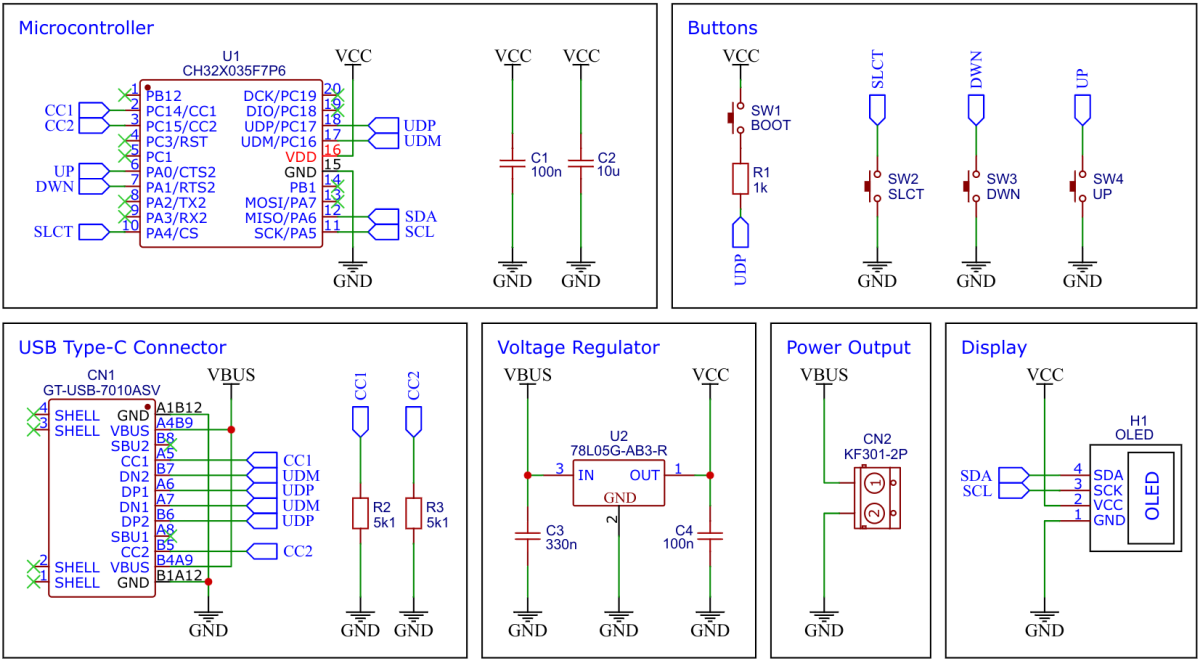
## CH32X035 F7P6 32-bit RISC-V USB Microcontroller
CH32X035F7P6 is a low-cost microcontroller that utilizes the QingKe 32-bit RISC-V4C core, supporting the RV32IMAC instruction set along with self-extending instructions. This microcontroller comes with a built-in USB PHY, supporting USB2.0 full-speed device functions and a USB PD PHY with source and sink capabilities. It features a programmable protocol I/O controller (PIOC), an operational amplifier (OPA) with programmable gain (PGA), an analog comparator (CMP), a 12-bit analog-to-digital converter (ADC), an 11-channel touch-key controller, 3 groups of USART, I2C, SPI, multiple timers, and various other peripheral resources. The device can operate at clock frequencies of up to 48MHz and is compatible with a supply voltage range of 2.0V to 5.5V. The CH32X035F7P6 includes 48KB of flash, 20KB of SRAM, and an embedded USB bootloader.
## 78L05 Voltage Regulator
The 78L05 is a simple and inexpensive voltage regulator that can convert input voltages up to 30V to an output voltage of 5V with an output current of up to 100mA and a dropout voltage of 1.7V. The 78L05 supplies all elements of the circuit with up to 5V.
## SSD1306 OLED Display Module
A low-cost SSD1306 4-pin I2C 128x64 pixels 0.96-inch OLED module is used as the display device. Make sure to acquire one with the correct pinout!
# Software
## USB Bootloader
### Installing Drivers for the Bootloader
On Linux you do not need to install a driver. However, by default Linux will not expose enough permission to upload your code with the USB bootloader. In order to fix this, open a terminal and run the following commands:
```
echo 'SUBSYSTEM=="usb", ATTR{idVendor}=="4348", ATTR{idProduct}=="55e0", MODE="666"' | sudo tee /etc/udev/rules.d/99-ch55x.rules
echo 'SUBSYSTEM=="usb", ATTR{idVendor}=="1a86", ATTR{idProduct}=="55e0", MODE="666"' | sudo tee -a /etc/udev/rules.d/99-ch55x.rules
sudo udevadm
```
For Windows you can use the [Zadig](https://zadig.akeo.ie/) tool to install the correct driver. Here, click "Options" -> "List All Devices" and select the USB module. Then install the libusb-win32 driver. To do this, the board must be connected and the microcontroller must be in bootloader mode.
### Entering Bootloader Mode
The bootloader must be started manually for new uploads. To do this, the board must first be disconnected from the USB port. Now press the BOOT button and keep it pressed while reconnecting the board to the USB port of your PC. The chip now starts in bootloader mode, the BOOT button can be released and new firmware can be uploaded via USB within the next couple of seconds.
## Compiling and Uploading Firmware using the Makefile
### Linux
Install the toolchain (GCC compiler, Python3, and chprog):
```
sudo apt install build-essential libnewlib-dev gcc-riscv64-unknown-elf
sudo apt install python3 python3-pip
pip install chprog
```
Open a terminal and navigate to the folder with the *makefile*. Press the BOOT button and keep it pressed while connecting the board to the USB port of your PC. Run the following command to compile and upload:
```
make flash
```
### Other Operating Systems
Follow the instructions on [CNLohr's ch32v003fun page](https://github.com/cnlohr/ch32v003fun/wiki/Installation) to set up the toolchain on your respective operating system (for Windows, use WSL). Also, install [Python3](https://www.pythontutorial.net/getting-started/install-python/) and [chprog](https://pypi.org/project/chprog/). Compile and upload with "make flash". Note that I only have Debian-based Linux and have not tested it on other operating systems.
## Compiling and Uploading Firmware using PlatformIO
- Install [PlatformIO](https://platformio.org) and [platform-ch32v](https://github.com/Community-PIO-CH32V/platform-ch32v). Follow [these instructions](https://pio-ch32v.readthedocs.io/en/latest/installation.html) to do so. Linux/Mac users may also need to install [pyenv](https://realpython.com/intro-to-pyenv).
- Click on "Open Project" and select the firmware folder with the *platformio.ini* file.
- Press the BOOT button and keep it pressed while connecting the board to the USB port of your PC. Then click "Upload".
## Uploading pre-compiled Firmware Binary
WCH offers the free but closed-source software [WCHISPTool](https://www.wch.cn/downloads/WCHISPTool_Setup_exe.html) to upload firmware with Windows via the USB bootloader. Press the BOOT button and keep it pressed while connecting the board to the USB port of your PC. Release the BOOT button, open the *pd_tester.hex* file in the *bin* folder with WCHISPTool and upload it to the microcontroller.
If [Python3](https://www.pythontutorial.net/getting-started/install-python/) is installed, you can also use the platform-independent open-source command-line tool [chprog](https://pypi.org/project/chprog/) for uploading:
```
chprog bin/pd_tester.bin
```
# Building Instructions
1. Take the Gerber files (the *zip* file inside the *hardware* folder) and upload them to a PCB (printed circuit board) manufacturer of your choice (e.g., [JLCPCB](https://jlcpcb.com/)). They will use these files to create the circuit board for your device and send it to you.
2. Once you have the PCB, you can start soldering the components onto it. Use the BOM (bill of materials) and schematic as a guide to make sure everything is connected correctly. You can find the corresponding files in the *hardware* folder. Remove the plastic part from the pin header of the OLED, trim the pins, and solder the OLED module flush onto the PCB. Do not solder the screw terminal yet.
3. Print the casing with your 3D printer. You can find the corresponding *stl* files in the *3dprint* folder.
4. Insert the button extensions into the corresponding holes on the top part of the casing. Insert the circuit board and secure it with 4 self-tightening M2x5mm screws.
5. Now solder the screw terminal onto the circuit board.
6. Close the casing with the back panel.
7. Upload the firmware by following the instructions in the previous section (see above).
# Operating Instructions
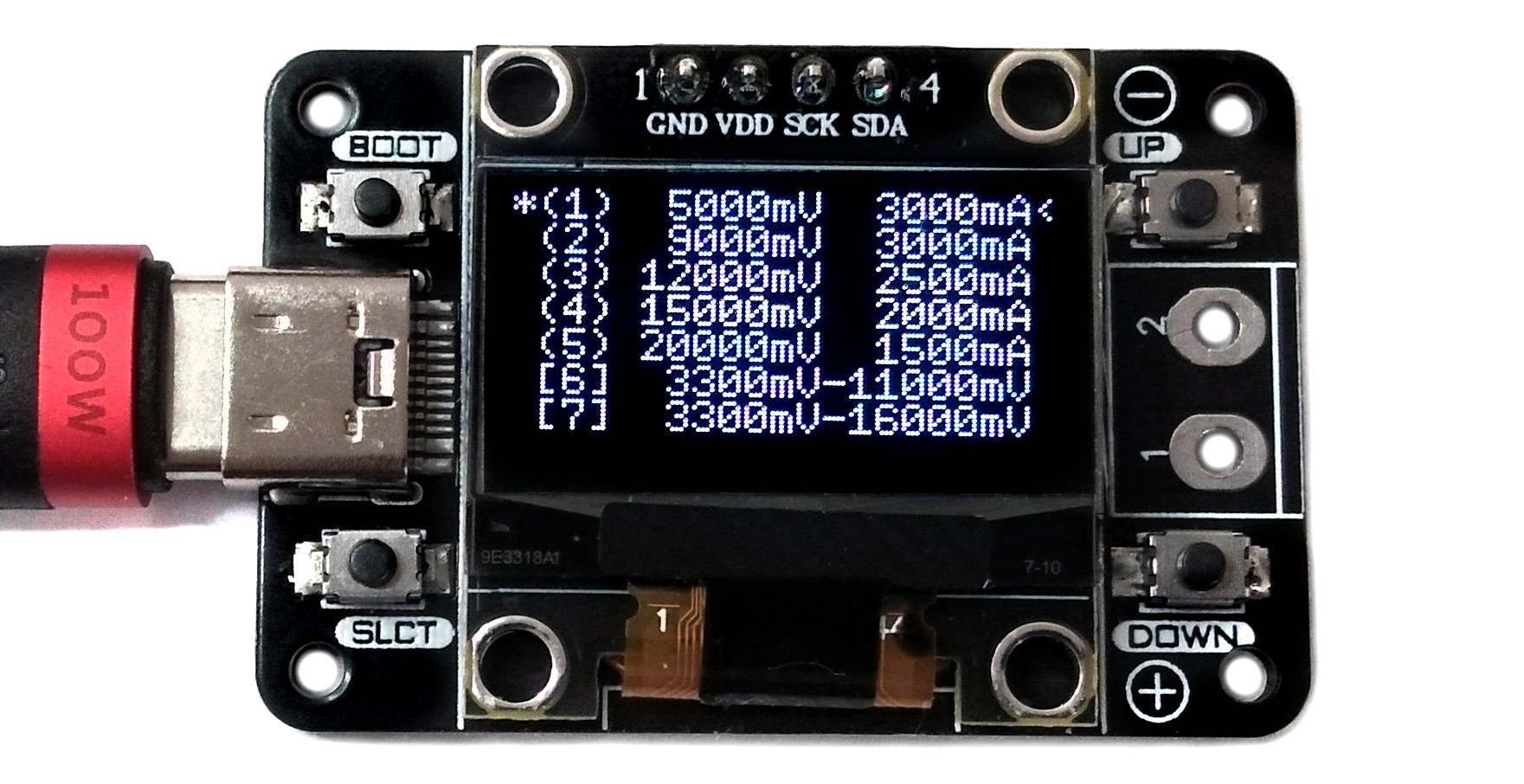
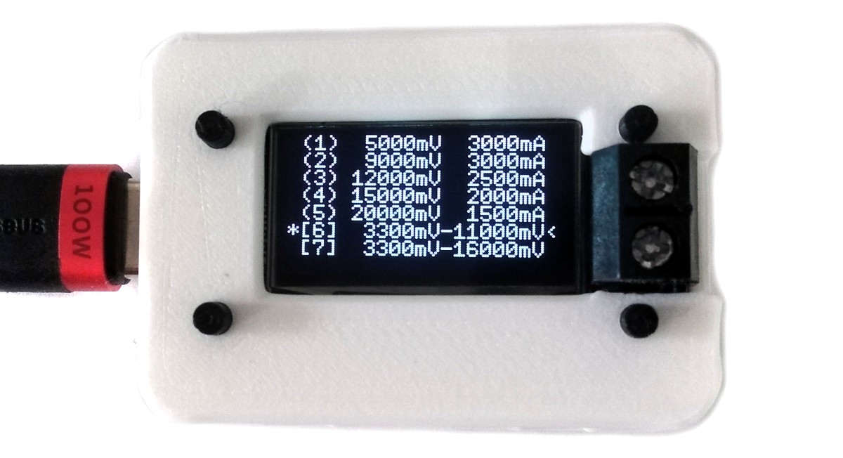
1. Connect the USB PD Tester to a USB Type-C PD power supply using a USB-C cable. The available PDOs and their corresponding capabilities are displayed on the OLED.
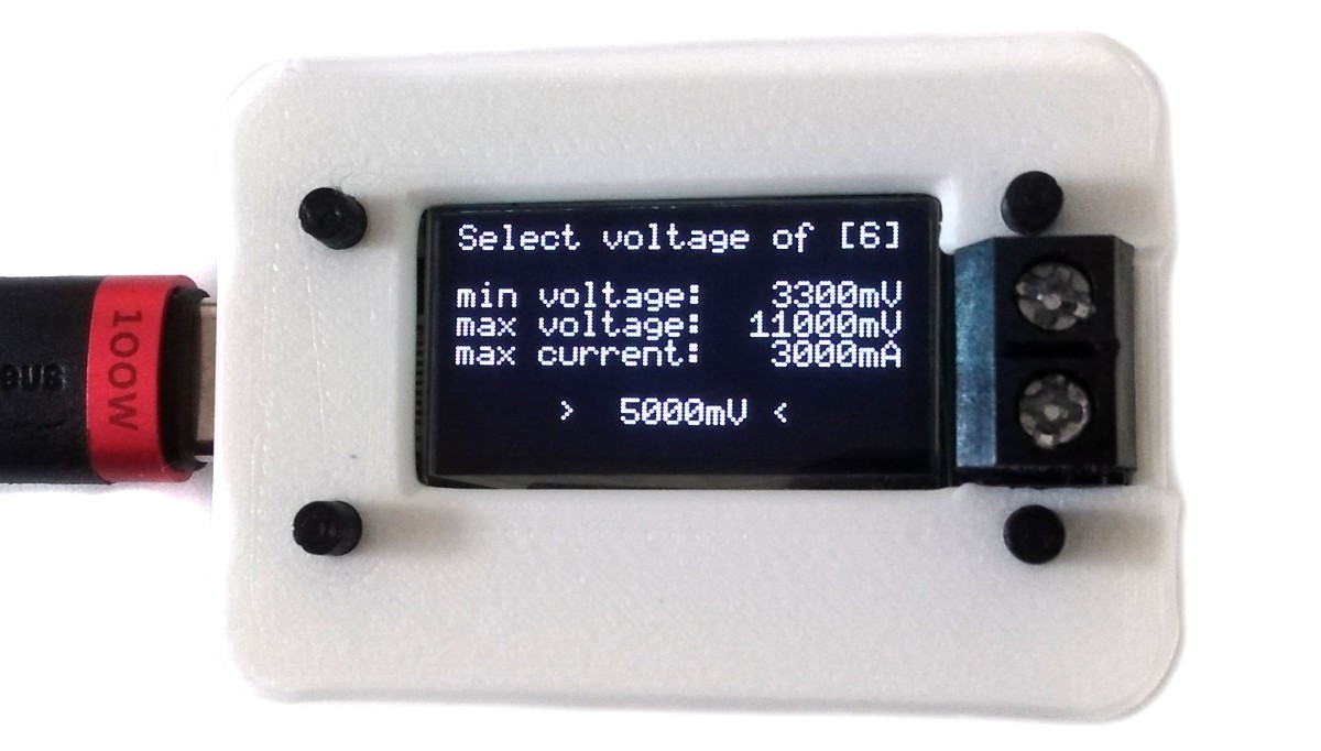
2. Utilize the UP and DOWN buttons to choose the desired PDO. A left-angle bracket on the right side serves as the selection indicator. Programmable PDOs, indicated by numbers within square brackets, allow precise adjustments of the output voltage in 20mV steps within the specified range.
3. Press the SLCT button to activate the chosen PDO. An asterisk on the left side of the PDO confirms the activation.
4. The selected voltage is now accessible on the screw terminal for further use.
# References, Links and Notes
- [EasyEDA Design Files](https://oshwlab.com/wagiminator)
- [MCU Templates](https://github.com/wagiminator/MCU-Templates)
- [MCU Flash Tools](https://github.com/wagiminator/MCU-Flash-Tools)
- [CH32X035 Datasheets](http://www.wch-ic.com/products/CH32X035.html)
- [SSD1306 Datasheet](https://cdn-shop.adafruit.com/datasheets/SSD1306.pdf)
- [78L05 Datasheet](https://datasheet.lcsc.com/lcsc/2209271730_HX-hengjiaxing-78L05_C5181466.pdf)
- [ATtiny814 USB PD Adapter](https://github.com/wagiminator/ATtiny814-USB-PD-Adapter)
- [ATtiny412 USB PD Inverter](https://github.com/wagiminator/ATtiny412-USB-PD-Inverter)
- [TI Primer on USB PD](https://www.ti.com/lit/wp/slyy109b/slyy109b.pdf)
- [CH32X035 F7P6 on Aliexpress](https://aliexpress.com/item/1005006199310724.html)
- [128x64 OLED on Aliexpress](https://aliexpress.com/wholesale?SearchText=128+64+0.96+oled)
# License

This work is licensed under Creative Commons Attribution-ShareAlike 3.0 Unported License.
(http://creativecommons.org/licenses/by-sa/3.0/)
================================================
FILE: software/pd_tester/bin/pd_tester.hex
================================================
:040000006F108024D9
:10000400000000000000000036020000360200007C
:1000140000000000360200000000000000000000A4
:10002400360200003602000000000000000000005C
:10003400360200000000000036020000000000004C
:100044003602000036020000360200000000000004
:1000540036020000360200003602000036020000BC
:1000640036020000360200003602000036020000AC
:10007400360200003602000036020000360200009C
:10008400360200003602000036020000360200008C
:10009400360200003602000036020000360200007C
:1000A400360200003602000036020000360200006C
:1000B400360200003602000036020000360200005C
:1000C400360200001E08000036020000360200005E
:0C00D40036020000360200003602000078
:1000E000B7F700E09C4737F700E03E951C47898F43
:1000F000E3CE07FE828079714ECE5EC6B70910FF4F
:10010000B70B00F122D426D252CC56CA5AC862C4C8
:1001100066C206D64AD0AA84A14A37140140FD1B04
:10012000370C0003B70C0004FD19370B4000370AE9
:1001300030000327048093978401E18733777701A8
:1001400063DA0708336797012320E48003270480DC
:100150000945FD1A33773701336767012320E480AF
:10016000413703270480860493FAFA0F3377370167
:10017000336747012320E48093F4F40FE39B0AFAEA
:1001800003270480B70700F1FD177D8FB707000430
:100190005D8F2320E480832704800945B3F737016E
:1001A000B3E767012320F480253F83270480B25002
:1001B0009254B3F93701B3E9490123203481225421
:1001C0000259F249624AD24A424BB24B224C924CFB
:1001D000456182803367870185BF411122C437148E
:1001E000014003270480B70700F126C29384F7FF7C
:1001F000658FB707000306C65D8F2320E48009459D
:10020000C53503270480B70710FFFD177D8FB7079B
:1002100040005D8F2320E4800945D9358327048081
:1002200037070004B240E58FD98F2320F4802244A1
:1002300092444101828001A09387C18603C7470190
:1002400083C65701158F1377F70F6368A700DC4744
:100250000A053E950355E5FF8280198D1947330540
:10026000E5029C4B3E950355A5FF82809387C1868E
:1002700003C7470183C65701158F1377F70F6368CC
:10028000A700DC470A053E950355E5FF8280198DDE
:1002900019473305E5029C4B3E950355C5FF828007
:1002A0009387C18603C7470183C65701158F13770C
:1002B000F70F6368A700DC470A053E950355C5FFA5
:1002C0008280198D19473305E5029C4B3E950355F5
:1002D000E5FF8280B77702401307200A2396E700E4
:1002E0002397E7009387C186A3840700238507002F
:1002F00023840700238A0700A38A070023A007009E
:1003000023A207001387418323810702D8C7A38153
:1003100007021387C1802382070298CB0547238BEE
:10032000E70023800702238DE700A38DE700056720
:1003300013078738239EE700239FE7008280B77763
:10034000024003D70700118B21C303D7E700420700
:100350004183136707012397E700B777024013072C
:10036000F0042391E7004205A38207004181239313
:10037000A700A384070003C747001377F70F13678D
:1003800037002382E700828003D7C70042074183FA
:10039000136707012396E700C9B7797122D426D2E3
:1003A0004AD04ECE52CC56CA9387C18606D65AC87A
:1003B0005EC6239F07000569238007029304F00FA0
:1003C0001384C1861309892D93894183138A8181FE
:1003D000834B040293FBFB0F63960B00FD1493F415
:1003E000F40F91ECB25022540259F249624AD24AB7
:1003F000424BB24B3335900092544561828037B501
:10040000030013050598E939B777024003D7C70001
:10041000420741831377E7F1420741832396E700C0
:1004200003D7C70042074183136707042396E700F9
:1004300083D6C70003D7E700C2064207418313777C
:10044000E7F1420741832397E70003D7E700C18222
:1004500042074183136707042397E70083D7E70028
:100460000947858B99E313F7160083578401854666
:100470008507C207C183231CF4001C406393D70483
:100480006318F70823050400834794009546850701
:1004900093F7F70FA304F4008347940093F7F70F43
:1004A00063F1F602A304040089471CC0B77602403A
:1004B00083D70600C207C183ED9BC207C183239087
:1004C000F6001440854763FBD70249E78347840061
:1004D0001547850793F7F70F2304F400834784003B
:1004E00093F7F70F637CF700230404002320040034
:1004F000B7E700E03707020023A2E718032B040048
:100500001C402547636FF7088A07CA979C43828778
:100510008947A3040400631CF7028347A40095469F
:10052000850793F7F70F2305F4008347A40093F79B
:10053000F70FE3F8F6F82305040018C0B776024079
:1005400083D70600C207C18393E747008DBF230509
:10055000040085BF2304040055B7B7E700E0370760
:10056000020023A2E718BD3385471CC01DA85840D0
:100570001C406308F7023777024093077007231186
:10058000F7008347470093F7C70F93E7270023023D
:10059000F700B7E700E0A38807423707020023A26D
:1005A000E710232264012DB58347340293F7F70F38
:1005B000EDDBA3010402B7E700E0370702000328E0
:1005C000C400144823A2E718A30A0400B70800F0E7
:1005D000370300C0294E9305200319461305400632
:1005E0008347440193F7F70F63EAFB00B7E700E0A6
:1005F0003707020023A2E710914785BF13972B000E
:10060000B307EA009C43B3FE170163986E060347E5
:10061000540193DE170193FEFE0F1377F70F330794
:10062000C702B38EAE0236972311D7010347540198
:1006300093DE870093FEFE0F1377F70F3307C70291
:1006400093F7F707B38EAE0236972310D70103470F
:100650005401B387B7021377F70F3307C7023697F2
:100660002312F70083475401850793F7F70FA30A76
:10067000F400850B93FBFB0FA5B793FEF73FA9830F
:1006800093F7F73FB38ECE034297B387B702231099
:10069000D7012311F700F1BF58401C406300F70C4D
:1006A0008347A401834624020565130725009D8A1C
:1006B000A606D98E21671307F7E1F98E0347640177
:1006C00093F6F6F313F6F70F0D8B1A07D98E03473F
:1006D0004401034854019395C7011377F70F13782A
:1006E000F80F330707416355C7088357C4015147C3
:1006F000C207C183B3D7E7021307F5FFF98FA60737
:1007000003475401CD8F834544011377F70F329788
:1007100093F5F50F0D8F19467D173307C702138622
:10072000C180329703574700130620033357C7028F
:10073000370600031377F707518F370600FD1306BE
:1007400006F8F18FD98F138781842311F700C183B5
:100750002310D7002312F7001945D53683474402EA
:1007600093F7F70FE38F07E2230204029547F5BBE7
:100770001307F6FF0A074E9703570700A9473706E6
:1007800000033357F7021377F73F9317A700518FF2
:100790005D8FB367B70045BF8347340293F7F70F08
:1007A000E38107E0A3010402A5471CC0231C040049
:1007B000CDBB85472300F4020347A4018347B4015E
:1007C0001377F70F93F7F70F631CF7000357C40174
:1007D0008357E4014207C2074183C183E303F7DC87
:1007E0008347A401094593F7F70FA30DF40083573E
:1007F000C401C207C183231FF400230004028347FE
:100800002402034764019D8BA6070D8B1A0793E70B
:100810007700D98F2394F1841D36A947B9B35D7150
:100820003ED0B77702403AD203C7970086C696C437
:100830009AC29EC022DE26DC2ADA2ED832D636D4E0
:1008400042CE46CC4ACA72C876C67AC47EC21377F4
:10085000070235CB03C7970085460D8B631BD70472
:1008600083D7A7009546C207C18363F4F60403D477
:1008700081841389818493160401C1869384C1867F
:1008800063CE060E1D66618E9376F4016310061228
:100890008D476383F60E99476388F6106390E60EE2
:1008A0002382D40283C72402850793F7F70F23819D
:1008B000F402377702408347970093F7F70F93E7E7
:1008C0000702A304F700B777024003C79700620747
:1008D0006187635D070403D7C700854642074183EC
:1008E0003D9B420741832396E70003D7E700420779
:1008F00041833D9B420741832397E700130770071D
:100900002391E70003C747001377C70F136727003A
:100910002382E7001387C186A301D70203C797008C
:10092000136707F81377F70FA384E70037770240C0
:100930008347970093F7070491CB8347970093F77A
:10094000F70F93E70704A304F70069327254B64027
:10095000A64216438643E2545255C2553256A25619
:10096000125782577248E2485249424EB24E224FC5
:10097000924F6161730020309D479CC01305005A5F
:10098000EFF00FF6A381040203C7640193579400AC
:100990009D8BA6070D8B1A0793E71700D98F094582
:1009A0002310F900693A31B7A147C1BFE398E6FCCB
:1009B0000D4798C01357C4001D8B238AE4001357BA
:1009C00064000D8B238BE40093878184014771467B
:1009D000938681818507E303C7FA03C51700B385B2
:1009E000E60005072380A500F5B7411122C437149E
:1009F000014083270480370700F17D17F98F3707FF
:100A0000000306C6D98F2320F4800945EFF04FED8F
:100A100083270480370710FF7D17F98F37073000D1
:100A2000D98F2320F4802244B2401305800741016E
:100A30006FF06FEC411122C426C206C69D47AA84FE
:100A4000014463E3B7002E8423849180A3848180D2
:100A5000693F0145EFF02FEA130404FB1375F40F0F
:100A6000EFF06FE913F5F400EFF0EFE813D5440071
:100A700013650501EFF02FE82244B2409244410192
:100A80006FF0AFF5411122C44AC006C626C2214408
:100A90001309F00F7D141374F40F63182401B2408E
:100AA00022449244024941018280A285014559377E
:100AB0002D3F13050004EFF00FE493040008FD142C
:100AC000014593F4F40FEFF00FE3F5F8EFF0EFF0DA
:100AD000A285014585377DBF011501114205418180
:100AE0004EC603C7818022CC131425002A944204E9
:100AF00006CE26CA4AC89307A00741809389818001
:100B000063F9E70083C591800145850593F5F50FED
:100B10001537E13D13050004EFF0EFDD93045400B9
:100B20000145C2040569EFF00FDDC1801309093AE0
:100B3000A287CA97050403C5070042044180EFF06D
:100B40008FDBE39784FEEFF04FE983C70900F240A3
:100B5000624499072380F900D2444249B2490561B1
:100B60008280AA8793F707061375F50791C3ADB77F
:100B7000A9476319F50083C59180850593F5F50FA5
:100B800001454DBDB5476315F50083C59180CDBFC7
:100B90008280014863DC0500B305B040E205E185D1
:100BA000635605003305A0401308D00293080002E5
:100BB000635806003306C04062066186930800034E
:100BC000D1478146254E63D3C70A8280BE86B3775C
:100BD000B50213F7F70F6370FE0813077703335559
:100BE000B50200101377F70F3303D4009387160074
:100BF0002306E3FE93F7F70F71F9630C0800130760
:100C000000036388E800A2978906238607FF93F70D
:100C1000F60F3E8763C4C704630D08009306000304
:100C20006399D80014108507369793F7F70F2306BA
:100C300007FF1384F7FF64001374F40F2694034531
:100C400004000537A2877D14E39BF4FEB2502254C2
:100C50009254456182801307070351B7141085072A
:100C6000369793F7F70F230617FF65B7797106D606
:100C700022D426D2A9BF411122C4370400208345C3
:100C8000140026C2AA84FD1593F5F50F13058007FD
:100C900006C64D331305000281351387C18683468E
:100CA00047019307140093F6F60F63F49602054785
:100CB0002380E70083C5070013058007FD1593F522
:100CC000F50F8D3B2244B24092441305C00341010D
:100CD00021B581E403474701E1BF23809700D9BFD5
:100CE000411126C2B70400209384040083C5040088
:100CF00022C42A84FD1593F5F50F014506C61D3B58
:100D000013050002D13B9305F4FF014593F5F50F60
:100D10002380840005332244B24092441305A0028C
:100D200041015DBB1D7126DAA40022DC4ED652D4EF
:100D300056D25AD05ECE62CC06DE4AD82E84B2C4D9
:100D4000B6C6BAC8BECAC2CCC6CE26C69309500221
:100D5000130A0003A54A294B930B3007130C3006E6
:100D60000345040009EDF2506254D2544259B2597D
:100D7000225A925A025BF24B624C256182806306D2
:100D800035010504F93B2689A1A883471400638C2B
:100D9000370109040147639647018347040005476B
:100DA0000504014639A8130550023D33834724004A
:100DB0000D04CDB7B30766030504B6973E96834787
:100DC000F4FF938607FDE3F7DAFE19C33306C0404C
:100DD000639D770113894400844003C5040019E131
:100DE000CA84BDBF8504B53BCDBF6398870103C5E9
:100DF000040013894400B533E5B7B5D7130750078E
:100E00006389E70213074006638DE7001307800735
:100E10006387E702130720068945638DE7007D1489
:100E20009DB76206138944006186D9558840953381
:100E300045BFA9456206138944006186C5BFC14507
:100E4000D5BF4111B70700204AC003C9170026C209
:100E5000AA844A8522C406C6EFF00FBE13842180FF
:100E6000636895024A85EFF02FBD2310A4009945D1
:100E70007945C936035604002244B24092440249DF
:100E80008565056593850530130525B6410159BD76
:100E90004A85EFF0AFBD63E6A4004A85EFF00FBDD1
:100EA000E9B723109400E1B7797126D256CAB70486
:100EB000004022D44AD04ECE52CC06D60544D93674
:100EC000938AC18605698569FD14056A83C74A014D
:100ED00093F7F70F63F48702B707002003C51700E5
:100EE000593BB70700202254B25092540259F2499C
:100EF000624AD24A03C507004561DDB383C74A0190
:100F000003C75A01998F93F7F70F63EA870203A784
:100F1000CA00B30794008A07BA9783D627002285B0
:100F200036C6EFF0EFB7B2462A8722869305CA305D
:100F3000130529B60504FD331374F40F41BF228550
:100F4000EFF08FAF2AC62285EFF04FB2B2462A8764
:100F5000228693850932E9BFB717014003A70780AE
:100F6000B70610FFFD167971758FB706400006D6DB
:100F700022D426D24AD04ECE52CC56CA5AC85EC6C9
:100F800062C466C26AC0558F23A0E78003A70780AA
:100F9000B70600F1FD16758FB7060004558F13864E
:100FA000078023A0E780930700025CCA37A52400CE
:100FB000930700045CCA130505F0EFF06F92353417
:100FC000014505690144EFF00F9381441309095865
:100FD000AD49B307990003C507008504EFF0AF9151
:100FE000E39934FFEFF06F9F713C05698565938548
:100FF0004533130529B63D33B7170240984FB7065E
:101000000200B71401401367170198CFD84BCA8A62
:10101000558FD8CB83A744C0B7060044370701409B
:10102000A207A183D58F23A2F4C01C4F93E70730FA
:101030001CCF93878184C20737770240C18323186E
:10104000F700F977A1072310F700F157A304F70081
:10105000EFF0AFB401E9856593854534130529B6F2
:10106000D13101A0913583A70480B706F1FFFD16A9
:10107000C19B93E7870023A0F480854723A8F480D1
:1010800083A70480B70B002093F7F7F093E70708D6
:1010900023A0F480894723A8F48083A70480938940
:1010A000C186856CF58FB7060800D58F23A0F48024
:1010B000C14723A8F480056DB714014083A784803D
:1010C000858B85CF83A78480898B99EB03C51B0013
:1010D00005051375F50F453683A78480898BEDDFF1
:1010E00083A78480C18B8DC7EFF02FAB37550700E6
:1010F00013050530EFE0DFFED1B703C51B007D15FA
:101100001375F50F8D3E83A78480858BEDDF5DBF62
:1011100083C7490103C7590103C91B00998F93F77E
:10112000F70F63E7270303A7C90093172900238D4F
:101130002901BA9783D7E7FF239EF900EFF0EFA5C7
:1011400019C14A85713E83A78480C18BEDDF69BFD9
:10115000EFF05F934A869385CC3413852AB6D9364F
:101160004A85EFF06F8D2A8693054D3613852AB692
:10117000553E4A85EFF08F8F85652A8693858537A2
:1011800013852AB645364A85EFF08F9185652A8604
:101190009385C53813852AB6713603D52180138B04
:1011A0002180453183A78480C18BEDDF375A07004A
:1011B00013050A30EFE0DFF2130CF00F130A0A30C8
:1011C00083A784801387048003550B00C18B91EFA4
:1011D000238D2901239EA900EFF02F9C09C5B70795
:1011E000002023802701C931B9BF1C47858B95E7B3
:1011F000510542054181B1317D141374F40F63161A
:1012000084010944EFF06F9965BF83A78480858BC3
:10121000EDFB5285EFE0DFECC5B71C47898B95E30A
:1012200031154205418131397D141374F40FE30AFD
:1012300084FD83A78480898BE9F75285EFE05FEA1C
:10124000E5B7130420037DBF8567938787F597F182
:10125000FF1F9381215B174100201301A1DA7D4517
:10126000731005BC13058008732005308D457390FD
:101270004580130540004D8D731055307390173421
:10128000B70700200567938707001307C7589386A1
:10129000818063E8D702938781801387418963E85F
:1012A000E702B7270240094798C3B717024023A2B5
:1012B000070037F700E0954614C3714798CF7300D5
:1012C000203010431107910723AEC7FED9B791070D
:1012D00023AE07FEE9B700005A050000A205000092
:1012E0006E050000A805000098060000A205000099
:1012F000A2050000A205000098070000B207000048
:101300003E2536646D56203C0000000020282564F0
:10131000292536646D56202535646D412000000076
:10132000205B25645D2536646D562D2535646D562C
:1013300020000000436F6E6E656374696E672E2E29
:101340002E0000004641494C4544000053656C6541
:10135000637420766F6C74616765206F66205B250F
:10136000645D0A006D696E20766F6C746167653A22
:101370002537646D560000006D617820766F6C74BF
:101380006167653A2537646D560000006D6178200D
:1013900063757272656E743A2537646D41000000A2
:1013A000000000000000005F0000000700070014BC
:1013B0007F147F14242A7F2A12231308646236497B
:1013C0005522500004030000001C2241000041226D
:1013D0001C0014083E081408083E0808008060003D
:1013E00000080808080800606000002010080402D7
:1013F0003E5149453E44427F404042615149462268
:10140000414949361814127F102F494949313E4944
:101410004949320301710907364949493626494984
:10142000493E0036360000008068000000081422A3
:1014300000141414141400221408000201510906A7
:101440003E415D555E7C1211127C7F494949363E12
:10145000414141227F4141221C7F494949417F0945
:101460000909013E4149493A7F0808087F41417F07
:1014700041412040413F017F081422417F404040CC
:10148000407F020C027F7F0408107F3E4141413EB5
:101490007F090909063E4141C1BE7F091929462637
:1014A0004949493201017F01013F4040403F1F202F
:1014B00040201F3F4038403F631408146307087002
:1014C00008076151494543007F414100020408106B
:1014D000200041417F000804020408404040404091
:1014E000000609090620545454787F44444438388F
:1014F00044444428384444447F385454541808FE23
:1015000009010218A4A4A4787F0404047800447D8F
:1015100040000080847D00417F10284400417F40CE
:10152000007C047C04787C04040478384444443807
:10153000FC2424241818242424FC7C08040408080F
:1015400054545420043F4440203C4040403C1C2024
:1015500040201C3C4030403C44281028441CA0A0A3
:10156000A07C4464544C4408083641410000FF000C
:101570000041413608080804081008FFFFFFFFFF7C
:0C158000A83F8D142000DA12A1C8AF00B3
:08158C000101881300000000BA
:00000001FF
================================================
FILE: software/pd_tester/config.h
================================================
// ===================================================================================
// User Configurations
// ===================================================================================
#pragma once
// Pin definitions
#define PIN_KEY_UP PA0 // pin connected to UP button (active low)
#define PIN_KEY_DOWN PA1 // pin connected to DOWN button (active low)
#define PIN_KEY_SLCT PA4 // pin connected to SELECT button (active low)
#define PIN_SCL PA5 // I2C SCL connected to OLED
#define PIN_SDA PA6 // I2C SDA connected to OLED
#define PIN_LED PB1 // pin connected to LED (active low)
// If using PC18 and/or PC19 for OLED, disable SWJ
#define DISABLE_SWJ 0 // 0: normal SWJ pins, 1: OLED pins
// MCU supply voltage
#define USB_VDD 0 // 0: 3.3V, 1: 5V
================================================
FILE: software/pd_tester/ld/ch32x035.ld
================================================
ENTRY( jump_reset )
MEMORY
{
FLASH (rx) : ORIGIN = 0x00000000, LENGTH = 62K
RAM (xrw) : ORIGIN = 0x20000000, LENGTH = 20K
}
SECTIONS
{
.init :
{
_sinit = .;
. = ALIGN(4);
KEEP(*(SORT_NONE(.init.jump)))
KEEP(*(SORT_NONE(.init.data)))
. = ALIGN(4);
_einit = .;
} >FLASH AT>FLASH
.vector :
{
. = ALIGN(4);
*(.vector);
. = ALIGN(4);
} >FLASH AT>FLASH
.text :
{
. = ALIGN(4);
*(.text)
*(.text.*)
*(.rodata)
*(.rodata*)
*(.glue_7)
*(.glue_7t)
*(.gnu.linkonce.t.*)
. = ALIGN(4);
} >FLASH AT>FLASH
.fini :
{
KEEP(*(SORT_NONE(.fini)))
. = ALIGN(4);
} >FLASH AT>FLASH
PROVIDE(_etext = .);
PROVIDE(_eitcm = .);
.preinit_array :
{
PROVIDE_HIDDEN(__preinit_array_start = .);
KEEP(*(.preinit_array))
PROVIDE_HIDDEN(__preinit_array_end = .);
} >FLASH AT>FLASH
.init_array :
{
PROVIDE_HIDDEN(__init_array_start = .);
KEEP(*(SORT_BY_INIT_PRIORITY(.init_array.*)SORT_BY_INIT_PRIORITY(.ctors.*)))
KEEP(*(.init_array EXCLUDE_FILE(*crtbegin.o *crtbegin?.o *crtend.o *crtend?.o) .ctors))
PROVIDE_HIDDEN(__init_array_end = .);
} >FLASH AT>FLASH
.fini_array :
{
PROVIDE_HIDDEN(__fini_array_start = .);
KEEP(*(SORT_BY_INIT_PRIORITY(.fini_array.*) SORT_BY_INIT_PRIORITY(.dtors.*)))
KEEP(*(.fini_array EXCLUDE_FILE(*crtbegin.o *crtbegin?.o *crtend.o *crtend?.o) .dtors))
PROVIDE_HIDDEN(__fini_array_end = .);
} >FLASH AT>FLASH
.ctors :
{
KEEP(*crtbegin.o(.ctors))
KEEP(*crtbegin?.o(.ctors))
KEEP(*(EXCLUDE_FILE(*crtend.o *crtend?.o) .ctors))
KEEP(*(SORT(.ctors.*)))
KEEP(*(.ctors))
} >FLASH AT>FLASH
.dtors :
{
KEEP(*crtbegin.o(.dtors))
KEEP(*crtbegin?.o(.dtors))
KEEP(*(EXCLUDE_FILE(*crtend.o *crtend?.o) .dtors))
KEEP(*(SORT(.dtors.*)))
KEEP(*(.dtors))
} >FLASH AT>FLASH
.dalign :
{
. = ALIGN(4);
PROVIDE(_data_vma = .);
} >RAM AT>FLASH
.dlalign :
{
. = ALIGN(4);
PROVIDE(_data_lma = .);
} >FLASH AT>FLASH
.data :
{
. = ALIGN(4);
*(.gnu.linkonce.r.*)
*(.data .data.*)
*(.gnu.linkonce.d.*)
. = ALIGN(8);
PROVIDE(__global_pointer$ = . + 0x800);
*(.sdata .sdata.*)
*(.sdata2*)
*(.gnu.linkonce.s.*)
. = ALIGN(8);
*(.srodata.cst16)
*(.srodata.cst8)
*(.srodata.cst4)
*(.srodata.cst2)
*(.srodata .srodata.*)
. = ALIGN(4);
PROVIDE(_edata = .);
} >RAM AT>FLASH
.bss :
{
. = ALIGN(4);
PROVIDE(_sbss = .);
*(.sbss*)
*(.gnu.linkonce.sb.*)
*(.bss*)
*(.gnu.linkonce.b.*)
*(COMMON*)
. = ALIGN(4);
PROVIDE(_ebss = .);
} >RAM AT>FLASH
PROVIDE(_end = _ebss);
PROVIDE(end = . );
PROVIDE(_eusrstack = ORIGIN(RAM) + LENGTH(RAM));
}
================================================
FILE: software/pd_tester/makefile
================================================
# ===================================================================================
# Project Makefile
# ===================================================================================
# Project: USB PD Tester for CH32X035
# Author: Stefan Wagner
# Year: 2024
# URL: https://github.com/wagiminator
# ===================================================================================
# Install toolchain:
# sudo apt install build-essential libnewlib-dev gcc-riscv64-unknown-elf
# sudo apt install python3 python3-pip
# pip install chprog
#
# Provide access permission to USB bootloader:
# echo 'SUBSYSTEM=="usb", ATTR{idVendor}=="4348", ATTR{idProduct}=="55e0", MODE="666"' | sudo tee /etc/udev/rules.d/99-ch55x.rules
# echo 'SUBSYSTEM=="usb", ATTR{idVendor}=="1a86", ATTR{idProduct}=="55e0", MODE="666"' | sudo tee -a /etc/udev/rules.d/99-ch55x.rules
# sudo udevadm control --reload-rules
#
# Set the device to bootloader mode and type "make flash" in the command line.
# ===================================================================================
# Files and Folders
TARGET = pd_tester
INCLUDE = include
SOURCE = src
BIN = bin
# Microcontroller Settings
F_CPU = 48000000
LDSCRIPT = ld/ch32x035.ld
CPUARCH = -march=rv32imac -mabi=ilp32
# Toolchain
PREFIX = riscv64-unknown-elf
CC = $(PREFIX)-gcc
OBJCOPY = $(PREFIX)-objcopy
OBJDUMP = $(PREFIX)-objdump
OBJSIZE = $(PREFIX)-size
NEWLIB = /usr/include/newlib
ISPTOOL = chprog $(BIN)/$(TARGET).bin
CLEAN = rm -f *.lst *.obj *.cof *.list *.map *.eep.hex *.o *.d
# Compiler Flags
CFLAGS = -g -Os -flto -ffunction-sections -fdata-sections -fno-builtin -nostdlib
CFLAGS += $(CPUARCH) -DF_CPU=$(F_CPU) -I$(NEWLIB) -I$(INCLUDE) -I$(SOURCE) -I. -Wall
LDFLAGS = -T$(LDSCRIPT) -lgcc -Wl,--gc-sections,--build-id=none
CFILES = $(wildcard ./*.c) $(wildcard $(SOURCE)/*.c) $(wildcard $(SOURCE)/*.S)
# Symbolic Targets
help:
@echo "Use the following commands:"
@echo "make all compile and build $(TARGET).elf/.bin/.hex/.asm"
@echo "make hex compile and build $(TARGET).hex"
@echo "make asm compile and disassemble to $(TARGET).asm"
@echo "make bin compile and build $(TARGET).bin"
@echo "make flash compile and upload to MCU"
@echo "make clean remove all build files"
$(BIN)/$(TARGET).elf: $(CFILES)
@echo "Building $(BIN)/$(TARGET).elf ..."
@mkdir -p $(BIN)
@$(CC) -o $@ $^ $(CFLAGS) $(LDFLAGS)
$(BIN)/$(TARGET).lst: $(BIN)/$(TARGET).elf
@echo "Building $(BIN)/$(TARGET).lst ..."
@$(OBJDUMP) -S $^ > $(BIN)/$(TARGET).lst
$(BIN)/$(TARGET).map: $(BIN)/$(TARGET).elf
@echo "Building $(BIN)/$(TARGET).map ..."
@$(OBJDUMP) -t $^ > $(BIN)/$(TARGET).map
$(BIN)/$(TARGET).bin: $(BIN)/$(TARGET).elf
@echo "Building $(BIN)/$(TARGET).bin ..."
@$(OBJCOPY) -O binary $< $(BIN)/$(TARGET).bin
$(BIN)/$(TARGET).hex: $(BIN)/$(TARGET).elf
@echo "Building $(BIN)/$(TARGET).hex ..."
@$(OBJCOPY) -O ihex $< $(BIN)/$(TARGET).hex
$(BIN)/$(TARGET).asm: $(BIN)/$(TARGET).elf
@echo "Disassembling to $(BIN)/$(TARGET).asm ..."
@$(OBJDUMP) -d $(BIN)/$(TARGET).elf > $(BIN)/$(TARGET).asm
all: $(BIN)/$(TARGET).lst $(BIN)/$(TARGET).map $(BIN)/$(TARGET).bin $(BIN)/$(TARGET).hex $(BIN)/$(TARGET).asm size
elf: $(BIN)/$(TARGET).elf removetemp size
bin: $(BIN)/$(TARGET).bin removetemp size removeelf
hex: $(BIN)/$(TARGET).hex removetemp size removeelf
asm: $(BIN)/$(TARGET).asm removetemp size removeelf
flash: $(BIN)/$(TARGET).bin size removeelf
@echo "Uploading to MCU ..."
@$(ISPTOOL)
clean:
@echo "Cleaning all up ..."
@$(CLEAN)
@rm -f $(BIN)/$(TARGET).elf $(BIN)/$(TARGET).lst $(BIN)/$(TARGET).map $(BIN)/$(TARGET).bin $(BIN)/$(TARGET).hex $(BIN)/$(TARGET).asm
size:
@echo "------------------"
@echo "FLASH: $(shell $(OBJSIZE) -d $(BIN)/$(TARGET).elf | awk '/[0-9]/ {print $$1 + $$2}') bytes"
@echo "SRAM: $(shell $(OBJSIZE) -d $(BIN)/$(TARGET).elf | awk '/[0-9]/ {print $$2 + $$3}') bytes"
@echo "------------------"
removetemp:
@echo "Removing temporary files ..."
@$(CLEAN)
removeelf:
@echo "Removing $(BIN)/$(TARGET).elf ..."
@rm -f $(BIN)/$(TARGET).elf
================================================
FILE: software/pd_tester/platformio.ini
================================================
; ===================================================================================
; PlatformIO Project Configuration File
; ===================================================================================
; Project: USB PD Tester for CH32X035
; Author: Stefan Wagner
; Year: 2024
; URL: https://github.com/wagiminator
; ===================================================================================
; Install PlatformIO and CH32V:
; https://pio-ch32v.readthedocs.io/en/latest/
; https://github.com/Community-PIO-CH32V/platform-ch32v
; ===================================================================================
[env:CH32X035]
platform = https://github.com/Community-PIO-CH32V/platform-ch32v.git
board = genericCH32X035F7P6
build_flags = -I. -D F_CPU=48000000
board_build.ldscript = $PROJECT_DIR/ld/ch32x035.ld
board_build.use_lto = yes
upload_protocol = minichlink
upload_command = pip install chprog && chprog $SOURCE
================================================
FILE: software/pd_tester/src/ch32x035.h
================================================
// ===================================================================================
// Header file for CH32X035/X034/X033 * v0.6 *
// ===================================================================================
// This contains a copy of ch32x035.h and core_riscv.h and other misc functions.
// NOTE: This file includes modifications by Stefan Wagner.
/********************************** (C) COPYRIGHT *******************************
* File Name : ch32x035.h
* Author : WCH
* Version : V1.0.0
* Date : 2023/04/06
* Description : CH32X035 Device Peripheral Access Layer Header File.
*********************************************************************************
* Copyright (c) 2021 Nanjing Qinheng Microelectronics Co., Ltd.
* Attention: This software (modified or not) and binary are used for
* microcontroller manufactured by Nanjing Qinheng Microelectronics.
*******************************************************************************/
#pragma once
/* MCU definitions */
#define __MPU_PRESENT 0 /* Other CH32 devices does not provide an MPU */
#define __Vendor_SysTickConfig 0 /* Set to 1 if different SysTick Config is used */
#ifdef __ASSEMBLER__
#define HSI_VALUE (48000000) /* Value of the internal oscillator in Hz */
#else
#define HSI_VALUE ((uint32_t)48000000) /* Value of the internal oscillator in Hz */
#ifdef __cplusplus
extern "C" {
#endif
#include <stdint.h>
/* Interrupt Number Definition, according to the selected device */
typedef enum IRQn
{
/****** RISC-V Processor Exceptions Numbers ***************************************/
NonMaskableInt_IRQn = 2, /* 2 Non Maskable Interrupt */
EXC_IRQn = 3, /* 3 Exception Interrupt */
Ecall_M_Mode_IRQn = 5, /* 5 Ecall M Mode Interrupt */
Ecall_U_Mode_IRQn = 8, /* 8 Ecall U Mode Interrupt */
Break_Point_IRQn = 9, /* 9 Break Point Interrupt */
SysTicK_IRQn = 12, /* 12 System timer Interrupt */
Software_IRQn = 14, /* 14 software Interrupt */
/****** RISC-V specific Interrupt Numbers *****************************************/
WWDG_IRQn = 16, /* Window WatchDog Interrupt */
PVD_IRQn = 17, /* PVD through EXTI Line detection Interrupt */
FLASH_IRQn = 18, /* FLASH global Interrupt */
EXTI7_0_IRQn = 20, /* External Line[7:0] Interrupts */
AWU_IRQn = 21, /* AWU global Interrupt */
DMA1_Channel1_IRQn = 22, /* DMA1 Channel 1 global Interrupt */
DMA1_Channel2_IRQn = 23, /* DMA1 Channel 2 global Interrupt */
DMA1_Channel3_IRQn = 24, /* DMA1 Channel 3 global Interrupt */
DMA1_Channel4_IRQn = 25, /* DMA1 Channel 4 global Interrupt */
DMA1_Channel5_IRQn = 26, /* DMA1 Channel 5 global Interrupt */
DMA1_Channel6_IRQn = 27, /* DMA1 Channel 6 global Interrupt */
DMA1_Channel7_IRQn = 28, /* DMA1 Channel 7 global Interrupt */
ADC1_IRQn = 29, /* ADC1 global Interrupt */
I2C1_EV_IRQn = 30, /* I2C1 Event Interrupt */
I2C1_ER_IRQn = 31, /* I2C1 Error Interrupt */
USART1_IRQn = 32, /* USART1 global Interrupt */
SPI1_IRQn = 33, /* SPI1 global Interrupt */
TIM1_BRK_IRQn = 34, /* TIM1 Break Interrupt */
TIM1_UP_IRQn = 35, /* TIM1 Update Interrupt */
TIM1_TRG_COM_IRQn = 36, /* TIM1 Trigger and Commutation Interrupt */
TIM1_CC_IRQn = 37, /* TIM1 Capture Compare Interrupt */
TIM2_UP_IRQn = 38, /* TIM2 Update Interrupt */
USART2_IRQn = 39, /* USART2 global Interrupt */
EXTI15_8_IRQn = 40, /* External Line[15:8] Interrupts */
EXTI25_16_IRQn = 41, /* External Line[25:16] Interrupts */
USART3_IRQn = 42, /* USART3 global Interrupt */
USART4_IRQn = 43, /* USART4 global Interrupt */
DMA1_Channel8_IRQn = 44, /* DMA1 Channel 8 global Interrupt */
USBFS_IRQn = 45, /* USBFS Host/Device global Interrupt */
USBFSWakeUp_IRQn = 46, /* USBFS Host/Device WakeUp Interrupt */
PIOC_IRQn = 47, /* PIOC global Interrupt */
OPA_IRQn = 48, /* OPA global Interrupt */
USBPD_IRQn = 49, /* USBPD global Interrupt */
USBPDWakeUp_IRQn = 50, /* USBPD WakeUp Interrupt */
TIM2_CC_IRQn = 51, /* TIM2 Capture Compare Interrupt */
TIM2_TRG_COM_IRQn = 52, /* TIM2 Trigger and Commutation Interrupt */
TIM2_BRK_IRQn = 53, /* TIM2 Break Interrupt */
TIM3_IRQn = 54, /* TIM3 global Interrupt */
} IRQn_Type;
#define HardFault_IRQn EXC_IRQn
/* IO definitions */
#ifdef __cplusplus
#define __I volatile /*!< defines 'read only' permissions */
#else
#define __I volatile const /*!< defines 'read only' permissions */
#endif
#define __O volatile /*!< defines 'write only' permissions */
#define __IO volatile /*!< defines 'read / write' permissions */
/* define compiler specific symbols */
#define __ASM __asm /*!< asm keyword for GNU Compiler */
#define __INLINE inline /*!< inline keyword for GNU Compiler */
#define RV_STATIC_INLINE static inline
typedef enum {NoREADY = 0, READY = !NoREADY} ErrorStatus;
typedef enum {DISABLE = 0, ENABLE = !DISABLE} FunctionalState;
typedef enum {RESET = 0, SET = !RESET} FlagStatus, ITStatus;
/* Analog to Digital Converter */
typedef struct
{
__IO uint32_t STATR;
__IO uint32_t CTLR1;
__IO uint32_t CTLR2;
__IO uint32_t SAMPTR1;
__IO uint32_t SAMPTR2;
__IO uint32_t IOFR1;
__IO uint32_t IOFR2;
__IO uint32_t IOFR3;
__IO uint32_t IOFR4;
__IO uint32_t WDHTR;
__IO uint32_t WDLTR;
__IO uint32_t RSQR1;
__IO uint32_t RSQR2;
__IO uint32_t RSQR3;
__IO uint32_t ISQR;
__IO uint32_t IDATAR1;
__IO uint32_t IDATAR2;
__IO uint32_t IDATAR3;
__IO uint32_t IDATAR4;
__IO uint32_t RDATAR;
__IO uint32_t CTLR3;
__IO uint32_t WDTR1;
__IO uint32_t WDTR2;
__IO uint32_t WDTR3;
} ADC_TypeDef;
/* DMA Channel Controller */
typedef struct
{
__IO uint32_t CFGR;
__IO uint32_t CNTR;
__IO uint32_t PADDR;
__IO uint32_t MADDR;
} DMA_Channel_TypeDef;
/* DMA Controller */
typedef struct
{
__IO uint32_t INTFR;
__IO uint32_t INTFCR;
} DMA_TypeDef;
/* External Interrupt/Event Controller */
typedef struct
{
__IO uint32_t INTENR;
__IO uint32_t EVENR;
__IO uint32_t RTENR;
__IO uint32_t FTENR;
__IO uint32_t SWIEVR;
__IO uint32_t INTFR;
} EXTI_TypeDef;
/* FLASH Registers */
typedef struct
{
__IO uint32_t ACTLR;
__IO uint32_t KEYR;
__IO uint32_t OBKEYR;
__IO uint32_t STATR;
__IO uint32_t CTLR;
__IO uint32_t ADDR;
uint32_t RESERVED;
__IO uint32_t OBR;
__IO uint32_t WPR;
__IO uint32_t MODEKEYR;
__IO uint32_t BOOT_MODEKEYR;
} FLASH_TypeDef;
/* Option Bytes Registers */
typedef struct
{
__IO uint16_t RDPR;
__IO uint16_t USER;
__IO uint16_t Data0;
__IO uint16_t Data1;
__IO uint16_t WRPR0;
__IO uint16_t WRPR1;
__IO uint16_t WRPR2;
__IO uint16_t WRPR3;
} OB_TypeDef;
/* General Purpose I/O */
typedef struct
{
__IO uint32_t CFGLR;
__IO uint32_t CFGHR;
__IO uint32_t INDR;
__IO uint32_t OUTDR;
__IO uint32_t BSHR;
__IO uint32_t BCR;
__IO uint32_t LCKR;
__IO uint32_t CFGXR;
__IO uint32_t BSXR;
} GPIO_TypeDef;
/* Alternate Function I/O */
typedef struct
{
uint32_t RESERVED0;
__IO uint32_t PCFR1;
__IO uint32_t EXTICR[2];
uint32_t RESERVED1;
uint32_t RESERVED2;
__IO uint32_t CTLR;
} AFIO_TypeDef;
/* Inter Integrated Circuit Interface */
typedef struct
{
__IO uint16_t CTLR1;
uint16_t RESERVED0;
__IO uint16_t CTLR2;
uint16_t RESERVED1;
__IO uint16_t OADDR1;
uint16_t RESERVED2;
__IO uint16_t OADDR2;
uint16_t RESERVED3;
__IO uint16_t DATAR;
uint16_t RESERVED4;
__IO uint16_t STAR1;
uint16_t RESERVED5;
__IO uint16_t STAR2;
uint16_t RESERVED6;
__IO uint16_t CKCFGR;
uint16_t RESERVED7;
} I2C_TypeDef;
/* Independent WatchDog */
typedef struct
{
__IO uint32_t CTLR;
__IO uint32_t PSCR;
__IO uint32_t RLDR;
__IO uint32_t STATR;
} IWDG_TypeDef;
/* Power Control */
typedef struct
{
__IO uint32_t CTLR;
__IO uint32_t CSR;
} PWR_TypeDef;
/* Reset and Clock Control */
typedef struct
{
__IO uint32_t CTLR;
__IO uint32_t CFGR0;
__IO uint32_t RESERVED0;
__IO uint32_t APB2PRSTR;
__IO uint32_t APB1PRSTR;
__IO uint32_t AHBPCENR;
__IO uint32_t APB2PCENR;
__IO uint32_t APB1PCENR;
__IO uint32_t RESERVED1;
__IO uint32_t RSTSCKR;
__IO uint32_t AHBRSTR;
} RCC_TypeDef;
/* Serial Peripheral Interface */
typedef struct
{
__IO uint16_t CTLR1;
uint16_t RESERVED0;
__IO uint16_t CTLR2;
uint16_t RESERVED1;
__IO uint16_t STATR;
uint16_t RESERVED2;
__IO uint16_t DATAR;
uint16_t RESERVED3;
__IO uint16_t CRCR;
uint16_t RESERVED4;
__IO uint16_t RCRCR;
uint16_t RESERVED5;
__IO uint16_t TCRCR;
uint16_t RESERVED6;
uint32_t RESERVED7;
uint32_t RESERVED8;
__IO uint16_t HSCR;
uint16_t RESERVED9;
} SPI_TypeDef;
/* TIM */
typedef struct
{
__IO uint16_t CTLR1;
uint16_t RESERVED0;
__IO uint16_t CTLR2;
uint16_t RESERVED1;
__IO uint16_t SMCFGR;
uint16_t RESERVED2;
__IO uint16_t DMAINTENR;
uint16_t RESERVED3;
__IO uint16_t INTFR;
uint16_t RESERVED4;
__IO uint16_t SWEVGR;
uint16_t RESERVED5;
__IO uint16_t CHCTLR1;
uint16_t RESERVED6;
__IO uint16_t CHCTLR2;
uint16_t RESERVED7;
__IO uint16_t CCER;
uint16_t RESERVED8;
__IO uint16_t CNT;
uint16_t RESERVED9;
__IO uint16_t PSC;
uint16_t RESERVED10;
__IO uint16_t ATRLR;
uint16_t RESERVED11;
__IO uint16_t RPTCR;
uint16_t RESERVED12;
__IO uint16_t CH1CVR;
uint16_t RESERVED13;
__IO uint16_t CH2CVR;
uint16_t RESERVED14;
__IO uint16_t CH3CVR;
uint16_t RESERVED15;
__IO uint16_t CH4CVR;
uint16_t RESERVED16;
__IO uint16_t BDTR;
uint16_t RESERVED17;
__IO uint16_t DMACFGR;
uint16_t RESERVED18;
__IO uint16_t DMAADR;
uint16_t RESERVED19;
__IO uint16_t SPEC;
uint16_t RESERVED20;
} TIM_TypeDef;
/* Universal Synchronous Asynchronous Receiver Transmitter */
typedef struct
{
__IO uint16_t STATR;
uint16_t RESERVED0;
__IO uint16_t DATAR;
uint16_t RESERVED1;
__IO uint16_t BRR;
uint16_t RESERVED2;
__IO uint16_t CTLR1;
uint16_t RESERVED3;
__IO uint16_t CTLR2;
uint16_t RESERVED4;
__IO uint16_t CTLR3;
uint16_t RESERVED5;
__IO uint16_t GPR;
uint16_t RESERVED6;
} USART_TypeDef;
/* Window WatchDog */
typedef struct
{
__IO uint32_t CTLR;
__IO uint32_t CFGR;
__IO uint32_t STATR;
} WWDG_TypeDef;
/* OPA Registers */
typedef struct
{
__IO uint16_t CFGR1;
__IO uint16_t CFGR2;
__IO uint32_t CTLR1;
__IO uint32_t CTLR2;
__IO uint32_t OPAKEY;
__IO uint32_t CMPKEY;
__IO uint32_t POLLKEY;
} OPA_TypeDef;
/* AWU Registers */
typedef struct
{
__IO uint32_t CSR;
__IO uint32_t WR;
__IO uint32_t PSC;
} AWU_TypeDef;
/* USBPD Registers */
typedef struct
{
union {
__IO uint32_t USBPD_CONFIG;
struct {
__IO uint16_t CONFIG;
__IO uint16_t BMC_CLK_CNT;
};
};
union {
__IO uint32_t USBPD_CONTROL;
struct {
union {
__IO uint16_t R16_CONTROL;
struct {
__IO uint8_t CONTROL;
__IO uint8_t TX_SEL;
};
};
__IO uint16_t BMC_TX_SZ;
};
};
union {
__IO uint32_t USBPD_STATUS;
struct {
union {
__IO uint16_t R16_STATUS;
struct {
__IO uint8_t DATA_BUF;
__IO uint8_t STATUS;
};
};
__IO uint16_t BMC_BYTE_CNT;
};
};
union {
__IO uint32_t USBPD_PORT;
struct {
__IO uint16_t PORT_CC1;
__IO uint16_t PORT_CC2;
};
};
union {
__IO uint32_t USBPD_DMA;
struct {
__IO uint16_t DMA;
__IO uint16_t RESERVED;
};
};
} USBPD_TypeDef;
/* USBFS Registers */
typedef struct
{
__IO uint8_t BASE_CTRL;
__IO uint8_t UDEV_CTRL;
__IO uint8_t INT_EN;
__IO uint8_t DEV_ADDR;
uint8_t RESERVED0;
__IO uint8_t MIS_ST;
__IO uint8_t INT_FG;
__IO uint8_t INT_ST;
__IO uint16_t RX_LEN;
uint16_t RESERVED1;
__IO uint8_t UEP4_1_MOD;
__IO uint8_t UEP2_3_MOD;
__IO uint8_t UEP567_MOD;
uint8_t RESERVED2;
__IO uint32_t UEP0_DMA;
__IO uint32_t UEP1_DMA;
__IO uint32_t UEP2_DMA;
__IO uint32_t UEP3_DMA;
union {
__IO uint32_t UEP0_CTRL;
struct {
__IO uint16_t UEP0_TX_LEN;
__IO uint16_t UEP0_CTRL_H;
};
};
union {
__IO uint32_t UEP1_CTRL;
struct {
__IO uint16_t UEP1_TX_LEN;
__IO uint16_t UEP1_CTRL_H;
};
};
union {
__IO uint32_t UEP2_CTRL;
struct {
__IO uint16_t UEP2_TX_LEN;
__IO uint16_t UEP2_CTRL_H;
};
};
union {
__IO uint32_t UEP3_CTRL;
struct {
__IO uint16_t UEP3_TX_LEN;
__IO uint16_t UEP3_CTRL_H;
};
};
union {
__IO uint32_t UEP4_CTRL;
struct {
__IO uint16_t UEP4_TX_LEN;
__IO uint16_t UEP4_CTRL_H;
};
};
uint32_t RESERVED3;
uint32_t RESERVED4;
uint32_t RESERVED5;
uint32_t RESERVED6;
uint32_t RESERVED7;
uint32_t RESERVED8;
uint32_t RESERVED9;
uint32_t RESERVED10;
__IO uint32_t UEP5_DMA;
__IO uint32_t UEP6_DMA;
__IO uint32_t UEP7_DMA;
uint32_t RESERVED11;
union {
__IO uint32_t UEP5_CTRL;
struct {
__IO uint16_t UEP5_TX_LEN;
__IO uint16_t UEP5_CTRL_H;
};
};
union {
__IO uint32_t UEP6_CTRL;
struct {
__IO uint16_t UEP6_TX_LEN;
__IO uint16_t UEP6_CTRL_H;
};
};
union {
__IO uint32_t UEP7_CTRL;
struct {
__IO uint16_t UEP7_TX_LEN;
__IO uint16_t UEP7_CTRL_H;
};
};
__IO uint32_t UEPX_MOD;
} USBFSD_TypeDef;
typedef struct
{
__IO uint8_t BASE_CTRL;
__IO uint8_t HOST_CTRL;
__IO uint8_t INT_EN;
__IO uint8_t DEV_ADDR;
uint8_t RESERVED0;
__IO uint8_t MIS_ST;
__IO uint8_t INT_FG;
__IO uint8_t INT_ST;
__IO uint16_t RX_LEN;
uint16_t RESERVED1;
uint8_t RESERVED2;
__IO uint8_t HOST_EP_MOD;
uint16_t RESERVED3;
uint32_t RESERVED4;
uint32_t RESERVED5;
__IO uint16_t HOST_RX_DMA;
uint16_t RESERVED6;
__IO uint16_t HOST_TX_DMA;
uint16_t RESERVED7;
uint32_t RESERVED8;
uint16_t RESERVED9;
__IO uint8_t HOST_SETUP;
uint8_t RESERVED10;
__IO uint8_t HOST_EP_PID;
uint8_t RESERVED11;
__IO uint8_t HOST_RX_CTRL;
uint8_t RESERVED12;
__IO uint8_t HOST_TX_LEN;
uint8_t RESERVED13;
__IO uint8_t HOST_TX_CTRL;
uint8_t RESERVED14;
} USBFSH_TypeDef;
/* memory mapped structure for Program Fast Interrupt Controller (PFIC) */
typedef struct{
__I uint32_t ISR[8];
__I uint32_t IPR[8];
__IO uint32_t ITHRESDR;
__IO uint32_t RESERVED;
__IO uint32_t CFGR;
__I uint32_t GISR;
__IO uint8_t VTFIDR[4];
uint8_t RESERVED0[12];
__IO uint32_t VTFADDR[4];
uint8_t RESERVED1[0x90];
__O uint32_t IENR[8];
uint8_t RESERVED2[0x60];
__O uint32_t IRER[8];
uint8_t RESERVED3[0x60];
__O uint32_t IPSR[8];
uint8_t RESERVED4[0x60];
__O uint32_t IPRR[8];
uint8_t RESERVED5[0x60];
__IO uint32_t IACTR[8];
uint8_t RESERVED6[0xE0];
__IO uint8_t IPRIOR[256];
uint8_t RESERVED7[0x810];
__IO uint32_t SCTLR;
} PFIC_Type;
/* memory mapped structure for SysTick */
typedef struct
{
__IO uint32_t CTLR;
__IO uint32_t SR;
union {
__IO uint64_t CNT;
struct {
__IO uint32_t CNTL;
__IO uint32_t CNTH;
};
};
union {
__IO uint64_t CMP;
struct {
__IO uint32_t CMPL;
__IO uint32_t CMPH;
};
};
} SysTick_Type;
/* PIOC Registers */
typedef struct
{
uint32_t RESERVED00;
union {
__IO uint32_t PIOC_SFR;
struct {
__IO uint8_t INDIR_ADDR;
__IO uint8_t TMR0_COUNT;
__IO uint8_t TMR0_CTRL;
__IO uint8_t TMR0_INIT;
};
};
union {
__IO uint32_t PORT_CFG;
struct {
__IO uint8_t BIT_CYCLE;
__IO uint8_t INDIR_ADDR2;
__IO uint8_t PORT_DIR;
__IO uint8_t PORT_IO;
};
};
uint32_t RESERVED0C;
uint32_t RESERVED10;
uint32_t RESERVED14;
uint32_t RESERVED18;
union {
__IO uint32_t DATA_CTRL;
struct {
__IO uint8_t SYS_CFG;
__IO uint8_t CTRL_RD;
__IO uint8_t CTRL_WR;
__IO uint8_t DATA_EXCH;
};
};
union {
__IO uint32_t DATA_REG0_3;
struct {
__IO uint8_t DATA_REG0;
__IO uint8_t DATA_REG1;
__IO uint8_t DATA_REG2;
__IO uint8_t DATA_REG3;
};
__IO uint16_t DATA_REG0_1;
};
union {
__IO uint32_t DATA_REG4_7;
struct {
__IO uint8_t DATA_REG4;
__IO uint8_t DATA_REG5;
__IO uint8_t DATA_REG6;
__IO uint8_t DATA_REG7;
};
};
union {
__IO uint32_t DATA_REG8_11;
struct {
__IO uint8_t DATA_REG8;
__IO uint8_t DATA_REG9;
__IO uint8_t DATA_REG10;
__IO uint8_t DATA_REG11;
};
};
union {
__IO uint32_t DATA_REG12_15;
struct {
__IO uint8_t DATA_REG12;
__IO uint8_t DATA_REG13;
__IO uint8_t DATA_REG14;
__IO uint8_t DATA_REG15;
};
};
union {
__IO uint32_t DATA_REG16_19;
struct {
__IO uint8_t DATA_REG16;
__IO uint8_t DATA_REG17;
__IO uint8_t DATA_REG18;
__IO uint8_t DATA_REG19;
};
};
union {
__IO uint32_t DATA_REG20_23;
struct {
__IO uint8_t DATA_REG20;
__IO uint8_t DATA_REG21;
__IO uint8_t DATA_REG22;
__IO uint8_t DATA_REG23;
};
};
union {
__IO uint32_t DATA_REG24_27;
struct {
__IO uint8_t DATA_REG24;
__IO uint8_t DATA_REG25;
__IO uint8_t DATA_REG26;
__IO uint8_t DATA_REG27;
};
};
union {
__IO uint32_t DATA_REG28_31;
struct {
__IO uint8_t DATA_REG28;
__IO uint8_t DATA_REG29;
__IO uint8_t DATA_REG30;
__IO uint8_t DATA_REG31;
};
};
} PIOC_TypeDef;
#endif
#ifdef __ASSEMBLER__
#define FLASH_BASE (0x08000000) /* FLASH base address in the alias region */
#define SRAM_BASE (0x20000000) /* SRAM base address in the alias region */
#define PERIPH_BASE (0x40000000) /* Peripheral base address in the alias region */
#define OB_BASE (0x1FFFF800)
#define PFIC_BASE (0xE000E000)
#define STK_BASE (0xE000F000)
#else
#define FLASH_BASE ((uint32_t)0x08000000) /* FLASH base address in the alias region */
#define SRAM_BASE ((uint32_t)0x20000000) /* SRAM base address in the alias region */
#define PERIPH_BASE ((uint32_t)0x40000000) /* Peripheral base address in the alias region */
#define OB_BASE ((uint32_t)0x1FFFF800)
#define PFIC_BASE ((uint32_t)0xE000E000)
#define STK_BASE ((uint32_t)0xE000F000)
#endif
#define APB1PERIPH_BASE (PERIPH_BASE)
#define APB2PERIPH_BASE (PERIPH_BASE + 0x10000)
#define AHBPERIPH_BASE (PERIPH_BASE + 0x20000)
#define TIM2_BASE (APB1PERIPH_BASE + 0x0000)
#define TIM3_BASE (APB1PERIPH_BASE + 0x0400)
#define WWDG_BASE (APB1PERIPH_BASE + 0x2C00)
#define IWDG_BASE (APB1PERIPH_BASE + 0x3000)
#define USART2_BASE (APB1PERIPH_BASE + 0x4400)
#define USART3_BASE (APB1PERIPH_BASE + 0x4800)
#define USART4_BASE (APB1PERIPH_BASE + 0x4C00)
#define I2C1_BASE (APB1PERIPH_BASE + 0x5400)
#define PWR_BASE (APB1PERIPH_BASE + 0x7000)
#define AFIO_BASE (APB2PERIPH_BASE + 0x0000)
#define EXTI_BASE (APB2PERIPH_BASE + 0x0400)
#define GPIOA_BASE (APB2PERIPH_BASE + 0x0800)
#define GPIOB_BASE (APB2PERIPH_BASE + 0x0C00)
#define GPIOC_BASE (APB2PERIPH_BASE + 0x1000)
#define ADC1_BASE (APB2PERIPH_BASE + 0x2400)
#define TIM1_BASE (APB2PERIPH_BASE + 0x2C00)
#define SPI1_BASE (APB2PERIPH_BASE + 0x3000)
#define USART1_BASE (APB2PERIPH_BASE + 0x3800)
#define DMA1_BASE (AHBPERIPH_BASE + 0x0000)
#define DMA1_Channel1_BASE (AHBPERIPH_BASE + 0x0008)
#define DMA1_Channel2_BASE (AHBPERIPH_BASE + 0x001C)
#define DMA1_Channel3_BASE (AHBPERIPH_BASE + 0x0030)
#define DMA1_Channel4_BASE (AHBPERIPH_BASE + 0x0044)
#define DMA1_Channel5_BASE (AHBPERIPH_BASE + 0x0058)
#define DMA1_Channel6_BASE (AHBPERIPH_BASE + 0x006C)
#define DMA1_Channel7_BASE (AHBPERIPH_BASE + 0x0080)
#define DMA1_Channel8_BASE (AHBPERIPH_BASE + 0x0094)
#define RCC_BASE (AHBPERIPH_BASE + 0x1000)
#define FLASH_R_BASE (AHBPERIPH_BASE + 0x2000)
#define USBFS_BASE (AHBPERIPH_BASE + 0x3400)
#define OPA_BASE (AHBPERIPH_BASE + 0x6000)
#define AWU_BASE (AHBPERIPH_BASE + 0x6400)
#define PIOC_BASE (AHBPERIPH_BASE + 0x6C00)
#define USBPD_BASE (AHBPERIPH_BASE + 0x7000)
#define PIOC_SRAM_BASE (SRAM_BASE+0x4000)
#define PIOC_SFR_BASE PIOC_BASE
/* Peripheral declaration */
#define TIM2 ((TIM_TypeDef *)TIM2_BASE)
#define TIM3 ((TIM_TypeDef *)TIM3_BASE)
#define WWDG ((WWDG_TypeDef *)WWDG_BASE)
#define IWDG ((IWDG_TypeDef *)IWDG_BASE)
#define USART2 ((USART_TypeDef *)USART2_BASE)
#define USART3 ((USART_TypeDef *)USART3_BASE)
#define USART4 ((USART_TypeDef *)USART4_BASE)
#define I2C1 ((I2C_TypeDef *)I2C1_BASE)
#define PWR ((PWR_TypeDef *)PWR_BASE)
#define AFIO ((AFIO_TypeDef *)AFIO_BASE)
#define EXTI ((EXTI_TypeDef *)EXTI_BASE)
#define GPIOA ((GPIO_TypeDef *)GPIOA_BASE)
#define GPIOB ((GPIO_TypeDef *)GPIOB_BASE)
#define GPIOC ((GPIO_TypeDef *)GPIOC_BASE)
#define ADC1 ((ADC_TypeDef *)ADC1_BASE)
#define TKey1 ((ADC_TypeDef *)ADC1_BASE)
#define TIM1 ((TIM_TypeDef *)TIM1_BASE)
#define SPI1 ((SPI_TypeDef *)SPI1_BASE)
#define USART1 ((USART_TypeDef *)USART1_BASE)
#define DMA1 ((DMA_TypeDef *)DMA1_BASE)
#define DMA1_Channel1 ((DMA_Channel_TypeDef *)DMA1_Channel1_BASE)
#define DMA1_Channel2 ((DMA_Channel_TypeDef *)DMA1_Channel2_BASE)
#define DMA1_Channel3 ((DMA_Channel_TypeDef *)DMA1_Channel3_BASE)
#define DMA1_Channel4 ((DMA_Channel_TypeDef *)DMA1_Channel4_BASE)
#define DMA1_Channel5 ((DMA_Channel_TypeDef *)DMA1_Channel5_BASE)
#define DMA1_Channel6 ((DMA_Channel_TypeDef *)DMA1_Channel6_BASE)
#define DMA1_Channel7 ((DMA_Channel_TypeDef *)DMA1_Channel7_BASE)
#define DMA1_Channel8 ((DMA_Channel_TypeDef *)DMA1_Channel8_BASE)
#define RCC ((RCC_TypeDef *)RCC_BASE)
#define FLASH ((FLASH_TypeDef *)FLASH_R_BASE)
#define USBFSD ((USBFSD_TypeDef *)USBFS_BASE)
#define USBFSH ((USBFSH_TypeDef *)USBFS_BASE)
#define OPA ((OPA_TypeDef *)OPA_BASE)
#define AWU ((AWU_TypeDef *)AWU_BASE)
#define PIOC ((PIOC_TypeDef *)PIOC_BASE)
#define USBPD ((USBPD_TypeDef *)USBPD_BASE)
#define OB ((OB_TypeDef *)OB_BASE)
/* Core declaration */
#define PFIC ((PFIC_Type *)PFIC_BASE)
#define NVIC PFIC
#define SysTick ((SysTick_Type *)STK_BASE)
#define STK SysTick
/* PIOC declaration */
#define PIOC ((PIOC_TypeDef *)PIOC_BASE)
/******************************************************************************/
/* Peripheral Registers Bits Definition */
/******************************************************************************/
/******************************************************************************/
/* Analog to Digital Converter */
/******************************************************************************/
/******************** Bit definition for ADC_STATR register ********************/
#define ADC_AWD ((uint8_t)0x01) /* Analog watchdog flag */
#define ADC_EOC ((uint8_t)0x02) /* End of conversion */
#define ADC_JEOC ((uint8_t)0x04) /* Injected channel end of conversion */
#define ADC_JSTRT ((uint8_t)0x08) /* Injected channel Start flag */
#define ADC_STRT ((uint8_t)0x10) /* Regular channel Start flag */
/******************* Bit definition for ADC_CTLR1 register ********************/
#define ADC_AWDCH ((uint32_t)0x0000000F) /* AWDCH[3:0] bits (Analog watchdog channel select bits) */
#define ADC_AWDCH_0 ((uint32_t)0x00000001) /* Bit 0 */
#define ADC_AWDCH_1 ((uint32_t)0x00000002) /* Bit 1 */
#define ADC_AWDCH_2 ((uint32_t)0x00000004) /* Bit 2 */
#define ADC_AWDCH_3 ((uint32_t)0x00000008) /* Bit 3 */
#define ADC_EOCIE ((uint32_t)0x00000020) /* Interrupt enable for EOC */
#define ADC_AWDIE ((uint32_t)0x00000040) /* Analog Watchdog interrupt enable */
#define ADC_JEOCIE ((uint32_t)0x00000080) /* Interrupt enable for injected channels */
#define ADC_SCAN ((uint32_t)0x00000100) /* Scan mode */
#define ADC_AWDSGL ((uint32_t)0x00000200) /* Enable the watchdog on a single channel in scan mode */
#define ADC_JAUTO ((uint32_t)0x00000400) /* Automatic injected group conversion */
#define ADC_DISCEN ((uint32_t)0x00000800) /* Discontinuous mode on regular channels */
#define ADC_JDISCEN ((uint32_t)0x00001000) /* Discontinuous mode on injected channels */
#define ADC_DISCNUM ((uint32_t)0x0000E000) /* DISCNUM[2:0] bits (Discontinuous mode channel count) */
#define ADC_DISCNUM_0 ((uint32_t)0x00002000) /* Bit 0 */
#define ADC_DISCNUM_1 ((uint32_t)0x00004000) /* Bit 1 */
#define ADC_DISCNUM_2 ((uint32_t)0x00008000) /* Bit 2 */
#define ADC_JAWDEN ((uint32_t)0x00400000) /* Analog watchdog enable on injected channels */
#define ADC_AWDEN ((uint32_t)0x00800000) /* Analog watchdog enable on regular channels */
#define ADC_TKENABLE ((uint32_t)0x01000000) /* TKEN mode enable */
/******************* Bit definition for ADC_CTLR2 register ********************/
#define ADC_ADON ((uint32_t)0x00000001) /* A/D Converter ON / OFF */
#define ADC_CONT ((uint32_t)0x00000002) /* Continuous Conversion */
#define ADC_DMA ((uint32_t)0x00000100) /* Direct Memory access mode */
#define ADC_ALIGN ((uint32_t)0x00000800) /* Data Alignment */
#define ADC_JEXTSEL ((uint32_t)0x00007000) /* JEXTSEL[2:0] bits (External event select for injected group) */
#define ADC_JEXTSEL_0 ((uint32_t)0x00001000) /* Bit 0 */
#define ADC_JEXTSEL_1 ((uint32_t)0x00002000) /* Bit 1 */
#define ADC_JEXTSEL_2 ((uint32_t)0x00004000) /* Bit 2 */
#define ADC_JEXTTRIG ((uint32_t)0x00008000) /* External Trigger Conversion mode for injected channels */
#define ADC_EXTSEL ((uint32_t)0x000E0000) /* EXTSEL[2:0] bits (External Event Select for regular group) */
#define ADC_EXTSEL_0 ((uint32_t)0x00020000) /* Bit 0 */
#define ADC_EXTSEL_1 ((uint32_t)0x00040000) /* Bit 1 */
#define ADC_EXTSEL_2 ((uint32_t)0x00080000) /* Bit 2 */
#define ADC_EXTTRIG ((uint32_t)0x00100000) /* External Trigger Conversion mode for regular channels */
#define ADC_JSWSTART ((uint32_t)0x00200000) /* Start Conversion of injected channels */
#define ADC_SWSTART ((uint32_t)0x00400000) /* Start Conversion of regular channels */
/****************** Bit definition for ADC_SAMPTR1 register *******************/
#define ADC_SMP10 ((uint32_t)0x00000007) /* SMP10[2:0] bits (Channel 10 Sample time selection) */
#define ADC_SMP10_0 ((uint32_t)0x00000001) /* Bit 0 */
#define ADC_SMP10_1 ((uint32_t)0x00000002) /* Bit 1 */
#define ADC_SMP10_2 ((uint32_t)0x00000004) /* Bit 2 */
#define ADC_SMP11 ((uint32_t)0x00000038) /* SMP11[2:0] bits (Channel 11 Sample time selection) */
#define ADC_SMP11_0 ((uint32_t)0x00000008) /* Bit 0 */
#define ADC_SMP11_1 ((uint32_t)0x00000010) /* Bit 1 */
#define ADC_SMP11_2 ((uint32_t)0x00000020) /* Bit 2 */
#define ADC_SMP12 ((uint32_t)0x000001C0) /* SMP12[2:0] bits (Channel 12 Sample time selection) */
#define ADC_SMP12_0 ((uint32_t)0x00000040) /* Bit 0 */
#define ADC_SMP12_1 ((uint32_t)0x00000080) /* Bit 1 */
#define ADC_SMP12_2 ((uint32_t)0x00000100) /* Bit 2 */
#define ADC_SMP13 ((uint32_t)0x00000E00) /* SMP13[2:0] bits (Channel 13 Sample time selection) */
#define ADC_SMP13_0 ((uint32_t)0x00000200) /* Bit 0 */
#define ADC_SMP13_1 ((uint32_t)0x00000400) /* Bit 1 */
#define ADC_SMP13_2 ((uint32_t)0x00000800) /* Bit 2 */
#define ADC_SMP14 ((uint32_t)0x00007000) /* SMP14[2:0] bits (Channel 14 Sample time selection) */
#define ADC_SMP14_0 ((uint32_t)0x00001000) /* Bit 0 */
#define ADC_SMP14_1 ((uint32_t)0x00002000) /* Bit 1 */
#define ADC_SMP14_2 ((uint32_t)0x00004000) /* Bit 2 */
#define ADC_SMP15 ((uint32_t)0x00038000) /* SMP15[2:0] bits (Channel 15 Sample time selection) */
#define ADC_SMP15_0 ((uint32_t)0x00008000) /* Bit 0 */
#define ADC_SMP15_1 ((uint32_t)0x00010000) /* Bit 1 */
#define ADC_SMP15_2 ((uint32_t)0x00020000) /* Bit 2 */
#define ADC_SMP16 ((uint32_t)0x001C0000) /* SMP16[2:0] bits (Channel 16 Sample time selection) */
#define ADC_SMP16_0 ((uint32_t)0x00040000) /* Bit 0 */
#define ADC_SMP16_1 ((uint32_t)0x00080000) /* Bit 1 */
#define ADC_SMP16_2 ((uint32_t)0x00100000) /* Bit 2 */
#define ADC_SMP17 ((uint32_t)0x00E00000) /* SMP17[2:0] bits (Channel 17 Sample time selection) */
#define ADC_SMP17_0 ((uint32_t)0x00200000) /* Bit 0 */
#define ADC_SMP17_1 ((uint32_t)0x00400000) /* Bit 1 */
#define ADC_SMP17_2 ((uint32_t)0x00800000) /* Bit 2 */
/****************** Bit definition for ADC_SAMPTR2 register *******************/
#define ADC_SMP0 ((uint32_t)0x00000007) /* SMP0[2:0] bits (Channel 0 Sample time selection) */
#define ADC_SMP0_0 ((uint32_t)0x00000001) /* Bit 0 */
#define ADC_SMP0_1 ((uint32_t)0x00000002) /* Bit 1 */
#define ADC_SMP0_2 ((uint32_t)0x00000004) /* Bit 2 */
#define ADC_SMP1 ((uint32_t)0x00000038) /* SMP1[2:0] bits (Channel 1 Sample time selection) */
#define ADC_SMP1_0 ((uint32_t)0x00000008) /* Bit 0 */
#define ADC_SMP1_1 ((uint32_t)0x00000010) /* Bit 1 */
#define ADC_SMP1_2 ((uint32_t)0x00000020) /* Bit 2 */
#define ADC_SMP2 ((uint32_t)0x000001C0) /* SMP2[2:0] bits (Channel 2 Sample time selection) */
#define ADC_SMP2_0 ((uint32_t)0x00000040) /* Bit 0 */
#define ADC_SMP2_1 ((uint32_t)0x00000080) /* Bit 1 */
#define ADC_SMP2_2 ((uint32_t)0x00000100) /* Bit 2 */
#define ADC_SMP3 ((uint32_t)0x00000E00) /* SMP3[2:0] bits (Channel 3 Sample time selection) */
#define ADC_SMP3_0 ((uint32_t)0x00000200) /* Bit 0 */
#define ADC_SMP3_1 ((uint32_t)0x00000400) /* Bit 1 */
#define ADC_SMP3_2 ((uint32_t)0x00000800) /* Bit 2 */
#define ADC_SMP4 ((uint32_t)0x00007000) /* SMP4[2:0] bits (Channel 4 Sample time selection) */
#define ADC_SMP4_0 ((uint32_t)0x00001000) /* Bit 0 */
#define ADC_SMP4_1 ((uint32_t)0x00002000) /* Bit 1 */
#define ADC_SMP4_2 ((uint32_t)0x00004000) /* Bit 2 */
#define ADC_SMP5 ((uint32_t)0x00038000) /* SMP5[2:0] bits (Channel 5 Sample time selection) */
#define ADC_SMP5_0 ((uint32_t)0x00008000) /* Bit 0 */
#define ADC_SMP5_1 ((uint32_t)0x00010000) /* Bit 1 */
#define ADC_SMP5_2 ((uint32_t)0x00020000) /* Bit 2 */
#define ADC_SMP6 ((uint32_t)0x001C0000) /* SMP6[2:0] bits (Channel 6 Sample time selection) */
#define ADC_SMP6_0 ((uint32_t)0x00040000) /* Bit 0 */
#define ADC_SMP6_1 ((uint32_t)0x00080000) /* Bit 1 */
#define ADC_SMP6_2 ((uint32_t)0x00100000) /* Bit 2 */
#define ADC_SMP7 ((uint32_t)0x00E00000) /* SMP7[2:0] bits (Channel 7 Sample time selection) */
#define ADC_SMP7_0 ((uint32_t)0x00200000) /* Bit 0 */
#define ADC_SMP7_1 ((uint32_t)0x00400000) /* Bit 1 */
#define ADC_SMP7_2 ((uint32_t)0x00800000) /* Bit 2 */
#define ADC_SMP8 ((uint32_t)0x07000000) /* SMP8[2:0] bits (Channel 8 Sample time selection) */
#define ADC_SMP8_0 ((uint32_t)0x01000000) /* Bit 0 */
#define ADC_SMP8_1 ((uint32_t)0x02000000) /* Bit 1 */
#define ADC_SMP8_2 ((uint32_t)0x04000000) /* Bit 2 */
#define ADC_SMP9 ((uint32_t)0x38000000) /* SMP9[2:0] bits (Channel 9 Sample time selection) */
#define ADC_SMP9_0 ((uint32_t)0x08000000) /* Bit 0 */
#define ADC_SMP9_1 ((uint32_t)0x10000000) /* Bit 1 */
#define ADC_SMP9_2 ((uint32_t)0x20000000) /* Bit 2 */
/****************** Bit definition for ADC_IOFR1 register *******************/
#define ADC_JOFFSET1 ((uint16_t)0x0FFF) /* Data offset for injected channel 1 */
/****************** Bit definition for ADC_IOFR2 register *******************/
#define ADC_JOFFSET2 ((uint16_t)0x0FFF) /* Data offset for injected channel 2 */
/****************** Bit definition for ADC_IOFR3 register *******************/
#define ADC_JOFFSET3 ((uint16_t)0x0FFF) /* Data offset for injected channel 3 */
/****************** Bit definition for ADC_IOFR4 register *******************/
#define ADC_JOFFSET4 ((uint16_t)0x0FFF) /* Data offset for injected channel 4 */
/******************* Bit definition for ADC_WDHTR register ********************/
#define ADC_HT ((uint16_t)0x0FFF) /* Analog watchdog high threshold */
/******************* Bit definition for ADC_WDLTR register ********************/
#define ADC_LT ((uint16_t)0x0FFF) /* Analog watchdog low threshold */
/******************* Bit definition for ADC_RSQR1 register *******************/
#define ADC_SQ13 ((uint32_t)0x0000001F) /* SQ13[4:0] bits (13th conversion in regular sequence) */
#define ADC_SQ13_0 ((uint32_t)0x00000001) /* Bit 0 */
#define ADC_SQ13_1 ((uint32_t)0x00000002) /* Bit 1 */
#define ADC_SQ13_2 ((uint32_t)0x00000004) /* Bit 2 */
#define ADC_SQ13_3 ((uint32_t)0x00000008) /* Bit 3 */
#define ADC_SQ13_4 ((uint32_t)0x00000010) /* Bit 4 */
#define ADC_SQ14 ((uint32_t)0x000003E0) /* SQ14[4:0] bits (14th conversion in regular sequence) */
#define ADC_SQ14_0 ((uint32_t)0x00000020) /* Bit 0 */
#define ADC_SQ14_1 ((uint32_t)0x00000040) /* Bit 1 */
#define ADC_SQ14_2 ((uint32_t)0x00000080) /* Bit 2 */
#define ADC_SQ14_3 ((uint32_t)0x00000100) /* Bit 3 */
#define ADC_SQ14_4 ((uint32_t)0x00000200) /* Bit 4 */
#define ADC_SQ15 ((uint32_t)0x00007C00) /* SQ15[4:0] bits (15th conversion in regular sequence) */
#define ADC_SQ15_0 ((uint32_t)0x00000400) /* Bit 0 */
#define ADC_SQ15_1 ((uint32_t)0x00000800) /* Bit 1 */
#define ADC_SQ15_2 ((uint32_t)0x00001000) /* Bit 2 */
#define ADC_SQ15_3 ((uint32_t)0x00002000) /* Bit 3 */
#define ADC_SQ15_4 ((uint32_t)0x00004000) /* Bit 4 */
#define ADC_SQ16 ((uint32_t)0x000F8000) /* SQ16[4:0] bits (16th conversion in regular sequence) */
#define ADC_SQ16_0 ((uint32_t)0x00008000) /* Bit 0 */
#define ADC_SQ16_1 ((uint32_t)0x00010000) /* Bit 1 */
#define ADC_SQ16_2 ((uint32_t)0x00020000) /* Bit 2 */
#define ADC_SQ16_3 ((uint32_t)0x00040000) /* Bit 3 */
#define ADC_SQ16_4 ((uint32_t)0x00080000) /* Bit 4 */
#define ADC_L ((uint32_t)0x00F00000) /* L[3:0] bits (Regular channel sequence length) */
#define ADC_L_0 ((uint32_t)0x00100000) /* Bit 0 */
#define ADC_L_1 ((uint32_t)0x00200000) /* Bit 1 */
#define ADC_L_2 ((uint32_t)0x00400000) /* Bit 2 */
#define ADC_L_3 ((uint32_t)0x00800000) /* Bit 3 */
/******************* Bit definition for ADC_RSQR2 register *******************/
#define ADC_SQ7 ((uint32_t)0x0000001F) /* SQ7[4:0] bits (7th conversion in regular sequence) */
#define ADC_SQ7_0 ((uint32_t)0x00000001) /* Bit 0 */
#define ADC_SQ7_1 ((uint32_t)0x00000002) /* Bit 1 */
#define ADC_SQ7_2 ((uint32_t)0x00000004) /* Bit 2 */
#define ADC_SQ7_3 ((uint32_t)0x00000008) /* Bit 3 */
#define ADC_SQ7_4 ((uint32_t)0x00000010) /* Bit 4 */
#define ADC_SQ8 ((uint32_t)0x000003E0) /* SQ8[4:0] bits (8th conversion in regular sequence) */
#define ADC_SQ8_0 ((uint32_t)0x00000020) /* Bit 0 */
#define ADC_SQ8_1 ((uint32_t)0x00000040) /* Bit 1 */
#define ADC_SQ8_2 ((uint32_t)0x00000080) /* Bit 2 */
#define ADC_SQ8_3 ((uint32_t)0x00000100) /* Bit 3 */
#define ADC_SQ8_4 ((uint32_t)0x00000200) /* Bit 4 */
#define ADC_SQ9 ((uint32_t)0x00007C00) /* SQ9[4:0] bits (9th conversion in regular sequence) */
#define ADC_SQ9_0 ((uint32_t)0x00000400) /* Bit 0 */
#define ADC_SQ9_1 ((uint32_t)0x00000800) /* Bit 1 */
#define ADC_SQ9_2 ((uint32_t)0x00001000) /* Bit 2 */
#define ADC_SQ9_3 ((uint32_t)0x00002000) /* Bit 3 */
#define ADC_SQ9_4 ((uint32_t)0x00004000) /* Bit 4 */
#define ADC_SQ10 ((uint32_t)0x000F8000) /* SQ10[4:0] bits (10th conversion in regular sequence) */
#define ADC_SQ10_0 ((uint32_t)0x00008000) /* Bit 0 */
#define ADC_SQ10_1 ((uint32_t)0x00010000) /* Bit 1 */
#define ADC_SQ10_2 ((uint32_t)0x00020000) /* Bit 2 */
#define ADC_SQ10_3 ((uint32_t)0x00040000) /* Bit 3 */
#define ADC_SQ10_4 ((uint32_t)0x00080000) /* Bit 4 */
#define ADC_SQ11 ((uint32_t)0x01F00000) /* SQ11[4:0] bits (11th conversion in regular sequence) */
#define ADC_SQ11_0 ((uint32_t)0x00100000) /* Bit 0 */
#define ADC_SQ11_1 ((uint32_t)0x00200000) /* Bit 1 */
#define ADC_SQ11_2 ((uint32_t)0x00400000) /* Bit 2 */
#define ADC_SQ11_3 ((uint32_t)0x00800000) /* Bit 3 */
#define ADC_SQ11_4 ((uint32_t)0x01000000) /* Bit 4 */
#define ADC_SQ12 ((uint32_t)0x3E000000) /* SQ12[4:0] bits (12th conversion in regular sequence) */
#define ADC_SQ12_0 ((uint32_t)0x02000000) /* Bit 0 */
#define ADC_SQ12_1 ((uint32_t)0x04000000) /* Bit 1 */
#define ADC_SQ12_2 ((uint32_t)0x08000000) /* Bit 2 */
#define ADC_SQ12_3 ((uint32_t)0x10000000) /* Bit 3 */
#define ADC_SQ12_4 ((uint32_t)0x20000000) /* Bit 4 */
/******************* Bit definition for ADC_RSQR3 register *******************/
#define ADC_SQ1 ((uint32_t)0x0000001F) /* SQ1[4:0] bits (1st conversion in regular sequence) */
#define ADC_SQ1_0 ((uint32_t)0x00000001) /* Bit 0 */
#define ADC_SQ1_1 ((uint32_t)0x00000002) /* Bit 1 */
#define ADC_SQ1_2 ((uint32_t)0x00000004) /* Bit 2 */
#define ADC_SQ1_3 ((uint32_t)0x00000008) /* Bit 3 */
#define ADC_SQ1_4 ((uint32_t)0x00000010) /* Bit 4 */
#define ADC_SQ2 ((uint32_t)0x000003E0) /* SQ2[4:0] bits (2nd conversion in regular sequence) */
#define ADC_SQ2_0 ((uint32_t)0x00000020) /* Bit 0 */
#define ADC_SQ2_1 ((uint32_t)0x00000040) /* Bit 1 */
#define ADC_SQ2_2 ((uint32_t)0x00000080) /* Bit 2 */
#define ADC_SQ2_3 ((uint32_t)0x00000100) /* Bit 3 */
#define ADC_SQ2_4 ((uint32_t)0x00000200) /* Bit 4 */
#define ADC_SQ3 ((uint32_t)0x00007C00) /* SQ3[4:0] bits (3rd conversion in regular sequence) */
#define ADC_SQ3_0 ((uint32_t)0x00000400) /* Bit 0 */
#define ADC_SQ3_1 ((uint32_t)0x00000800) /* Bit 1 */
#define ADC_SQ3_2 ((uint32_t)0x00001000) /* Bit 2 */
#define ADC_SQ3_3 ((uint32_t)0x00002000) /* Bit 3 */
#define ADC_SQ3_4 ((uint32_t)0x00004000) /* Bit 4 */
#define ADC_SQ4 ((uint32_t)0x000F8000) /* SQ4[4:0] bits (4th conversion in regular sequence) */
#define ADC_SQ4_0 ((uint32_t)0x00008000) /* Bit 0 */
#define ADC_SQ4_1 ((uint32_t)0x00010000) /* Bit 1 */
#define ADC_SQ4_2 ((uint32_t)0x00020000) /* Bit 2 */
#define ADC_SQ4_3 ((uint32_t)0x00040000) /* Bit 3 */
#define ADC_SQ4_4 ((uint32_t)0x00080000) /* Bit 4 */
#define ADC_SQ5 ((uint32_t)0x01F00000) /* SQ5[4:0] bits (5th conversion in regular sequence) */
#define ADC_SQ5_0 ((uint32_t)0x00100000) /* Bit 0 */
#define ADC_SQ5_1 ((uint32_t)0x00200000) /* Bit 1 */
#define ADC_SQ5_2 ((uint32_t)0x00400000) /* Bit 2 */
#define ADC_SQ5_3 ((uint32_t)0x00800000) /* Bit 3 */
#define ADC_SQ5_4 ((uint32_t)0x01000000) /* Bit 4 */
#define ADC_SQ6 ((uint32_t)0x3E000000) /* SQ6[4:0] bits (6th conversion in regular sequence) */
#define ADC_SQ6_0 ((uint32_t)0x02000000) /* Bit 0 */
#define ADC_SQ6_1 ((uint32_t)0x04000000) /* Bit 1 */
#define ADC_SQ6_2 ((uint32_t)0x08000000) /* Bit 2 */
#define ADC_SQ6_3 ((uint32_t)0x10000000) /* Bit 3 */
#define ADC_SQ6_4 ((uint32_t)0x20000000) /* Bit 4 */
/******************* Bit definition for ADC_ISQR register *******************/
#define ADC_JSQ1 ((uint32_t)0x0000001F) /* JSQ1[4:0] bits (1st conversion in injected sequence) */
#define ADC_JSQ1_0 ((uint32_t)0x00000001) /* Bit 0 */
#define ADC_JSQ1_1 ((uint32_t)0x00000002) /* Bit 1 */
#define ADC_JSQ1_2 ((uint32_t)0x00000004) /* Bit 2 */
#define ADC_JSQ1_3 ((uint32_t)0x00000008) /* Bit 3 */
#define ADC_JSQ1_4 ((uint32_t)0x00000010) /* Bit 4 */
#define ADC_JSQ2 ((uint32_t)0x000003E0) /* JSQ2[4:0] bits (2nd conversion in injected sequence) */
#define ADC_JSQ2_0 ((uint32_t)0x00000020) /* Bit 0 */
#define ADC_JSQ2_1 ((uint32_t)0x00000040) /* Bit 1 */
#define ADC_JSQ2_2 ((uint32_t)0x00000080) /* Bit 2 */
#define ADC_JSQ2_3 ((uint32_t)0x00000100) /* Bit 3 */
#define ADC_JSQ2_4 ((uint32_t)0x00000200) /* Bit 4 */
#define ADC_JSQ3 ((uint32_t)0x00007C00) /* JSQ3[4:0] bits (3rd conversion in injected sequence) */
#define ADC_JSQ3_0 ((uint32_t)0x00000400) /* Bit 0 */
#define ADC_JSQ3_1 ((uint32_t)0x00000800) /* Bit 1 */
#define ADC_JSQ3_2 ((uint32_t)0x00001000) /* Bit 2 */
#define ADC_JSQ3_3 ((uint32_t)0x00002000) /* Bit 3 */
#define ADC_JSQ3_4 ((uint32_t)0x00004000) /* Bit 4 */
#define ADC_JSQ4 ((uint32_t)0x000F8000) /* JSQ4[4:0] bits (4th conversion in injected sequence) */
#define ADC_JSQ4_0 ((uint32_t)0x00008000) /* Bit 0 */
#define ADC_JSQ4_1 ((uint32_t)0x00010000) /* Bit 1 */
#define ADC_JSQ4_2 ((uint32_t)0x00020000) /* Bit 2 */
#define ADC_JSQ4_3 ((uint32_t)0x00040000) /* Bit 3 */
#define ADC_JSQ4_4 ((uint32_t)0x00080000) /* Bit 4 */
#define ADC_JL ((uint32_t)0x00300000) /* JL[1:0] bits (Injected Sequence length) */
#define ADC_JL_0 ((uint32_t)0x00100000) /* Bit 0 */
#define ADC_JL_1 ((uint32_t)0x00200000) /* Bit 1 */
/******************* Bit definition for ADC_IDATAR1 register *******************/
#define ADC_IDATAR1_JDATA ((uint16_t)0xFFFF) /* Injected data */
/******************* Bit definition for ADC_IDATAR2 register *******************/
#define ADC_IDATAR2_JDATA ((uint16_t)0xFFFF) /* Injected data */
/******************* Bit definition for ADC_IDATAR3 register *******************/
#define ADC_IDATAR3_JDATA ((uint16_t)0xFFFF) /* Injected data */
/******************* Bit definition for ADC_IDATAR4 register *******************/
#define ADC_IDATAR4_JDATA ((uint16_t)0xFFFF) /* Injected data */
/******************** Bit definition for ADC_RDATAR register ********************/
#define ADC_RDATAR_DATA ((uint32_t)0x0000FFFF) /* Regular data */
/******************** Bit definition for ADC_CTLR3 register ********************/
#define ADC_CTLR3_CLK_DIV ((uint32_t)0x0000000F) /* CLK_DIVL[3:0] bits */
#define ADC_CTLR3_CLK_DIV_0 ((uint32_t)0x00000001) /* Bit 0 */
#define ADC_CTLR3_CLK_DIV_1 ((uint32_t)0x00000002) /* Bit 1 */
#define ADC_CTLR3_CLK_DIV_2 ((uint32_t)0x00000004) /* Bit 2 */
#define ADC_CTLR3_CLK_DIV_3 ((uint32_t)0x00000008) /* Bit 3 */
#define ADC_CTLR3_AWD_SCAN ((uint32_t)0x00000200) /* Analog watchdog Scan enable */
#define ADC_CTLR3_AWD0_RST_EN ((uint32_t)0x00001000) /* Watchdog0 Reset Enable */
#define ADC_CTLR3_AWD1_RST_EN ((uint32_t)0x00002000) /* Watchdog1 Reset Enable */
#define ADC_CTLR3_AWD2_RST_EN ((uint32_t)0x00004000) /* Watchdog2 Reset Enable */
#define ADC_CTLR3_AWD3_RST_EN ((uint32_t)0x00008000) /* Watchdog3 Reset Enable */
/******************** Bit definition for ADC_WDTR1 register ********************/
#define ADC_WDTR1_LTR1 ((uint32_t)0x00000FFF) /* Analog watchdog1 low threshold */
#define ADC_WDTR1_HTR1 ((uint32_t)0x00FFF000) /* Analog watchdog1 high threshold */
/******************** Bit definition for ADC_WDTR2 register ********************/
#define ADC_WDTR2_LTR2 ((uint32_t)0x00000FFF) /* Analog watchdog2 low threshold */
#define ADC_WDTR2_HTR2 ((uint32_t)0x00FFF000) /* Analog watchdog2 high threshold */
/******************** Bit definition for ADC_WDTR3 register ********************/
#define ADC_WDTR3_LTR3 ((uint32_t)0x00000FFF) /* Analog watchdog3 low threshold */
#define ADC_WDTR3_HTR3 ((uint32_t)0x00FFF000) /* Analog watchdog3 high threshold */
/******************************************************************************/
/* DMA Controller */
/******************************************************************************/
/******************* Bit definition for DMA_INTFR register ********************/
#define DMA_GIF1 ((uint32_t)0x00000001) /* Channel 1 Global interrupt flag */
#define DMA_TCIF1 ((uint32_t)0x00000002) /* Channel 1 Transfer Complete flag */
#define DMA_HTIF1 ((uint32_t)0x00000004) /* Channel 1 Half Transfer flag */
#define DMA_TEIF1 ((uint32_t)0x00000008) /* Channel 1 Transfer Error flag */
#define DMA_GIF2 ((uint32_t)0x00000010) /* Channel 2 Global interrupt flag */
#define DMA_TCIF2 ((uint32_t)0x00000020) /* Channel 2 Transfer Complete flag */
#define DMA_HTIF2 ((uint32_t)0x00000040) /* Channel 2 Half Transfer flag */
#define DMA_TEIF2 ((uint32_t)0x00000080) /* Channel 2 Transfer Error flag */
#define DMA_GIF3 ((uint32_t)0x00000100) /* Channel 3 Global interrupt flag */
#define DMA_TCIF3 ((uint32_t)0x00000200) /* Channel 3 Transfer Complete flag */
#define DMA_HTIF3 ((uint32_t)0x00000400) /* Channel 3 Half Transfer flag */
#define DMA_TEIF3 ((uint32_t)0x00000800) /* Channel 3 Transfer Error flag */
#define DMA_GIF4 ((uint32_t)0x00001000) /* Channel 4 Global interrupt flag */
#define DMA_TCIF4 ((uint32_t)0x00002000) /* Channel 4 Transfer Complete flag */
#define DMA_HTIF4 ((uint32_t)0x00004000) /* Channel 4 Half Transfer flag */
#define DMA_TEIF4 ((uint32_t)0x00008000) /* Channel 4 Transfer Error flag */
#define DMA_GIF5 ((uint32_t)0x00010000) /* Channel 5 Global interrupt flag */
#define DMA_TCIF5 ((uint32_t)0x00020000) /* Channel 5 Transfer Complete flag */
#define DMA_HTIF5 ((uint32_t)0x00040000) /* Channel 5 Half Transfer flag */
#define DMA_TEIF5 ((uint32_t)0x00080000) /* Channel 5 Transfer Error flag */
#define DMA_GIF6 ((uint32_t)0x00100000) /* Channel 6 Global interrupt flag */
#define DMA_TCIF6 ((uint32_t)0x00200000) /* Channel 6 Transfer Complete flag */
#define DMA_HTIF6 ((uint32_t)0x00400000) /* Channel 6 Half Transfer flag */
#define DMA_TEIF6 ((uint32_t)0x00800000) /* Channel 6 Transfer Error flag */
#define DMA_GIF7 ((uint32_t)0x01000000) /* Channel 7 Global interrupt flag */
#define DMA_TCIF7 ((uint32_t)0x02000000) /* Channel 7 Transfer Complete flag */
#define DMA_HTIF7 ((uint32_t)0x04000000) /* Channel 7 Half Transfer flag */
#define DMA_TEIF7 ((uint32_t)0x08000000) /* Channel 7 Transfer Error flag */
#define DMA_GIF8 ((uint32_t)0x10000000) /* Channel 8 Global interrupt flag */
#define DMA_TCIF8 ((uint32_t)0x20000000) /* Channel 8 Transfer Complete flag */
#define DMA_HTIF8 ((uint32_t)0x40000000) /* Channel 8 Half Transfer flag */
#define DMA_TEIF8 ((uint32_t)0x80000000) /* Channel 8 Transfer Error flag */
/******************* Bit definition for DMA_INTFCR register *******************/
#define DMA_CGIF1 ((uint32_t)0x00000001) /* Channel 1 Global interrupt clear */
#define DMA_CTCIF1 ((uint32_t)0x00000002) /* Channel 1 Transfer Complete clear */
#define DMA_CHTIF1 ((uint32_t)0x00000004) /* Channel 1 Half Transfer clear */
#define DMA_CTEIF1 ((uint32_t)0x00000008) /* Channel 1 Transfer Error clear */
#define DMA_CGIF2 ((uint32_t)0x00000010) /* Channel 2 Global interrupt clear */
#define DMA_CTCIF2 ((uint32_t)0x00000020) /* Channel 2 Transfer Complete clear */
#define DMA_CHTIF2 ((uint32_t)0x00000040) /* Channel 2 Half Transfer clear */
#define DMA_CTEIF2 ((uint32_t)0x00000080) /* Channel 2 Transfer Error clear */
#define DMA_CGIF3 ((uint32_t)0x00000100) /* Channel 3 Global interrupt clear */
#define DMA_CTCIF3 ((uint32_t)0x00000200) /* Channel 3 Transfer Complete clear */
#define DMA_CHTIF3 ((uint32_t)0x00000400) /* Channel 3 Half Transfer clear */
#define DMA_CTEIF3 ((uint32_t)0x00000800) /* Channel 3 Transfer Error clear */
#define DMA_CGIF4 ((uint32_t)0x00001000) /* Channel 4 Global interrupt clear */
#define DMA_CTCIF4 ((uint32_t)0x00002000) /* Channel 4 Transfer Complete clear */
#define DMA_CHTIF4 ((uint32_t)0x00004000) /* Channel 4 Half Transfer clear */
#define DMA_CTEIF4 ((uint32_t)0x00008000) /* Channel 4 Transfer Error clear */
#define DMA_CGIF5 ((uint32_t)0x00010000) /* Channel 5 Global interrupt clear */
#define DMA_CTCIF5 ((uint32_t)0x00020000) /* Channel 5 Transfer Complete clear */
#define DMA_CHTIF5 ((uint32_t)0x00040000) /* Channel 5 Half Transfer clear */
#define DMA_CTEIF5 ((uint32_t)0x00080000) /* Channel 5 Transfer Error clear */
#define DMA_CGIF6 ((uint32_t)0x00100000) /* Channel 6 Global interrupt clear */
#define DMA_CTCIF6 ((uint32_t)0x00200000) /* Channel 6 Transfer Complete clear */
#define DMA_CHTIF6 ((uint32_t)0x00400000) /* Channel 6 Half Transfer clear */
#define DMA_CTEIF6 ((uint32_t)0x00800000) /* Channel 6 Transfer Error clear */
#define DMA_CGIF7 ((uint32_t)0x01000000) /* Channel 7 Global interrupt clear */
#define DMA_CTCIF7 ((uint32_t)0x02000000) /* Channel 7 Transfer Complete clear */
#define DMA_CHTIF7 ((uint32_t)0x04000000) /* Channel 7 Half Transfer clear */
#define DMA_CTEIF7 ((uint32_t)0x08000000) /* Channel 7 Transfer Error clear */
#define DMA_CGIF8 ((uint32_t)0x10000000) /* Channel 8 Global interrupt clear */
#define DMA_CTCIF8 ((uint32_t)0x20000000) /* Channel 8 Transfer Complete clear */
#define DMA_CHTIF8 ((uint32_t)0x40000000) /* Channel 8 Half Transfer clear */
#define DMA_CTEIF8 ((uint32_t)0x80000000) /* Channel 8 Transfer Error clear */
/******************* Bit definition for DMA_CFGR1 register *******************/
#define DMA_CFGR1_EN ((uint16_t)0x0001) /* Channel enable*/
#define DMA_CFGR1_TCIE ((uint16_t)0x0002) /* Transfer complete interrupt enable */
#define DMA_CFGR1_HTIE ((uint16_t)0x0004) /* Half Transfer interrupt enable */
#define DMA_CFGR1_TEIE ((uint16_t)0x0008) /* Transfer error interrupt enable */
#define DMA_CFGR1_DIR ((uint16_t)0x0010) /* Data transfer direction */
#define DMA_CFGR1_CIRC ((uint16_t)0x0020) /* Circular mode */
#define DMA_CFGR1_PINC ((uint16_t)0x0040) /* Peripheral increment mode */
#define DMA_CFGR1_MINC ((uint16_t)0x0080) /* Memory increment mode */
#define DMA_CFGR1_PSIZE ((uint16_t)0x0300) /* PSIZE[1:0] bits (Peripheral size) */
#define DMA_CFGR1_PSIZE_0 ((uint16_t)0x0100) /* Bit 0 */
#define DMA_CFGR1_PSIZE_1 ((uint16_t)0x0200) /* Bit 1 */
#define DMA_CFGR1_MSIZE ((uint16_t)0x0C00) /* MSIZE[1:0] bits (Memory size) */
#define DMA_CFGR1_MSIZE_0 ((uint16_t)0x0400) /* Bit 0 */
#define DMA_CFGR1_MSIZE_1 ((uint16_t)0x0800) /* Bit 1 */
#define DMA_CFGR1_PL ((uint16_t)0x3000) /* PL[1:0] bits(Channel Priority level) */
#define DMA_CFGR1_PL_0 ((uint16_t)0x1000) /* Bit 0 */
#define DMA_CFGR1_PL_1 ((uint16_t)0x2000) /* Bit 1 */
#define DMA_CFGR1_MEM2MEM ((uint16_t)0x4000) /* Memory to memory mode */
/******************* Bit definition for DMA_CFGR2 register *******************/
#define DMA_CFGR2_EN ((uint16_t)0x0001) /* Channel enable */
#define DMA_CFGR2_TCIE ((uint16_t)0x0002) /* Transfer complete interrupt enable */
#define DMA_CFGR2_HTIE ((uint16_t)0x0004) /* Half Transfer interrupt enable */
#define DMA_CFGR2_TEIE ((uint16_t)0x0008) /* Transfer error interrupt enable */
#define DMA_CFGR2_DIR ((uint16_t)0x0010) /* Data transfer direction */
#define DMA_CFGR2_CIRC ((uint16_t)0x0020) /* Circular mode */
#define DMA_CFGR2_PINC ((uint16_t)0x0040) /* Peripheral increment mode */
#define DMA_CFGR2_MINC ((uint16_t)0x0080) /* Memory increment mode */
#define DMA_CFGR2_PSIZE ((uint16_t)0x0300) /* PSIZE[1:0] bits (Peripheral size) */
#define DMA_CFGR2_PSIZE_0 ((uint16_t)0x0100) /* Bit 0 */
#define DMA_CFGR2_PSIZE_1 ((uint16_t)0x0200) /* Bit 1 */
#define DMA_CFGR2_MSIZE ((uint16_t)0x0C00) /* MSIZE[1:0] bits (Memory size) */
#define DMA_CFGR2_MSIZE_0 ((uint16_t)0x0400) /* Bit 0 */
#define DMA_CFGR2_MSIZE_1 ((uint16_t)0x0800) /* Bit 1 */
#define DMA_CFGR2_PL ((uint16_t)0x3000) /* PL[1:0] bits (Channel Priority level) */
#define DMA_CFGR2_PL_0 ((uint16_t)0x1000) /* Bit 0 */
#define DMA_CFGR2_PL_1 ((uint16_t)0x2000) /* Bit 1 */
#define DMA_CFGR2_MEM2MEM ((uint16_t)0x4000) /* Memory to memory mode */
/******************* Bit definition for DMA_CFGR3 register *******************/
#define DMA_CFGR3_EN ((uint16_t)0x0001) /* Channel enable */
#define DMA_CFGR3_TCIE ((uint16_t)0x0002) /* Transfer complete interrupt enable */
#define DMA_CFGR3_HTIE ((uint16_t)0x0004) /* Half Transfer interrupt enable */
#define DMA_CFGR3_TEIE ((uint16_t)0x0008) /* Transfer error interrupt enable */
#define DMA_CFGR3_DIR ((uint16_t)0x0010) /* Data transfer direction */
#define DMA_CFGR3_CIRC ((uint16_t)0x0020) /* Circular mode */
#define DMA_CFGR3_PINC ((uint16_t)0x0040) /* Peripheral increment mode */
#define DMA_CFGR3_MINC ((uint16_t)0x0080) /* Memory increment mode */
#define DMA_CFGR3_PSIZE ((uint16_t)0x0300) /* PSIZE[1:0] bits (Peripheral size) */
#define DMA_CFGR3_PSIZE_0 ((uint16_t)0x0100) /* Bit 0 */
#define DMA_CFGR3_PSIZE_1 ((uint16_t)0x0200) /* Bit 1 */
#define DMA_CFGR3_MSIZE ((uint16_t)0x0C00) /* MSIZE[1:0] bits (Memory size) */
#define DMA_CFGR3_MSIZE_0 ((uint16_t)0x0400) /* Bit 0 */
#define DMA_CFGR3_MSIZE_1 ((uint16_t)0x0800) /* Bit 1 */
#define DMA_CFGR3_PL ((uint16_t)0x3000) /* PL[1:0] bits (Channel Priority level) */
#define DMA_CFGR3_PL_0 ((uint16_t)0x1000) /* Bit 0 */
#define DMA_CFGR3_PL_1 ((uint16_t)0x2000) /* Bit 1 */
#define DMA_CFGR3_MEM2MEM ((uint16_t)0x4000) /* Memory to memory mode */
/******************* Bit definition for DMA_CFG4 register *******************/
#define DMA_CFG4_EN ((uint16_t)0x0001) /* Channel enable */
#define DMA_CFG4_TCIE ((uint16_t)0x0002) /* Transfer complete interrupt enable */
#define DMA_CFG4_HTIE ((uint16_t)0x0004) /* Half Transfer interrupt enable */
#define DMA_CFG4_TEIE ((uint16_t)0x0008) /* Transfer error interrupt enable */
#define DMA_CFG4_DIR ((uint16_t)0x0010) /* Data transfer direction */
#define DMA_CFG4_CIRC ((uint16_t)0x0020) /* Circular mode */
#define DMA_CFG4_PINC ((uint16_t)0x0040) /* Peripheral increment mode */
#define DMA_CFG4_MINC ((uint16_t)0x0080) /* Memory increment mode */
#define DMA_CFG4_PSIZE ((uint16_t)0x0300) /* PSIZE[1:0] bits (Peripheral size) */
#define DMA_CFG4_PSIZE_0 ((uint16_t)0x0100) /* Bit 0 */
#define DMA_CFG4_PSIZE_1 ((uint16_t)0x0200) /* Bit 1 */
#define DMA_CFG4_MSIZE ((uint16_t)0x0C00) /* MSIZE[1:0] bits (Memory size) */
#define DMA_CFG4_MSIZE_0 ((uint16_t)0x0400) /* Bit 0 */
#define DMA_CFG4_MSIZE_1 ((uint16_t)0x0800) /* Bit 1 */
#define DMA_CFG4_PL ((uint16_t)0x3000) /* PL[1:0] bits (Channel Priority level) */
#define DMA_CFG4_PL_0 ((uint16_t)0x1000) /* Bit 0 */
#define DMA_CFG4_PL_1 ((uint16_t)0x2000) /* Bit 1 */
#define DMA_CFG4_MEM2MEM ((uint16_t)0x4000) /* Memory to memory mode */
/****************** Bit definition for DMA_CFG5 register *******************/
#define DMA_CFG5_EN ((uint16_t)0x0001) /* Channel enable */
#define DMA_CFG5_TCIE ((uint16_t)0x0002) /* Transfer complete interrupt enable */
#define DMA_CFG5_HTIE ((uint16_t)0x0004) /* Half Transfer interrupt enable */
#define DMA_CFG5_TEIE ((uint16_t)0x0008) /* Transfer error interrupt enable */
#define DMA_CFG5_DIR ((uint16_t)0x0010) /* Data transfer direction */
#define DMA_CFG5_CIRC ((uint16_t)0x0020) /* Circular mode */
#define DMA_CFG5_PINC ((uint16_t)0x0040) /* Peripheral increment mode */
#define DMA_CFG5_MINC ((uint16_t)0x0080) /* Memory increment mode */
#define DMA_CFG5_PSIZE ((uint16_t)0x0300) /* PSIZE[1:0] bits (Peripheral size) */
#define DMA_CFG5_PSIZE_0 ((uint16_t)0x0100) /* Bit 0 */
#define DMA_CFG5_PSIZE_1 ((uint16_t)0x0200) /* Bit 1 */
#define DMA_CFG5_MSIZE ((uint16_t)0x0C00) /* MSIZE[1:0] bits (Memory size) */
#define DMA_CFG5_MSIZE_0 ((uint16_t)0x0400) /* Bit 0 */
#define DMA_CFG5_MSIZE_1 ((uint16_t)0x0800) /* Bit 1 */
#define DMA_CFG5_PL ((uint16_t)0x3000) /* PL[1:0] bits (Channel Priority level) */
#define DMA_CFG5_PL_0 ((uint16_t)0x1000) /* Bit 0 */
#define DMA_CFG5_PL_1 ((uint16_t)0x2000) /* Bit 1 */
#define DMA_CFG5_MEM2MEM ((uint16_t)0x4000) /* Memory to memory mode enable */
/******************* Bit definition for DMA_CFG6 register *******************/
#define DMA_CFG6_EN ((uint16_t)0x0001) /* Channel enable */
#define DMA_CFG6_TCIE ((uint16_t)0x0002) /* Transfer complete interrupt enable */
#define DMA_CFG6_HTIE ((uint16_t)0x0004) /* Half Transfer interrupt enable */
#define DMA_CFG6_TEIE ((uint16_t)0x0008) /* Transfer error interrupt enable */
#define DMA_CFG6_DIR ((uint16_t)0x0010) /* Data transfer direction */
#define DMA_CFG6_CIRC ((uint16_t)0x0020) /* Circular mode */
#define DMA_CFG6_PINC ((uint16_t)0x0040) /* Peripheral increment mode */
#define DMA_CFG6_MINC ((uint16_t)0x0080) /* Memory increment mode */
#define DMA_CFG6_PSIZE ((uint16_t)0x0300) /* PSIZE[1:0] bits (Peripheral size) */
#define DMA_CFG6_PSIZE_0 ((uint16_t)0x0100) /* Bit 0 */
#define DMA_CFG6_PSIZE_1 ((uint16_t)0x0200) /* Bit 1 */
#define DMA_CFG6_MSIZE ((uint16_t)0x0C00) /* MSIZE[1:0] bits (Memory size) */
#define DMA_CFG6_MSIZE_0 ((uint16_t)0x0400) /* Bit 0 */
#define DMA_CFG6_MSIZE_1 ((uint16_t)0x0800) /* Bit 1 */
#define DMA_CFG6_PL ((uint16_t)0x3000) /* PL[1:0] bits (Channel Priority level) */
#define DMA_CFG6_PL_0 ((uint16_t)0x1000) /* Bit 0 */
#define DMA_CFG6_PL_1 ((uint16_t)0x2000) /* Bit 1 */
#define DMA_CFG6_MEM2MEM ((uint16_t)0x4000) /* Memory to memory mode */
/******************* Bit definition for DMA_CFG7 register *******************/
#define DMA_CFG7_EN ((uint16_t)0x0001) /* Channel enable */
#define DMA_CFG7_TCIE ((uint16_t)0x0002) /* Transfer complete interrupt enable */
#define DMA_CFG7_HTIE ((uint16_t)0x0004) /* Half Transfer interrupt enable */
#define DMA_CFG7_TEIE ((uint16_t)0x0008) /* Transfer error interrupt enable */
#define DMA_CFG7_DIR ((uint16_t)0x0010) /* Data transfer direction */
#define DMA_CFG7_CIRC ((uint16_t)0x0020) /* Circular mode */
#define DMA_CFG7_PINC ((uint16_t)0x0040) /* Peripheral increment mode */
#define DMA_CFG7_MINC ((uint16_t)0x0080) /* Memory increment mode */
#define DMA_CFG7_PSIZE ((uint16_t)0x0300) /* PSIZE[1:0] bits (Peripheral size) */
#define DMA_CFG7_PSIZE_0 ((uint16_t)0x0100) /* Bit 0 */
#define DMA_CFG7_PSIZE_1 ((uint16_t)0x0200) /* Bit 1 */
#define DMA_CFG7_MSIZE ((uint16_t)0x0C00) /* MSIZE[1:0] bits (Memory size) */
#define DMA_CFG7_MSIZE_0 ((uint16_t)0x0400) /* Bit 0 */
#define DMA_CFG7_MSIZE_1 ((uint16_t)0x0800) /* Bit 1 */
#define DMA_CFG7_PL ((uint16_t)0x3000) /* PL[1:0] bits (Channel Priority level) */
#define DMA_CFG7_PL_0 ((uint16_t)0x1000) /* Bit 0 */
#define DMA_CFG7_PL_1 ((uint16_t)0x2000) /* Bit 1 */
#define DMA_CFG7_MEM2MEM ((uint16_t)0x4000) /* Memory to memory mode enable */
/******************* Bit definition for DMA_CFG8 register *******************/
#define DMA_CFG8_EN ((uint16_t)0x0001) /* Channel enable */
#define DMA_CFG8_TCIE ((uint16_t)0x0002) /* Transfer complete interrupt enable */
#define DMA_CFG8_HTIE ((uint16_t)0x0004) /* Half Transfer interrupt enable */
#define DMA_CFG8_TEIE ((uint16_t)0x0008) /* Transfer error interrupt enable */
#define DMA_CFG8_DIR ((uint16_t)0x0010) /* Data transfer direction */
#define DMA_CFG8_CIRC ((uint16_t)0x0020) /* Circular mode */
#define DMA_CFG8_PINC ((uint16_t)0x0040) /* Peripheral increment mode */
#define DMA_CFG8_MINC ((uint16_t)0x0080) /* Memory increment mode */
#define DMA_CFG8_PSIZE ((uint16_t)0x0300) /* PSIZE[1:0] bits (Peripheral size) */
#define DMA_CFG8_PSIZE_0 ((uint16_t)0x0100) /* Bit 0 */
#define DMA_CFG8_PSIZE_1 ((uint16_t)0x0200) /* Bit 1 */
#define DMA_CFG8_MSIZE ((uint16_t)0x0C00) /* MSIZE[1:0] bits (Memory size) */
#define DMA_CFG8_MSIZE_0 ((uint16_t)0x0400) /* Bit 0 */
#define DMA_CFG8_MSIZE_1 ((uint16_t)0x0800) /* Bit 1 */
#define DMA_CFG8_PL ((uint16_t)0x3000) /* PL[1:0] bits (Channel Priority level) */
#define DMA_CFG8_PL_0 ((uint16_t)0x1000) /* Bit 0 */
#define DMA_CFG8_PL_1 ((uint16_t)0x2000) /* Bit 1 */
#define DMA_CFG8_MEM2MEM ((uint16_t)0x4000) /* Memory to memory mode enable */
/****************** Bit definition for DMA_CNTR1 register ******************/
#define DMA_CNTR1_NDT ((uint16_t)0xFFFF) /* Number of data to Transfer */
/****************** Bit definition for DMA_CNTR2 register ******************/
#define DMA_CNTR2_NDT ((uint16_t)0xFFFF) /* Number of data to Transfer */
/****************** Bit definition for DMA_CNTR3 register ******************/
#define DMA_CNTR3_NDT ((uint16_t)0xFFFF) /* Number of data to Transfer */
/****************** Bit definition for DMA_CNTR4 register ******************/
#define DMA_CNTR4_NDT ((uint16_t)0xFFFF) /* Number of data to Transfer */
/****************** Bit definition for DMA_CNTR5 register ******************/
#define DMA_CNTR5_NDT ((uint16_t)0xFFFF) /* Number of data to Transfer */
/****************** Bit definition for DMA_CNTR6 register ******************/
#define DMA_CNTR6_NDT ((uint16_t)0xFFFF) /* Number of data to Transfer */
/****************** Bit definition for DMA_CNTR7 register ******************/
#define DMA_CNTR7_NDT ((uint16_t)0xFFFF) /* Number of data to Transfer */
/****************** Bit definition for DMA_CNTR8 register ******************/
#define DMA_CNTR8_NDT ((uint16_t)0xFFFF) /* Number of data to Transfer */
/****************** Bit definition for DMA_PADDR1 register *******************/
#define DMA_PADDR1_PA ((uint32_t)0xFFFFFFFF) /* Peripheral Address */
/****************** Bit definition for DMA_PADDR2 register *******************/
#define DMA_PADDR2_PA ((uint32_t)0xFFFFFFFF) /* Peripheral Address */
/****************** Bit definition for DMA_PADDR3 register *******************/
#define DMA_PADDR3_PA ((uint32_t)0xFFFFFFFF) /* Peripheral Address */
/****************** Bit definition for DMA_PADDR4 register *******************/
#define DMA_PADDR4_PA ((uint32_t)0xFFFFFFFF) /* Peripheral Address */
/****************** Bit definition for DMA_PADDR5 register *******************/
#define DMA_PADDR5_PA ((uint32_t)0xFFFFFFFF) /* Peripheral Address */
/****************** Bit definition for DMA_PADDR6 register *******************/
#define DMA_PADDR6_PA ((uint32_t)0xFFFFFFFF) /* Peripheral Address */
/****************** Bit definition for DMA_PADDR7 register *******************/
#define DMA_PADDR7_PA ((uint32_t)0xFFFFFFFF) /* Peripheral Address */
/****************** Bit definition for DMA_PADDR8 register *******************/
#define DMA_PADDR8_PA ((uint32_t)0xFFFFFFFF) /* Peripheral Address */
/****************** Bit definition for DMA_MADDR1 register *******************/
#define DMA_MADDR1_MA ((uint32_t)0xFFFFFFFF) /* Memory Address */
/****************** Bit definition for DMA_MADDR2 register *******************/
#define DMA_MADDR2_MA ((uint32_t)0xFFFFFFFF) /* Memory Address */
/****************** Bit definition for DMA_MADDR3 register *******************/
#define DMA_MADDR3_MA ((uint32_t)0xFFFFFFFF) /* Memory Address */
/****************** Bit definition for DMA_MADDR4 register *******************/
#define DMA_MADDR4_MA ((uint32_t)0xFFFFFFFF) /* Memory Address */
/****************** Bit definition for DMA_MADDR5 register *******************/
#define DMA_MADDR5_MA ((uint32_t)0xFFFFFFFF) /* Memory Address */
/****************** Bit definition for DMA_MADDR6 register *******************/
#define DMA_MADDR6_MA ((uint32_t)0xFFFFFFFF) /* Memory Address */
/****************** Bit definition for DMA_MADDR7 register *******************/
#define DMA_MADDR7_MA ((uint32_t)0xFFFFFFFF) /* Memory Address */
/****************** Bit definition for DMA_MADDR8 register *******************/
#define DMA_MADDR8_MA ((uint32_t)0xFFFFFFFF) /* Memory Address */
/******************************************************************************/
/* External Interrupt/Event Controller */
/******************************************************************************/
/******************* Bit definition for EXTI_INTENR register *******************/
#define EXTI_INTENR_MR0 ((uint32_t)0x00000001) /* Interrupt Mask on line 0 */
#define EXTI_INTENR_MR1 ((uint32_t)0x00000002) /* Interrupt Mask on line 1 */
#define EXTI_INTENR_MR2 ((uint32_t)0x00000004) /* Interrupt Mask on line 2 */
#define EXTI_INTENR_MR3 ((uint32_t)0x00000008) /* Interrupt Mask on line 3 */
#define EXTI_INTENR_MR4 ((uint32_t)0x00000010) /* Interrupt Mask on line 4 */
#define EXTI_INTENR_MR5 ((uint32_t)0x00000020) /* Interrupt Mask on line 5 */
#define EXTI_INTENR_MR6 ((uint32_t)0x00000040) /* Interrupt Mask on line 6 */
#define EXTI_INTENR_MR7 ((uint32_t)0x00000080) /* Interrupt Mask on line 7 */
#define EXTI_INTENR_MR8 ((uint32_t)0x00000100) /* Interrupt Mask on line 8 */
#define EXTI_INTENR_MR9 ((uint32_t)0x00000200) /* Interrupt Mask on line 9 */
#define EXTI_INTENR_MR10 ((uint32_t)0x00000400) /* Interrupt Mask on line 10 */
#define EXTI_INTENR_MR11 ((uint32_t)0x00000800) /* Interrupt Mask on line 11 */
#define EXTI_INTENR_MR12 ((uint32_t)0x00001000) /* Interrupt Mask on line 12 */
#define EXTI_INTENR_MR13 ((uint32_t)0x00002000) /* Interrupt Mask on line 13 */
#define EXTI_INTENR_MR14 ((uint32_t)0x00004000) /* Interrupt Mask on line 14 */
#define EXTI_INTENR_MR15 ((uint32_t)0x00008000) /* Interrupt Mask on line 15 */
#define EXTI_INTENR_MR16 ((uint32_t)0x00010000) /* Interrupt Mask on line 16 */
#define EXTI_INTENR_MR17 ((uint32_t)0x00020000) /* Interrupt Mask on line 17 */
#define EXTI_INTENR_MR18 ((uint32_t)0x00040000) /* Interrupt Mask on line 18 */
#define EXTI_INTENR_MR19 ((uint32_t)0x00080000) /* Interrupt Mask on line 19 */
#define EXTI_INTENR_MR20 ((uint32_t)0x00100000) /* Interrupt Mask on line 20 */
#define EXTI_INTENR_MR21 ((uint32_t)0x00200000) /* Interrupt Mask on line 21 */
#define EXTI_INTENR_MR22 ((uint32_t)0x00400000) /* Interrupt Mask on line 22 */
#define EXTI_INTENR_MR23 ((uint32_t)0x00800000) /* Interrupt Mask on line 23 */
#define EXTI_INTENR_MR24 ((uint32_t)0x01000000) /* Interrupt Mask on line 24 */
#define EXTI_INTENR_MR25 ((uint32_t)0x02000000) /* Interrupt Mask on line 25 */
#define EXTI_INTENR_MR26 ((uint32_t)0x04000000) /* Interrupt Mask on line 26 */
#define EXTI_INTENR_MR27 ((uint32_t)0x08000000) /* Interrupt Mask on line 27 */
#define EXTI_INTENR_MR28 ((uint32_t)0x10000000) /* Interrupt Mask on line 28 */
#define EXTI_INTENR_MR29 ((uint32_t)0x20000000) /* Interrupt Mask on line 29 */
/******************* Bit definition for EXTI_EVENR register *******************/
#define EXTI_EVENR_MR0 ((uint32_t)0x00000001) /* Event Mask on line 0 */
#define EXTI_EVENR_MR1 ((uint32_t)0x00000002) /* Event Mask on line 1 */
#define EXTI_EVENR_MR2 ((uint32_t)0x00000004) /* Event Mask on line 2 */
#define EXTI_EVENR_MR3 ((uint32_t)0x00000008) /* Event Mask on line 3 */
#define EXTI_EVENR_MR4 ((uint32_t)0x00000010) /* Event Mask on line 4 */
#define EXTI_EVENR_MR5 ((uint32_t)0x00000020) /* Event Mask on line 5 */
#define EXTI_EVENR_MR6 ((uint32_t)0x00000040) /* Event Mask on line 6 */
#define EXTI_EVENR_MR7 ((uint32_t)0x00000080) /* Event Mask on line 7 */
#define EXTI_EVENR_MR8 ((uint32_t)0x00000100) /* Event Mask on line 8 */
#define EXTI_EVENR_MR9 ((uint32_t)0x00000200) /* Event Mask on line 9 */
#define EXTI_EVENR_MR10 ((uint32_t)0x00000400) /* Event Mask on line 10 */
#define EXTI_EVENR_MR11 ((uint32_t)0x00000800) /* Event Mask on line 11 */
#define EXTI_EVENR_MR12 ((uint32_t)0x00001000) /* Event Mask on line 12 */
#define EXTI_EVENR_MR13 ((uint32_t)0x00002000) /* Event Mask on line 13 */
#define EXTI_EVENR_MR14 ((uint32_t)0x00004000) /* Event Mask on line 14 */
#define EXTI_EVENR_MR15 ((uint32_t)0x00008000) /* Event Mask on line 15 */
#define EXTI_EVENR_MR16 ((uint32_t)0x00010000) /* Event Mask on line 16 */
#define EXTI_EVENR_MR17 ((uint32_t)0x00020000) /* Event Mask on line 17 */
#define EXTI_EVENR_MR18 ((uint32_t)0x00040000) /* Event Mask on line 18 */
#define EXTI_EVENR_MR19 ((uint32_t)0x00080000) /* Event Mask on line 19 */
#define EXTI_EVENR_MR20 ((uint32_t)0x00100000) /* Event Mask on line 20 */
#define EXTI_EVENR_MR21 ((uint32_t)0x00200000) /* Event Mask on line 21 */
#define EXTI_EVENR_MR22 ((uint32_t)0x00400000) /* Event Mask on line 22 */
#define EXTI_EVENR_MR23 ((uint32_t)0x00800000) /* Event Mask on line 23 */
#define EXTI_EVENR_MR24 ((uint32_t)0x01000000) /* Event Mask on line 24 */
#define EXTI_EVENR_MR25 ((uint32_t)0x02000000) /* Event Mask on line 25 */
#define EXTI_EVENR_MR26 ((uint32_t)0x04000000) /* Event Mask on line 26 */
#define EXTI_EVENR_MR27 ((uint32_t)0x08000000) /* Event Mask on line 27 */
#define EXTI_EVENR_MR28 ((uint32_t)0x10000000) /* Event Mask on line 28 */
#define EXTI_EVENR_MR29 ((uint32_t)0x20000000) /* Event Mask on line 29 */
/****************** Bit definition for EXTI_RTENR register *******************/
#define EXTI_RTENR_TR0 ((uint32_t)0x00000001) /* Rising trigger event configuration bit of line 0 */
#define EXTI_RTENR_TR1 ((uint32_t)0x00000002) /* Rising trigger event configuration bit of line 1 */
#define EXTI_RTENR_TR2 ((uint32_t)0x00000004) /* Rising trigger event configuration bit of line 2 */
#define EXTI_RTENR_TR3 ((uint32_t)0x00000008) /* Rising trigger event configuration bit of line 3 */
#define EXTI_RTENR_TR4 ((uint32_t)0x00000010) /* Rising trigger event configuration bit of line 4 */
#define EXTI_RTENR_TR5 ((uint32_t)0x00000020) /* Rising trigger event configuration bit of line 5 */
#define EXTI_RTENR_TR6 ((uint32_t)0x00000040) /* Rising trigger event configuration bit of line 6 */
#define EXTI_RTENR_TR7 ((uint32_t)0x00000080) /* Rising trigger event configuration bit of line 7 */
#define EXTI_RTENR_TR8 ((uint32_t)0x00000100) /* Rising trigger event configuration bit of line 8 */
#define EXTI_RTENR_TR9 ((uint32_t)0x00000200) /* Rising trigger event configuration bit of line 9 */
#define EXTI_RTENR_TR10 ((uint32_t)0x00000400) /* Rising trigger event configuration bit of line 10 */
#define EXTI_RTENR_TR11 ((uint32_t)0x00000800) /* Rising trigger event configuration bit of line 11 */
#define EXTI_RTENR_TR12 ((uint32_t)0x00001000) /* Rising trigger event configuration bit of line 12 */
#define EXTI_RTENR_TR13 ((uint32_t)0x00002000) /* Rising trigger event configuration bit of line 13 */
#define EXTI_RTENR_TR14 ((uint32_t)0x00004000) /* Rising trigger event configuration bit of line 14 */
#define EXTI_RTENR_TR15 ((uint32_t)0x00008000) /* Rising trigger event configuration bit of line 15 */
#define EXTI_RTENR_TR16 ((uint32_t)0x00010000) /* Rising trigger event configuration bit of line 16 */
#define EXTI_RTENR_TR17 ((uint32_t)0x00020000) /* Rising trigger event configuration bit of line 17 */
#define EXTI_RTENR_TR18 ((uint32_t)0x00040000) /* Rising trigger event configuration bit of line 18 */
#define EXTI_RTENR_TR19 ((uint32_t)0x00080000) /* Rising trigger event configuration bit of line 19 */
#define EXTI_RTENR_TR20 ((uint32_t)0x00100000) /* Rising trigger event configuration bit of line 20 */
#define EXTI_RTENR_TR21 ((uint32_t)0x00200000) /* Rising trigger event configuration bit of line 21 */
#define EXTI_RTENR_TR22 ((uint32_t)0x00400000) /* Rising trigger event configuration bit of line 22 */
#define EXTI_RTENR_TR23 ((uint32_t)0x00800000) /* Rising trigger event configuration bit of line 23 */
#define EXTI_RTENR_TR24 ((uint32_t)0x01000000) /* Rising trigger event configuration bit of line 24 */
#define EXTI_RTENR_TR25 ((uint32_t)0x02000000) /* Rising trigger event configuration bit of line 25 */
#define EXTI_RTENR_TR26 ((uint32_t)0x04000000) /* Rising trigger event configuration bit of line 26 */
#define EXTI_RTENR_TR27 ((uint32_t)0x08000000) /* Rising trigger event configuration bit of line 27 */
#define EXTI_RTENR_TR28 ((uint32_t)0x10000000) /* Rising trigger event configuration bit of line 28 */
#define EXTI_RTENR_TR29 ((uint32_t)0x20000000) /* Rising trigger event configuration bit of line 29 */
/****************** Bit definition for EXTI_FTENR register *******************/
#define EXTI_FTENR_TR0 ((uint32_t)0x00000001) /* Falling trigger event configuration bit of line 0 */
#define EXTI_FTENR_TR1 ((uint32_t)0x00000002) /* Falling trigger event configuration bit of line 1 */
#define EXTI_FTENR_TR2 ((uint32_t)0x00000004) /* Falling trigger event configuration bit of line 2 */
#define EXTI_FTENR_TR3 ((uint32_t)0x00000008) /* Falling trigger event configuration bit of line 3 */
#define EXTI_FTENR_TR4 ((uint32_t)0x00000010) /* Falling trigger event configuration bit of line 4 */
#define EXTI_FTENR_TR5 ((uint32_t)0x00000020) /* Falling trigger event configuration bit of line 5 */
#define EXTI_FTENR_TR6 ((uint32_t)0x00000040) /* Falling trigger event configuration bit of line 6 */
#define EXTI_FTENR_TR7 ((uint32_t)0x00000080) /* Falling trigger event configuration bit of line 7 */
#define EXTI_FTENR_TR8 ((uint32_t)0x00000100) /* Falling trigger event configuration bit of line 8 */
#define EXTI_FTENR_TR9 ((uint32_t)0x00000200) /* Falling trigger event configuration bit of line 9 */
#define EXTI_FTENR_TR10 ((uint32_t)0x00000400) /* Falling trigger event configuration bit of line 10 */
#define EXTI_FTENR_TR11 ((uint32_t)0x00000800) /* Falling trigger event configuration bit of line 11 */
#define EXTI_FTENR_TR12 ((uint32_t)0x00001000) /* Falling trigger event configuration bit of line 12 */
#define EXTI_FTENR_TR13 ((uint32_t)0x00002000) /* Falling trigger event configuration bit of line 13 */
#define EXTI_FTENR_TR14 ((uint32_t)0x00004000) /* Falling trigger event configuration bit of line 14 */
#define EXTI_FTENR_TR15 ((uint32_t)0x00008000) /* Falling trigger event configuration bit of line 15 */
#define EXTI_FTENR_TR16 ((uint32_t)0x00010000) /* Falling trigger event configuration bit of line 16 */
#define EXTI_FTENR_TR17 ((uint32_t)0x00020000) /* Falling trigger event configuration bit of line 17 */
#define EXTI_FTENR_TR18 ((uint32_t)0x00040000) /* Falling trigger event configuration bit of line 18 */
#define EXTI_FTENR_TR19 ((uint32_t)0x00080000) /* Falling trigger event configuration bit of line 19 */
#define EXTI_FTENR_TR20 ((uint32_t)0x00100000) /* Falling trigger event configuration bit of line 20 */
#define EXTI_FTENR_TR21 ((uint32_t)0x00200000) /* Falling trigger event configuration bit of line 21 */
#define EXTI_FTENR_TR22 ((uint32_t)0x00400000) /* Falling trigger event configuration bit of line 22 */
#define EXTI_FTENR_TR23 ((uint32_t)0x00800000) /* Falling trigger event configuration bit of line 23 */
#define EXTI_FTENR_TR24 ((uint32_t)0x01000000) /* Falling trigger event configuration bit of line 24 */
#define EXTI_FTENR_TR25 ((uint32_t)0x02000000) /* Falling trigger event configuration bit of line 25 */
#define EXTI_FTENR_TR26 ((uint32_t)0x04000000) /* Falling trigger event configuration bit of line 26 */
#define EXTI_FTENR_TR27 ((uint32_t)0x08000000) /* Falling trigger event configuration bit of line 27 */
#define EXTI_FTENR_TR28 ((uint32_t)0x10000000) /* Falling trigger event configuration bit of line 28 */
#define EXTI_FTENR_TR29 ((uint32_t)0x20000000) /* Falling trigger event configuration bit of line 29 */
/****************** Bit definition for EXTI_SWIEVR register ******************/
#define EXTI_SWIEVR_SWIEVR0 ((uint32_t)0x00000001) /* Software Interrupt on line 0 */
#define EXTI_SWIEVR_SWIEVR1 ((uint32_t)0x00000002) /* Software Interrupt on line 1 */
#define EXTI_SWIEVR_SWIEVR2 ((uint32_t)0x00000004) /* Software Interrupt on line 2 */
#define EXTI_SWIEVR_SWIEVR3 ((uint32_t)0x00000008) /* Software Interrupt on line 3 */
#define EXTI_SWIEVR_SWIEVR4 ((uint32_t)0x00000010) /* Software Interrupt on line 4 */
#define EXTI_SWIEVR_SWIEVR5 ((uint32_t)0x00000020) /* Software Interrupt on line 5 */
#define EXTI_SWIEVR_SWIEVR6 ((uint32_t)0x00000040) /* Software Interrupt on line 6 */
#define EXTI_SWIEVR_SWIEVR7 ((uint32_t)0x00000080) /* Software Interrupt on line 7 */
#define EXTI_SWIEVR_SWIEVR8 ((uint32_t)0x00000100) /* Software Interrupt on line 8 */
#define EXTI_SWIEVR_SWIEVR9 ((uint32_t)0x00000200) /* Software Interrupt on line 9 */
#define EXTI_SWIEVR_SWIEVR10 ((uint32_t)0x00000400) /* Software Interrupt on line 10 */
#define EXTI_SWIEVR_SWIEVR11 ((uint32_t)0x00000800) /* Software Interrupt on line 11 */
#define EXTI_SWIEVR_SWIEVR12 ((uint32_t)0x00001000) /* Software Interrupt on line 12 */
#define EXTI_SWIEVR_SWIEVR13 ((uint32_t)0x00002000) /* Software Interrupt on line 13 */
#define EXTI_SWIEVR_SWIEVR14 ((uint32_t)0x00004000) /* Software Interrupt on line 14 */
#define EXTI_SWIEVR_SWIEVR15 ((uint32_t)0x00008000) /* Software Interrupt on line 15 */
#define EXTI_SWIEVR_SWIEVR16 ((uint32_t)0x00010000) /* Software Interrupt on line 16 */
#define EXTI_SWIEVR_SWIEVR17 ((uint32_t)0x00020000) /* Software Interrupt on line 17 */
#define EXTI_SWIEVR_SWIEVR18 ((uint32_t)0x00040000) /* Software Interrupt on line 18 */
#define EXTI_SWIEVR_SWIEVR19 ((uint32_t)0x00080000) /* Software Interrupt on line 19 */
#define EXTI_SWIEVR_SWIEVR20 ((uint32_t)0x00100000) /* Software Interrupt on line 20 */
#define EXTI_SWIEVR_SWIEVR21 ((uint32_t)0x00200000) /* Software Interrupt on line 21 */
#define EXTI_SWIEVR_SWIEVR22 ((uint32_t)0x00400000) /* Software Interrupt on line 22 */
#define EXTI_SWIEVR_SWIEVR23 ((uint32_t)0x00800000) /* Software Interrupt on line 23 */
#define EXTI_SWIEVR_SWIEVR24 ((uint32_t)0x01000000) /* Software Interrupt on line 24 */
#define EXTI_SWIEVR_SWIEVR25 ((uint32_t)0x02000000) /* Software Interrupt on line 25 */
#define EXTI_SWIEVR_SWIEVR26 ((uint32_t)0x04000000) /* Software Interrupt on line 26 */
#define EXTI_SWIEVR_SWIEVR27 ((uint32_t)0x08000000) /* Software Interrupt on line 27 */
#define EXTI_SWIEVR_SWIEVR28 ((uint32_t)0x10000000) /* Software Interrupt on line 28 */
#define EXTI_SWIEVR_SWIEVR29 ((uint32_t)0x20000000) /* Software Interrupt on line 29 */
/******************* Bit definition for EXTI_INTFR register ********************/
#define EXTI_INTF_INTF0 ((uint32_t)0x00000001) /* Pending bit for line 0 */
#define EXTI_INTF_INTF1 ((uint32_t)0x00000002) /* Pending bit for line 1 */
#define EXTI_INTF_INTF2 ((uint32_t)0x00000004) /* Pending bit for line 2 */
#define EXTI_INTF_INTF3 ((uint32_t)0x00000008) /* Pending bit for line 3 */
#define EXTI_INTF_INTF4 ((uint32_t)0x00000010) /* Pending bit for line 4 */
#define EXTI_INTF_INTF5 ((uint32_t)0x00000020) /* Pending bit for line 5 */
#define EXTI_INTF_INTF6 ((uint32_t)0x00000040) /* Pending bit for line 6 */
#define EXTI_INTF_INTF7 ((uint32_t)0x00000080) /* Pending bit for line 7 */
#define EXTI_INTF_INTF8 ((uint32_t)0x00000100) /* Pending bit for line 8 */
#define EXTI_INTF_INTF9 ((uint32_t)0x00000200) /* Pending bit for line 9 */
#define EXTI_INTF_INTF10 ((uint32_t)0x00000400) /* Pending bit for line 10 */
#define EXTI_INTF_INTF11 ((uint32_t)0x00000800) /* Pending bit for line 11 */
#define EXTI_INTF_INTF12 ((uint32_t)0x00001000) /* Pending bit for line 12 */
#define EXTI_INTF_INTF13 ((uint32_t)0x00002000) /* Pending bit for line 13 */
#define EXTI_INTF_INTF14 ((uint32_t)0x00004000) /* Pending bit for line 14 */
#define EXTI_INTF_INTF15 ((uint32_t)0x00008000) /* Pending bit for line 15 */
#define EXTI_INTF_INTF16 ((uint32_t)0x00010000) /* Pending bit for line 16 */
#define EXTI_INTF_INTF17 ((uint32_t)0x00020000) /* Pending bit for line 17 */
#define EXTI_INTF_INTF18 ((uint32_t)0x00040000) /* Pending bit for line 18 */
#define EXTI_INTF_INTF19 ((uint32_t)0x00080000) /* Pending bit for line 19 */
#define EXTI_INTF_INTF20 ((uint32_t)0x00100000) /* Pending bit for line 20 */
#define EXTI_INTF_INTF21 ((uint32_t)0x00200000) /* Pending bit for line 21 */
#define EXTI_INTF_INTF22 ((uint32_t)0x00400000) /* Pending bit for line 22 */
#define EXTI_INTF_INTF23 ((uint32_t)0x00800000) /* Pending bit for line 23 */
#define EXTI_INTF_INTF24 ((uint32_t)0x01000000) /* Pending bit for line 24 */
#define EXTI_INTF_INTF25 ((uint32_t)0x02000000) /* Pending bit for line 25 */
#define EXTI_INTF_INTF26 ((uint32_t)0x04000000) /* Pending bit for line 26 */
#define EXTI_INTF_INTF27 ((uint32_t)0x08000000) /* Pending bit for line 27 */
#define EXTI_INTF_INTF28 ((uint32_t)0x10000000) /* Pending bit for line 28 */
#define EXTI_INTF_INTF29 ((uint32_t)0x20000000) /* Pending bit for line 29 */
/******************************************************************************/
/* FLASH and Option Bytes Registers */
/******************************************************************************/
/******************* Bit definition for FLASH_ACTLR register ******************/
#define FLASH_ACTLR_LATENCY ((uint8_t)0x03) /* LATENCY[2:0] bits (Latency) */
#define FLASH_ACTLR_LATENCY_0 ((uint8_t)0x00) /* Bit 0 */
#define FLASH_ACTLR_LATENCY_1 ((uint8_t)0x01) /* Bit 0 */
#define FLASH_ACTLR_LATENCY_2 ((uint8_t)0x02) /* Bit 1 */
/****************** Bit definition for FLASH_KEYR register ******************/
#define FLASH_KEYR_FKEYR ((uint32_t)0xFFFFFFFF) /* FPEC Key */
/***************** Bit definition for FLASH_OBKEYR register ****************/
#define FLASH_OBKEYR_OBKEYR ((uint32_t)0xFFFFFFFF) /* Option Byte Key */
/****************** Bit definition for FLASH_STATR register *******************/
#define FLASH_STATR_BSY ((uint8_t)0x01) /* Busy */
#define FLASH_STATR_PGERR ((uint8_t)0x04) /* Programming Error */
#define FLASH_STATR_WRPRTERR ((uint8_t)0x10) /* Write Protection Error */
#define FLASH_STATR_EOP ((uint8_t)0x20) /* End of operation */
#define FLASH_STATR_FWAKE_FLAG ((uint8_t)0x40) /* Flag of wake */
#define FLASH_STATR_TURBO ((uint8_t)0x80) /* The state of TURBO Enable */
#define FLASH_STATR_BOOT_AVA ((uint16_t)0x100) /* The state of Init Config */
#define FLASH_STATR_BOOT_STATUS ((uint16_t)0x200) /* The source of Execute Program */
#define FLASH_STATR_BOOT_MODE ((uint16_t)0x400) /* The switch of user section or boot section*/
#define FLASH_STATR_BOOT_LOCK ((uint16_t)0x800) /* Lock boot area*/
/******************* Bit definition for FLASH_CTLR register *******************/
#define FLASH_CTLR_PG ((uint32_t)0x00000001) /* Programming */
#define FLASH_CTLR_PER ((uint32_t)0x00000002) /* Sector Erase 4K */
#define FLASH_CTLR_MER ((uint32_t)0x00000004) /* Mass Erase */
#define FLASH_CTLR_OPTPG ((uint32_t)0x00000010) /* Option Byte Programming */
#define FLASH_CTLR_OPTER ((uint32_t)0x00000020) /* Option Byte Erase */
#define FLASH_CTLR_STRT ((uint32_t)0x00000040) /* Start */
#define FLASH_CTLR_LOCK ((uint32_t)0x00000080) /* Lock */
#define FLASH_CTLR_OBWRE ((uint32_t)0x00000200) /* Option Bytes Write Enable */
#define FLASH_CTLR_ERRIE ((uint32_t)0x00000400) /* Error Interrupt Enable */
#define FLASH_CTLR_EOPIE ((uint32_t)0x00001000) /* End of operation interrupt enable */
#define FLASH_CTLR_FWAKEIE ((uint32_t)0x00002000) /* Wake inter Enable */
#define FLASH_CTLR_FLOCK ((uint32_t)0x00008000) /* Fast Lock */
#define FLASH_CTLR_FTPG ((uint32_t)0x00010000) /* Fast Program */
#define FLASH_CTLR_FTER ((uint32_t)0x00020000) /* Fast Erase */
#define FLASH_CTLR_BUFLOAD ((uint32_t)0x00040000) /* BUF Load */
#define FLASH_CTLR_BUFRST ((uint32_t)0x00080000) /* BUF Reset */
#define FLASH_CTLR_BER32 ((uint32_t)0x00800000) /* Block Erase 32K */
/******************* Bit definition for FLASH_ADDR register *******************/
#define FLASH_ADDR_FAR ((uint32_t)0xFFFFFFFF) /* Flash Address */
/****************** Bit definition for FLASH_OBR register *******************/
#define FLASH_OBR_OPTERR ((uint16_t)0x0001) /* Option Byte Error */
#define FLASH_OBR_RDPRT ((uint16_t)0x0002) /* Read protection */
#define FLASH_OBR_USER ((uint16_t)0x007C) /* User Option Bytes */
#define FLASH_OBR_WDG_SW ((uint16_t)0x0004) /* WDG_SW */
#define FLASH_OBR_nRST_STOP ((uint16_t)0x0008) /* nRST_STOP */
#define FLASH_OBR_nRST_STDBY ((uint16_t)0x0010) /* nRST_STDBY */
#define FLASH_OBR_CFGRSTT ((uint16_t)0x0060) /* Config Reset delay time */
#define FLASH_OBR_FIX_11 ((uint16_t)0x0300) /* fix 11 */
#define FLASH_OBR_DATA0 ((uint32_t)0x3FC00) /* Data byte0 */
#define FLASH_OBR_DATA1 ((uint32_t)0x3FC0000) /* Data byte1 */
/****************** Bit definition for FLASH_WPR register ******************/
#define FLASH_WPR_WRP ((uint32_t)0xFFFFFFFF) /* Write Protect */
/****************** Bit definition for FLASH_MODEKEYR register ******************/
#define FLASH_MODEKEYR_MODEKEYR ((uint32_t)0xFFFFFFFF) /* Open fast program /erase */
#define FLASH_MODEKEYR_MODEKEYR1 ((uint32_t)0x45670123)
#define FLASH_MODEKEYR_MODEKEYR2 ((uint32_t)0xCDEF89AB)
/****************** Bit definition for BOOT_MODEKEYP register ******************/
#define BOOT_MODEKEYP_MODEKEYR ((uint32_t)0xFFFFFFFF) /* Open Boot section */
#define BOOT_MODEKEYP_MODEKEYR1 ((uint32_t)0x45670123)
#define BOOT_MODEKEYP_MODEKEYR2 ((uint32_t)0xCDEF89AB)
/****************** Bit definition for FLASH_RDPR register *******************/
#define FLASH_RDPR_RDPR ((uint32_t)0x000000FF) /* Read protection option byte */
#define FLASH_RDPR_nRDPR ((uint32_t)0x0000FF00) /* Read protection complemented option byte */
/****************** Bit definition for FLASH_USER register ******************/
#define FLASH_USER_USER ((uint32_t)0x00FF0000) /* User option byte */
#define FLASH_USER_nUSER ((uint32_t)0xFF000000) /* User complemented option byte */
/****************** Bit definition for FLASH_Data0 register *****************/
#define FLASH_Data0_Data0 ((uint32_t)0x000000FF) /* User data storage option byte */
#define FLASH_Data0_nData0 ((uint32_t)0x0000FF00) /* User data storage complemented option byte */
/****************** Bit definition for FLASH_Data1 register *****************/
#define FLASH_Data1_Data1 ((uint32_t)0x00FF0000) /* User data storage option byte */
#define FLASH_Data1_nData1 ((uint32_t)0xFF000000) /* User data storage complemented option byte */
/****************** Bit definition for FLASH_WRPR0 register ******************/
#define FLASH_WRPR0_WRPR0 ((uint32_t)0x000000FF) /* Flash memory write protection option bytes */
#define FLASH_WRPR0_nWRPR0 ((uint32_t)0x0000FF00) /* Flash memory write protection complemented option bytes */
/****************** Bit definition for FLASH_WRPR1 register ******************/
#define FLASH_WRPR1_WRPR1 ((uint32_t)0x00FF0000) /* Flash memory write protection option bytes */
#define FLASH_WRPR1_nWRPR1 ((uint32_t)0xFF000000) /* Flash memory write protection complemented option bytes */
/****************** Bit definition for FLASH_WRPR2 register ******************/
#define FLASH_WRPR2_WRPR2 ((uint32_t)0x000000FF) /* Flash memory write protection option bytes */
#define FLASH_WRPR2_nWRPR2 ((uint32_t)0x0000FF00) /* Flash memory write protection complemented option bytes */
/****************** Bit definition for FLASH_WRPR3 register ******************/
#define FLASH_WRPR3_WRPR3 ((uint32_t)0x00FF0000) /* Flash memory write protection option bytes */
#define FLASH_WRPR3_nWRPR3 ((uint32_t)0xFF000000) /* Flash memory write protection complemented option bytes */
/******************************* FLASH keys *********************************/
#define FLASH_KEY1 ((uint32_t)0x45670123)
#define FLASH_KEY2 ((uint32_t)0xCDEF89AB)
/******************************************************************************/
/* General Purpose and Alternate Function I/O */
/******************************************************************************/
/******************* Bit definition for GPIO_CFGLR register *******************/
#define GPIO_CFGLR_MODE ((uint32_t)0x33333333) /* Port x mode bits */
#define GPIO_CFGLR_MODE0 ((uint32_t)0x00000003) /* MODE0[1:0] bits (Port x mode bits, pin 0) */
#define GPIO_CFGLR_MODE0_0 ((uint32_t)0x00000001) /* Bit 0 */
#define GPIO_CFGLR_MODE0_1 ((uint32_t)0x00000002) /* Bit 1 */
#define GPIO_CFGLR_MODE1 ((uint32_t)0x00000030) /* MODE1[1:0] bits (Port x mode bits, pin 1) */
#define GPIO_CFGLR_MODE1_0 ((uint32_t)0x00000010) /* Bit 0 */
#define GPIO_CFGLR_MODE1_1 ((uint32_t)0x00000020) /* Bit 1 */
#define GPIO_CFGLR_MODE2 ((uint32_t)0x00000300) /* MODE2[1:0] bits (Port x mode bits, pin 2) */
#define GPIO_CFGLR_MODE2_0 ((uint32_t)0x00000100) /* Bit 0 */
#define GPIO_CFGLR_MODE2_1 ((uint32_t)0x00000200) /* Bit 1 */
#define GPIO_CFGLR_MODE3 ((uint32_t)0x00003000) /* MODE3[1:0] bits (Port x mode bits, pin 3) */
#define GPIO_CFGLR_MODE3_0 ((uint32_t)0x00001000) /* Bit 0 */
#define GPIO_CFGLR_MODE3_1 ((uint32_t)0x00002000) /* Bit 1 */
#define GPIO_CFGLR_MODE4 ((uint32_t)0x00030000) /* MODE4[1:0] bits (Port x mode bits, pin 4) */
#define GPIO_CFGLR_MODE4_0 ((uint32_t)0x00010000) /* Bit 0 */
#define GPIO_CFGLR_MODE4_1 ((uint32_t)0x00020000) /* Bit 1 */
#define GPIO_CFGLR_MODE5 ((uint32_t)0x00300000) /* MODE5[1:0] bits (Port x mode bits, pin 5) */
#define GPIO_CFGLR_MODE5_0 ((uint32_t)0x00100000) /* Bit 0 */
#define GPIO_CFGLR_MODE5_1 ((uint32_t)0x00200000) /* Bit 1 */
#define GPIO_CFGLR_MODE6 ((uint32_t)0x03000000) /* MODE6[1:0] bits (Port x mode bits, pin 6) */
#define GPIO_CFGLR_MODE6_0 ((uint32_t)0x01000000) /* Bit 0 */
#define GPIO_CFGLR_MODE6_1 ((uint32_t)0x02000000) /* Bit 1 */
#define GPIO_CFGLR_MODE7 ((uint32_t)0x30000000) /* MODE7[1:0] bits (Port x mode bits, pin 7) */
#define GPIO_CFGLR_MODE7_0 ((uint32_t)0x10000000) /* Bit 0 */
#define GPIO_CFGLR_MODE7_1 ((uint32_t)0x20000000) /* Bit 1 */
#define GPIO_CFGLR_CNF ((uint32_t)0xCCCCCCCC) /* Port x configuration bits */
#define GPIO_CFGLR_CNF0 ((uint32_t)0x0000000C) /* CNF0[1:0] bits (Port x configuration bits, pin 0) */
#define GPIO_CFGLR_CNF0_0 ((uint32_t)0x00000004) /* Bit 0 */
#define GPIO_CFGLR_CNF0_1 ((uint32_t)0x00000008) /* Bit 1 */
#define GPIO_CFGLR_CNF1 ((uint32_t)0x000000C0) /* CNF1[1:0] bits (Port x configuration bits, pin 1) */
#define GPIO_CFGLR_CNF1_0 ((uint32_t)0x00000040) /* Bit 0 */
#define GPIO_CFGLR_CNF1_1 ((uint32_t)0x00000080) /* Bit 1 */
#define GPIO_CFGLR_CNF2 ((uint32_t)0x00000C00) /* CNF2[1:0] bits (Port x configuration bits, pin 2) */
#define GPIO_CFGLR_CNF2_0 ((uint32_t)0x00000400) /* Bit 0 */
#define GPIO_CFGLR_CNF2_1 ((uint32_t)0x00000800) /* Bit 1 */
#define GPIO_CFGLR_CNF3 ((uint32_t)0x0000C000) /* CNF3[1:0] bits (Port x configuration bits, pin 3) */
#define GPIO_CFGLR_CNF3_0 ((uint32_t)0x00004000) /* Bit 0 */
#define GPIO_CFGLR_CNF3_1 ((uint32_t)0x00008000) /* Bit 1 */
#define GPIO_CFGLR_CNF4 ((uint32_t)0x000C0000) /* CNF4[1:0] bits (Port x configuration bits, pin 4) */
#define GPIO_CFGLR_CNF4_0 ((uint32_t)0x00040000) /* Bit 0 */
#define GPIO_CFGLR_CNF4_1 ((uint32_t)0x00080000) /* Bit 1 */
#define GPIO_CFGLR_CNF5 ((uint32_t)0x00C00000) /* CNF5[1:0] bits (Port x configuration bits, pin 5) */
#define GPIO_CFGLR_CNF5_0 ((uint32_t)0x00400000) /* Bit 0 */
#define GPIO_CFGLR_CNF5_1 ((uint32_t)0x00800000) /* Bit 1 */
#define GPIO_CFGLR_CNF6 ((uint32_t)0x0C000000) /* CNF6[1:0] bits (Port x configuration bits, pin 6) */
#define GPIO_CFGLR_CNF6_0 ((uint32_t)0x04000000) /* Bit 0 */
#define GPIO_CFGLR_CNF6_1 ((uint32_t)0x08000000) /* Bit 1 */
#define GPIO_CFGLR_CNF7 ((uint32_t)0xC0000000) /* CNF7[1:0] bits (Port x configuration bits, pin 7) */
#define GPIO_CFGLR_CNF7_0 ((uint32_t)0x40000000) /* Bit 0 */
#define GPIO_CFGLR_CNF7_1 ((uint32_t)0x80000000) /* Bit 1 */
/******************* Bit definition for GPIO_CFGHR register *******************/
#define GPIO_CFGHR_MODE ((uint32_t)0x33333333) /* Port x mode bits */
#define GPIO_CFGHR_MODE8 ((uint32_t)0x00000003) /* MODE8[1:0] bits (Port x mode bits, pin 8) */
#define GPIO_CFGHR_MODE8_0 ((uint32_t)0x00000001) /* Bit 0 */
#define GPIO_CFGHR_MODE8_1 ((uint32_t)0x00000002) /* Bit 1 */
#define GPIO_CFGHR_MODE9 ((uint32_t)0x00000030) /* MODE9[1:0] bits (Port x mode bits, pin 9) */
#define GPIO_CFGHR_MODE9_0 ((uint32_t)0x00000010) /* Bit 0 */
#define GPIO_CFGHR_MODE9_1 ((uint32_t)0x00000020) /* Bit 1 */
#define GPIO_CFGHR_MODE10 ((uint32_t)0x00000300) /* MODE10[1:0] bits (Port x mode bits, pin 10) */
#define GPIO_CFGHR_MODE10_0 ((uint32_t)0x00000100) /* Bit 0 */
#define GPIO_CFGHR_MODE10_1 ((uint32_t)0x00000200) /* Bit 1 */
#define GPIO_CFGHR_MODE11 ((uint32_t)0x00003000) /* MODE11[1:0] bits (Port x mode bits, pin 11) */
#define GPIO_CFGHR_MODE11_0 ((uint32_t)0x00001000) /* Bit 0 */
#define GPIO_CFGHR_MODE11_1 ((uint32_t)0x00002000) /* Bit 1 */
#define GPIO_CFGHR_MODE12 ((uint32_t)0x00030000) /* MODE12[1:0] bits (Port x mode bits, pin 12) */
#define GPIO_CFGHR_MODE12_0 ((uint32_t)0x00010000) /* Bit 0 */
#define GPIO_CFGHR_MODE12_1 ((uint32_t)0x00020000) /* Bit 1 */
#define GPIO_CFGHR_MODE13 ((uint32_t)0x00300000) /* MODE13[1:0] bits (Port x mode bits, pin 13) */
#define GPIO_CFGHR_MODE13_0 ((uint32_t)0x00100000) /* Bit 0 */
#define GPIO_CFGHR_MODE13_1 ((uint32_t)0x00200000) /* Bit 1 */
#define GPIO_CFGHR_MODE14 ((uint32_t)0x03000000) /* MODE14[1:0] bits (Port x mode bits, pin 14) */
#define GPIO_CFGHR_MODE14_0 ((uint32_t)0x01000000) /* Bit 0 */
#define GPIO_CFGHR_MODE14_1 ((uint32_t)0x02000000) /* Bit 1 */
#define GPIO_CFGHR_MODE15 ((uint32_t)0x30000000) /* MODE15[1:0] bits (Port x mode bits, pin 15) */
#define GPIO_CFGHR_MODE15_0 ((uint32_t)0x10000000) /* Bit 0 */
#define GPIO_CFGHR_MODE15_1 ((uint32_t)0x20000000) /* Bit 1 */
#define GPIO_CFGHR_CNF ((uint32_t)0xCCCCCCCC) /* Port x configuration bits */
#define GPIO_CFGHR_CNF8 ((uint32_t)0x0000000C) /* CNF8[1:0] bits (Port x configuration bits, pin 8) */
#define GPIO_CFGHR_CNF8_0 ((uint32_t)0x00000004) /* Bit 0 */
#define GPIO_CFGHR_CNF8_1 ((uint32_t)0x00000008) /* Bit 1 */
#define GPIO_CFGHR_CNF9 ((uint32_t)0x000000C0) /* CNF9[1:0] bits (Port x configuration bits, pin 9) */
#define GPIO_CFGHR_CNF9_0 ((uint32_t)0x00000040) /* Bit 0 */
#define GPIO_CFGHR_CNF9_1 ((uint32_t)0x00000080) /* Bit 1 */
#define GPIO_CFGHR_CNF10 ((uint32_t)0x00000C00) /* CNF10[1:0] bits (Port x configuration bits, pin 10) */
#define GPIO_CFGHR_CNF10_0 ((uint32_t)0x00000400) /* Bit 0 */
#define GPIO_CFGHR_CNF10_1 ((uint32_t)0x00000800) /* Bit 1 */
#define GPIO_CFGHR_CNF11 ((uint32_t)0x0000C000) /* CNF11[1:0] bits (Port x configuration bits, pin 11) */
#define GPIO_CFGHR_CNF11_0 ((uint32_t)0x00004000) /* Bit 0 */
#define GPIO_CFGHR_CNF11_1 ((uint32_t)0x00008000) /* Bit 1 */
#define GPIO_CFGHR_CNF12 ((uint32_t)0x000C0000) /* CNF12[1:0] bits (Port x configuration bits, pin 12) */
#define GPIO_CFGHR_CNF12_0 ((uint32_t)0x00040000) /* Bit 0 */
#define GPIO_CFGHR_CNF12_1 ((uint32_t)0x00080000) /* Bit 1 */
#define GPIO_CFGHR_CNF13 ((uint32_t)0x00C00000) /* CNF13[1:0] bits (Port x configuration bits, pin 13) */
#define GPIO_CFGHR_CNF13_0 ((uint32_t)0x00400000) /* Bit 0 */
#define GPIO_CFGHR_CNF13_1 ((uint32_t)0x00800000) /* Bit 1 */
#define GPIO_CFGHR_CNF14 ((uint32_t)0x0C000000) /* CNF14[1:0] bits (Port x configuration bits, pin 14) */
#define GPIO_CFGHR_CNF14_0 ((uint32_t)0x04000000) /* Bit 0 */
#define GPIO_CFGHR_CNF14_1 ((uint32_t)0x08000000) /* Bit 1 */
#define GPIO_CFGHR_CNF15 ((uint32_t)0xC0000000) /* CNF15[1:0] bits (Port x configuration bits, pin 15) */
#define GPIO_CFGHR_CNF15_0 ((uint32_t)0x40000000) /* Bit 0 */
#define GPIO_CFGHR_CNF15_1 ((uint32_t)0x80000000) /* Bit 1 */
/******************* Bit definition for GPIO_INDR register *******************/
#define GPIO_INDR_IDR0 ((uint16_t)0x0001) /* Port input data, bit 0 */
#define GPIO_INDR_IDR1 ((uint16_t)0x0002) /* Port input data, bit 1 */
#define GPIO_INDR_IDR2 ((uint16_t)0x0004) /* Port input data, bit 2 */
#define GPIO_INDR_IDR3 ((uint16_t)0x0008) /* Port input data, bit 3 */
#define GPIO_INDR_IDR4 ((uint16_t)0x0010) /* Port input data, bit 4 */
#define GPIO_INDR_IDR5 ((uint16_t)0x0020) /* Port input data, bit 5 */
#define GPIO_INDR_IDR6 ((uint16_t)0x0040) /* Port input data, bit 6 */
#define GPIO_INDR_IDR7 ((uint16_t)0x0080) /* Port input data, bit 7 */
#define GPIO_INDR_IDR8 ((uint16_t)0x0100) /* Port input data, bit 8 */
#define GPIO_INDR_IDR9 ((uint16_t)0x0200) /* Port input data, bit 9 */
#define GPIO_INDR_IDR10 ((uint16_t)0x0400) /* Port input data, bit 10 */
#define GPIO_INDR_IDR11 ((uint16_t)0x0800) /* Port input data, bit 11 */
#define GPIO_INDR_IDR12 ((uint16_t)0x1000) /* Port input data, bit 12 */
#define GPIO_INDR_IDR13 ((uint16_t)0x2000) /* Port input data, bit 13 */
#define GPIO_INDR_IDR14 ((uint16_t)0x4000) /* Port input data, bit 14 */
#define GPIO_INDR_IDR15 ((uint16_t)0x8000) /* Port input data, bit 15 */
#define GPIO_INDR_IDR16 ((uint32_t)0x10000) /* Port input data, bit 16 */
#define GPIO_INDR_IDR17 ((uint32_t)0x20000) /* Port input data, bit 17 */
#define GPIO_INDR_IDR18 ((uint32_t)0x40000) /* Port input data, bit 18 */
#define GPIO_INDR_IDR19 ((uint32_t)0x80000) /* Port input data, bit 19 */
#define GPIO_INDR_IDR20 ((uint32_t)0x100000) /* Port input data, bit 20 */
#define GPIO_INDR_IDR21 ((uint32_t)0x200000) /* Port input data, bit 21 */
#define GPIO_INDR_IDR22 ((uint32_t)0x400000) /* Port input data, bit 22 */
#define GPIO_INDR_IDR23 ((uint32_t)0x800000) /* Port input data, bit 23 */
/******************* Bit definition for GPIO_OUTDR register *******************/
#define GPIO_OUTDR_ODR0 ((uint16_t)0x0001) /* Port output data, bit 0 */
#define GPIO_OUTDR_ODR1 ((uint16_t)0x0002) /* Port output data, bit 1 */
#define GPIO_OUTDR_ODR2 ((uint16_t)0x0004) /* Port output data, bit 2 */
#define GPIO_OUTDR_ODR3 ((uint16_t)0x0008) /* Port output data, bit 3 */
#define GPIO_OUTDR_ODR4 ((uint16_t)0x0010) /* Port output data, bit 4 */
#define GPIO_OUTDR_ODR5 ((uint16_t)0x0020) /* Port output data, bit 5 */
#define GPIO_OUTDR_ODR6 ((uint16_t)0x0040) /* Port output data, bit 6 */
#define GPIO_OUTDR_ODR7 ((uint16_t)0x0080) /* Port output data, bit 7 */
#define GPIO_OUTDR_ODR8 ((uint16_t)0x0100) /* Port output data, bit 8 */
#define GPIO_OUTDR_ODR9 ((uint16_t)0x0200) /* Port output data, bit 9 */
#define GPIO_OUTDR_ODR10 ((uint16_t)0x0400) /* Port output data, bit 10 */
#define GPIO_OUTDR_ODR11 ((uint16_t)0x0800) /* Port output data, bit 11 */
#define GPIO_OUTDR_ODR12 ((uint16_t)0x1000) /* Port output data, bit 12 */
#define GPIO_OUTDR_ODR13 ((uint16_t)0x2000) /* Port output data, bit 13 */
#define GPIO_OUTDR_ODR14 ((uint16_t)0x4000) /* Port output data, bit 14 */
#define GPIO_OUTDR_ODR15 ((uint16_t)0x8000) /* Port output data, bit 15 */
#define GPIO_OUTDR_ODR16 ((uint32_t)0x10000) /* Port output data, bit 16 */
#define GPIO_OUTDR_ODR17 ((uint32_t)0x20000) /* Port output data, bit 17 */
#define GPIO_OUTDR_ODR18 ((uint32_t)0x40000) /* Port output data, bit 18 */
#define GPIO_OUTDR_ODR19 ((uint32_t)0x80000) /* Port output data, bit 19 */
#define GPIO_OUTDR_ODR20 ((uint32_t)0x100000) /* Port output data, bit 20 */
#define GPIO_OUTDR_ODR21 ((uint32_t)0x200000) /* Port output data, bit 21 */
#define GPIO_OUTDR_ODR22 ((uint32_t)0x400000) /* Port output data, bit 22 */
#define GPIO_OUTDR_ODR23 ((uint32_t)0x800000) /* Port output data, bit 23 */
/****************** Bit definition for GPIO_BSHR register *******************/
#define GPIO_BSHR_BS0 ((uint32_t)0x00000001) /* Port x Set bit 0 */
#define GPIO_BSHR_BS1 ((uint32_t)0x00000002) /* Port x Set bit 1 */
#define GPIO_BSHR_BS2 ((uint32_t)0x00000004) /* Port x Set bit 2 */
#define GPIO_BSHR_BS3 ((uint32_t)0x00000008) /* Port x Set bit 3 */
#define GPIO_BSHR_BS4 ((uint32_t)0x00000010) /* Port x Set bit 4 */
#define GPIO_BSHR_BS5 ((uint32_t)0x00000020) /* Port x Set bit 5 */
#define GPIO_BSHR_BS6 ((uint32_t)0x00000040) /* Port x Set bit 6 */
#define GPIO_BSHR_BS7 ((uint32_t)0x00000080) /* Port x Set bit 7 */
#define GPIO_BSHR_BS8 ((uint32_t)0x00000100) /* Port x Set bit 8 */
#define GPIO_BSHR_BS9 ((uint32_t)0x00000200) /* Port x Set bit 9 */
#define GPIO_BSHR_BS10 ((uint32_t)0x00000400) /* Port x Set bit 10 */
#define GPIO_BSHR_BS11 ((uint32_t)0x00000800) /* Port x Set bit 11 */
#define GPIO_BSHR_BS12 ((uint32_t)0x00001000) /* Port x Set bit 12 */
#define GPIO_BSHR_BS13 ((uint32_t)0x00002000) /* Port x Set bit 13 */
#define GPIO_BSHR_BS14 ((uint32_t)0x00004000) /* Port x Set bit 14 */
#define GPIO_BSHR_BS15 ((uint32_t)0x00008000) /* Port x Set bit 15 */
#define GPIO_BSHR_BR0 ((uint32_t)0x00010000) /* Port x Reset bit 0 */
#define GPIO_BSHR_BR1 ((uint32_t)0x00020000) /* Port x Reset bit 1 */
#define GPIO_BSHR_BR2 ((uint32_t)0x00040000) /* Port x Reset bit 2 */
#define GPIO_BSHR_BR3 ((uint32_t)0x00080000) /* Port x Reset bit 3 */
#define GPIO_BSHR_BR4 ((uint32_t)0x00100000) /* Port x Reset bit 4 */
#define GPIO_BSHR_BR5 ((uint32_t)0x00200000) /* Port x Reset bit 5 */
#define GPIO_BSHR_BR6 ((uint32_t)0x00400000) /* Port x Reset bit 6 */
#define GPIO_BSHR_BR7 ((uint32_t)0x00800000) /* Port x Reset bit 7 */
#define GPIO_BSHR_BR8 ((uint32_t)0x01000000) /* Port x Reset bit 8 */
#define GPIO_BSHR_BR9 ((uint32_t)0x02000000) /* Port x Reset bit 9 */
#define GPIO_BSHR_BR10 ((uint32_t)0x04000000) /* Port x Reset bit 10 */
#define GPIO_BSHR_BR11 ((uint32_t)0x08000000) /* Port x Reset bit 11 */
#define GPIO_BSHR_BR12 ((uint32_t)0x10000000) /* Port x Reset bit 12 */
#define GPIO_BSHR_BR13 ((uint32_t)0x20000000) /* Port x Reset bit 13 */
#define GPIO_BSHR_BR14 ((uint32_t)0x40000000) /* Port x Reset bit 14 */
#define GPIO_BSHR_BR15 ((uint32_t)0x80000000) /* Port x Reset bit 15 */
/******************* Bit definition for GPIO_BCR register *******************/
#define GPIO_BCR_BR0 ((uint16_t)0x0001) /* Port x Reset bit 0 */
#define GPIO_BCR_BR1 ((uint16_t)0x0002) /* Port x Reset bit 1 */
#define GPIO_BCR_BR2 ((uint16_t)0x0004) /* Port x Reset bit 2 */
#define GPIO_BCR_BR3 ((uint16_t)0x0008) /* Port x Reset bit 3 */
#define GPIO_BCR_BR4 ((uint16_t)0x0010) /* Port x Reset bit 4 */
#define GPIO_BCR_BR5 ((uint16_t)0x0020) /* Port x Reset bit 5 */
#define GPIO_BCR_BR6 ((uint16_t)0x0040) /* Port x Reset bit 6 */
#define GPIO_BCR_BR7 ((uint16_t)0x0080) /* Port x Reset bit 7 */
#define GPIO_BCR_BR8 ((uint16_t)0x0100) /* Port x Reset bit 8 */
#define GPIO_BCR_BR9 ((uint16_t)0x0200) /* Port x Reset bit 9 */
#define GPIO_BCR_BR10 ((uint16_t)0x0400) /* Port x Reset bit 10 */
#define GPIO_BCR_BR11 ((uint16_t)0x0800) /* Port x Reset bit 11 */
#define GPIO_BCR_BR12 ((uint16_t)0x1000) /* Port x Reset bit 12 */
#define GPIO_BCR_BR13 ((uint16_t)0x2000) /* Port x Reset bit 13 */
#define GPIO_BCR_BR14 ((uint16_t)0x4000) /* Port x Reset bit 14 */
#define GPIO_BCR_BR15 ((uint16_t)0x8000) /* Port x Reset bit 15 */
#define GPIO_BCR_BR16 ((uint32_t)0x10000) /* Port x Reset bit 16 */
#define GPIO_BCR_BR17 ((uint32_t)0x20000) /* Port x Reset bit 17 */
#define GPIO_BCR_BR18 ((uint32_t)0x40000) /* Port x Reset bit 18 */
#define GPIO_BCR_BR19 ((uint32_t)0x80000) /* Port x Reset bit 19 */
#define GPIO_BCR_BR20 ((uint32_t)0x100000) /* Port x Reset bit 20 */
#define GPIO_BCR_BR21 ((uint32_t)0x200000) /* Port x Reset bit 21 */
#define GPIO_BCR_BR22 ((uint32_t)0x400000) /* Port x Reset bit 22 */
#define GPIO_BCR_BR23 ((uint32_t)0x800000) /* Port x Reset bit 23 */
/****************** Bit definition for GPIO_LCKR register *******************/
#define GPIO_LCK0 ((uint32_t)0x00000001) /* Port x Lock bit 0 */
#define GPIO_LCK1 ((uint32_t)0x00000002) /* Port x Lock bit 1 */
#define GPIO_LCK2 ((uint32_t)0x00000004) /* Port x Lock bit 2 */
#define GPIO_LCK3 ((uint32_t)0x00000008) /* Port x Lock bit 3 */
#define GPIO_LCK4 ((uint32_t)0x00000010) /* Port x Lock bit 4 */
#define GPIO_LCK5 ((uint32_t)0x00000020) /* Port x Lock bit 5 */
#define GPIO_LCK6 ((uint32_t)0x00000040) /* Port x Lock bit 6 */
#define GPIO_LCK7 ((uint32_t)0x00000080) /* Port x Lock bit 7 */
#define GPIO_LCK8 ((uint32_t)0x00000100) /* Port x Lock bit 8 */
#define GPIO_LCK9 ((uint32_t)0x00000200) /* Port x Lock bit 9 */
#define GPIO_LCK10 ((uint32_t)0x00000400) /* Port x Lock bit 10 */
#define GPIO_LCK11 ((uint32_t)0x00000800) /* Port x Lock bit 11 */
#define GPIO_LCK12 ((uint32_t)0x00001000) /* Port x Lock bit 12 */
#define GPIO_LCK13 ((uint32_t)0x00002000) /* Port x Lock bit 13 */
#define GPIO_LCK14 ((uint32_t)0x00004000) /* Port x Lock bit 14 */
#define GPIO_LCK15 ((uint32_t)0x00008000) /* Port x Lock bit 15 */
#define GPIO_LCK16 ((uint32_t)0x00010000) /* Port x Lock bit 16 */
#define GPIO_LCK17 ((uint32_t)0x00020000) /* Port x Lock bit 17 */
#define GPIO_LCK18 ((uint32_t)0x00040000) /* Port x Lock bit 18 */
#define GPIO_LCK19 ((uint32_t)0x00080000) /* Port x Lock bit 19 */
#define GPIO_LCK20 ((uint32_t)0x00100000) /* Port x Lock bit 20 */
#define GPIO_LCK21 ((uint32_t)0x00200000) /* Port x Lock bit 21 */
#define GPIO_LCK22 ((uint32_t)0x00400000) /* Port x Lock bit 22 */
#define GPIO_LCK23 ((uint32_t)0x00800000) /* Port x Lock bit 23 */
#define GPIO_LCKK ((uint32_t)0x01000000) /* Lock key */
/******************* Bit definition for GPIO_CFGXR register *******************/
#define GPIO_CFGXR_MODE ((uint32_t)0x33333333) /* Port x mode bits */
#define GPIO_CFGXR_MODE16 ((uint32_t)0x00000003) /* MODE16[1:0] bits (Port x mode bits, pin 0) */
#define GPIO_CFGXR_MODE16_0 ((uint32_t)0x00000001) /* Bit 0 */
#define GPIO_CFGXR_MODE16_1 ((uint32_t)0x00000002) /* Bit 1 */
#define GPIO_CFGXR_MODE17 ((uint32_t)0x00000030) /* MODE17[1:0] bits (Port x mode bits, pin 1) */
#define GPIO_CFGXR_MODE17_0 ((uint32_t)0x00000010) /* Bit 0 */
#define GPIO_CFGXR_MODE17_1 ((uint32_t)0x00000020) /* Bit 1 */
#define GPIO_CFGXR_MODE18 ((uint32_t)0x00000300) /* MODE18[1:0] bits (Port x mode bits, pin 2) */
#define GPIO_CFGXR_MODE18_0 ((uint32_t)0x00000100) /* Bit 0 */
#define GPIO_CFGXR_MODE18_1 ((uint32_t)0x00000200) /* Bit 1 */
#define GPIO_CFGXR_MODE19 ((uint32_t)0x00003000) /* MODE19[1:0] bits (Port x mode bits, pin 3) */
#define GPIO_CFGXR_MODE19_0 ((uint32_t)0x00001000) /* Bit 0 */
#define GPIO_CFGXR_MODE19_1 ((uint32_t)0x00002000) /* Bit 1 */
#define GPIO_CFGXR_MODE20 ((uint32_t)0x00030000) /* MODE20[1:0] bits (Port x mode bits, pin 4) */
#define GPIO_CFGXR_MODE20_0 ((uint32_t)0x00010000) /* Bit 0 */
#define GPIO_CFGXR_MODE20_1 ((uint32_t)0x00020000) /* Bit 1 */
#define GPIO_CFGXR_MODE21 ((uint32_t)0x00300000) /* MODE21[1:0] bits (Port x mode bits, pin 5) */
#define GPIO_CFGXR_MODE21_0 ((uint32_t)0x00100000) /* Bit 0 */
#define GPIO_CFGXR_MODE21_1 ((uint32_t)0x00200000) /* Bit 1 */
#define GPIO_CFGXR_MODE22 ((uint32_t)0x03000000) /* MODE22[1:0] bits (Port x mode bits, pin 6) */
#define GPIO_CFGXR_MODE22_0 ((uint32_t)0x01000000) /* Bit 0 */
#define GPIO_CFGXR_MODE22_1 ((uint32_t)0x02000000) /* Bit 1 */
#define GPIO_CFGXR_MODE23 ((uint32_t)0x30000000) /* MODE23[1:0] bits (Port x mode bits, pin 7) */
#define GPIO_CFGXR_MODE23_0 ((uint32_t)0x10000000) /* Bit 0 */
#define GPIO_CFGXR_MODE23_1 ((uint32_t)0x20000000) /* Bit 1 */
#define GPIO_CFGXR_CNF ((uint32_t)0xCCCCCCCC) /* Port x configuration bits */
#define GPIO_CFGXR_CNF16 ((uint32_t)0x0000000C) /* CNF16[1:0] bits (Port x configuration bits, pin 0) */
#define GPIO_CFGXR_CNF16_0 ((uint32_t)0x00000004) /* Bit 0 */
#define GPIO_CFGXR_CNF16_1 ((uint32_t)0x00000008) /* Bit 1 */
#define GPIO_CFGXR_CNF17 ((uint32_t)0x000000C0) /* CNF17[1:0] bits (Port x configuration bits, pin 1) */
#define GPIO_CFGXR_CNF17_0 ((uint32_t)0x00000040) /* Bit 0 */
#define GPIO_CFGXR_CNF17_1 ((uint32_t)0x00000080) /* Bit 1 */
#define GPIO_CFGXR_CNF18 ((uint32_t)0x00000C00) /* CNF18[1:0] bits (Port x configuration bits, pin 2) */
#define GPIO_CFGXR_CNF18_0 ((uint32_t)0x00000400) /* Bit 0 */
#define GPIO_CFGXR_CNF18_1 ((uint32_t)0x00000800) /* Bit 1 */
#define GPIO_CFGXR_CNF19 ((uint32_t)0x0000C000) /* CNF19[1:0] bits (Port x configuration bits, pin 3) */
#define GPIO_CFGXR_CNF19_0 ((uint32_t)0x00004000) /* Bit 0 */
#define GPIO_CFGXR_CNF19_1 ((uint32_t)0x00008000) /* Bit 1 */
#define GPIO_CFGXR_CNF20 ((uint32_t)0x000C0000) /* CNF20[1:0] bits (Port x configuration bits, pin 4) */
#define GPIO_CFGXR_CNF20_0 ((uint32_t)0x00040000) /* Bit 0 */
#define GPIO_CFGXR_CNF20_1 ((uint32_t)0x00080000) /* Bit 1 */
#define GPIO_CFGXR_CNF21 ((uint32_t)0x00C00000) /* CNF21[1:0] bits (Port x configuration bits, pin 5) */
#define GPIO_CFGXR_CNF21_0 ((uint32_t)0x00400000) /* Bit 0 */
#define GPIO_CFGXR_CNF21_1 ((uint32_t)0x00800000) /* Bit 1 */
#define GPIO_CFGXR_CNF22 ((uint32_t)0x0C000000) /* CNF22[1:0] bits (Port x configuration bits, pin 6) */
#define GPIO_CFGXR_CNF22_0 ((uint32_t)0x04000000) /* Bit 0 */
#define GPIO_CFGXR_CNF22_1 ((uint32_t)0x08000000) /* Bit 1 */
#define GPIO_CFGXR_CNF23 ((uint32_t)0xC0000000) /* CNF23[1:0] bits (Port x configuration bits, pin 7) */
#define GPIO_CFGXR_CNF23_0 ((uint32_t)0x40000000) /* Bit 0 */
#define GPIO_CFGXR_CNF23_1 ((uint32_t)0x80000000) /* Bit 1 */
/****************** Bit definition for GPIO_BSXR register *******************/
#define GPIO_BSXR_BS16 ((uint32_t)0x00000001) /* Port x Set bit 0 */
#define GPIO_BSXR_BS17 ((uint32_t)0x00000002) /* Port x Set bit 1 */
#define GPIO_BSXR_BS18 ((uint32_t)0x00000004) /* Port x Set bit 2 */
#define GPIO_BSXR_BS19 ((uint32_t)0x00000008) /* Port x Set bit 3 */
#define GPIO_BSXR_BS20 ((uint32_t)0x00000010) /* Port x Set bit 4 */
#define GPIO_BSXR_BS21 ((uint32_t)0x00000020) /* Port x Set bit 5 */
#define GPIO_BSXR_BS22 ((uint32_t)0x00000040) /* Port x Set bit 6 */
#define GPIO_BSXR_BS23 ((uint32_t)0x00000080) /* Port x Set bit 7 */
#define GPIO_BSXR_BR16 ((uint32_t)0x00010000) /* Port x Reset bit 0 */
#define GPIO_BSXR_BR17 ((uint32_t)0x00020000) /* Port x Reset bit 1 */
#define GPIO_BSXR_BR18 ((uint32_t)0x00040000) /* Port x Reset bit 2 */
#define GPIO_BSXR_BR19 ((uint32_t)0x00080000) /* Port x Reset bit 3 */
#define GPIO_BSXR_BR20 ((uint32_t)0x00100000) /* Port x Reset bit 4 */
#define GPIO_BSXR_BR21 ((uint32_t)0x00200000) /* Port x Reset bit 5 */
#define GPIO_BSXR_BR22 ((uint32_t)0x00400000) /* Port x Reset bit 6 */
#define GPIO_BSXR_BR23 ((uint32_t)0x00800000) /* Port x Reset bit 7 */
/****************** Bit definition for AFIO_PCFR1register *******************/
#define AFIO_PCFR1_SPI1_REMAP ((uint32_t)0x00000003) /* SPI1_REMAP[1:0] bits (SPI1 remapping) */
#define AFIO_PCFR1_SPI1_REMAP_0 ((uint32_t)0x00000001) /* Bit 0 */
#define AFIO_PCFR1_SPI1_REMAP_1 ((uint32_t)0x00000002) /* Bit 1 */
#define AFIO_PCFR1_I2C1_REMAP ((uint32_t)0x0000001C) /* I2C1_REMAP[4:2] bits (I2C1 remapping) */
#define AFIO_PCFR1_I2C1_REMAP_0 ((uint32_t)0x00000004) /* Bit 0 */
#define AFIO_PCFR1_I2C1_REMAP_1 ((uint32_t)0x00000008) /* Bit 1 */
#define AFIO_PCFR1_I2C1_REMAP_2 ((uint32_t)0x00000010) /* Bit 2 */
#define AFIO_PCFR1_USART1_REMAP ((uint32_t)0x00000060) /* USART1_REMAP[6:5] bits (USART1 remapping) */
#define AFIO_PCFR1_USART1_REMAP_0 ((uint32_t)0x00000020) /* Bit 0 */
#define AFIO_PCFR1_USART1_REMAP_1 ((uint32_t)0x00000040) /* Bit 1 */
#define AFIO_PCFR1_USART2_REMAP ((uint32_t)0x00000380) /* USART2_REMAP[9:7] bits (USART2 remapping) */
#define AFIO_PCFR1_USART2_REMAP_0 ((uint32_t)0x00000080) /* Bit 0 */
#define AFIO_PCFR1_USART2_REMAP_1 ((uint32_t)0x00000100) /* Bit 1 */
#define AFIO_PCFR1_USART2_REMAP_2 ((uint32_t)0x00000200) /* Bit 2 */
#define AFIO_PCFR1_USART3_REMAP ((uint32_t)0x00000C00) /* USART3_REMAP[11:10] bits (USART3 remapping) */
#define AFIO_PCFR1_USART3_REMAP_0 ((uint32_t)0x00000400) /* Bit 0 */
#define AFIO_PCFR1_USART3_REMAP_1 ((uint32_t)0x00000800) /* Bit 1 */
#define AFIO_PCFR1_USART4_REMAP ((uint32_t)0x00000700) /* USART4_REMAP[14:12] bits (USART4 remapping) */
#define AFIO_PCFR1_USART4_REMAP_0 ((uint32_t)0x00000100) /* Bit 0 */
#define AFIO_PCFR1_USART4_REMAP_1 ((uint32_t)0x00000200) /* Bit 1 */
#define AFIO_PCFR1_USART4_REMAP_2 ((uint32_t)0x00000400) /* Bit 2 */
#define AFIO_PCFR1_TIM1_REMAP ((uint32_t)0x00003800) /* TIM1_REMAP[17:15] bits (TIM1 remapping) */
#define AFIO_PCFR1_TIM1_REMAP_0 ((uint32_t)0x00000800) /* Bit 0 */
#define AFIO_PCFR1_TIM1_REMAP_1 ((uint32_t)0x00001000) /* Bit 1 */
#define AFIO_PCFR1_TIM1_REMAP_2 ((uint32_t)0x00002000) /* Bit 2 */
#define AFIO_PCFR1_TIM2_REMAP ((uint32_t)0x0001C000) /* TIM2_REMAP[20:18] bits (TIM2 remapping) */
#define AFIO_PCFR1_TIM2_REMAP_0 ((uint32_t)0x00004000) /* Bit 0 */
#define AFIO_PCFR1_TIM2_REMAP_1 ((uint32_t)0x00008000) /* Bit 1 */
#define AFIO_PCFR1_TIM2_REMAP_2 ((uint32_t)0x00010000) /* Bit 2 */
#define AFIO_PCFR1_TIM3_REMAP ((uint32_t)0x00060000) /* TIM3_REMAP[22:21] bits (TIM3 remapping) */
#define AFIO_PCFR1_TIM3_REMAP_0 ((uint32_t)0x00020000) /* Bit 0 */
#define AFIO_PCFR1_TIM3_REMAP_1 ((uint32_t)0x00040000) /* Bit 1 */
#define AFIO_PCFR1_PIOC_REMAP ((uint32_t)0x00080000) /* PIOC[23] bits (PIOC remapping) */
#define AFIO_PCFR1_SWJ_CFG ((uint32_t)0x07000000) /* SWJ_CFG[2:0] bits (Serial Wire JTAG configuration) */
#define AFIO_PCFR1_SWJ_CFG_0 ((uint32_t)0x01000000) /* Bit 0 */
#define AFIO_PCFR1_SWJ_CFG_1 ((uint32_t)0x02000000) /* Bit 1 */
#define AFIO_PCFR1_SWJ_CFG_2 ((uint32_t)0x04000000) /* Bit 2 */
/***************** Bit definition for AFIO_EXTICR1 register *****************/
#define AFIO_EXTICR1_EXTI0 ((uint32_t)0x00000003) /* EXTI 0 configuration */
#define AFIO_EXTICR1_EXTI1 ((uint32_t)0x0000000C) /* EXTI 1 configuration */
#define AFIO_EXTICR1_EXTI2 ((uint32_t)0x00000030) /* EXTI 2 configuration */
#define AFIO_EXTICR1_EXTI3 ((uint32_t)0x000000C0) /* EXTI 3 configuration */
#define AFIO_EXTICR1_EXTI4 ((uint32_t)0x00000300) /* EXTI 4 configuration */
#define AFIO_EXTICR1_EXTI5 ((uint32_t)0x00000C00) /* EXTI 5 configuration */
#define AFIO_EXTICR1_EXTI6 ((uint32_t)0x00003000) /* EXTI 6 configuration */
#define AFIO_EXTICR1_EXTI7 ((uint32_t)0x0000C000) /* EXTI 7 configuration */
#define AFIO_EXTICR1_EXTI8 ((uint32_t)0x00030000) /* EXTI 8 configuration */
#define AFIO_EXTICR1_EXTI9 ((uint32_t)0x000C0000) /* EXTI 9 configuration */
#define AFIO_EXTICR1_EXTI10 ((uint32_t)0x00300000) /* EXTI 10 configuration */
#define AFIO_EXTICR1_EXTI11 ((uint32_t)0x00C00000) /* EXTI 11 configuration */
#define AFIO_EXTICR1_EXTI12 ((uint32_t)0x03000000) /* EXTI 12 configuration */
#define AFIO_EXTICR1_EXTI13 ((uint32_t)0x0C000000) /* EXTI 13 configuration */
#define AFIO_EXTICR1_EXTI14 ((uint32_t)0x30000000) /* EXTI 14 configuration */
#define AFIO_EXTICR1_EXTI15 ((uint32_t)0xC0000000) /* EXTI 15 configuration */
#define AFIO_EXTICR1_EXTI0_PA ((uint32_t)0x00000000) /* PA[0] pin */
#define AFIO_EXTICR1_EXTI0_PB ((uint32_t)0x00000001) /* PB[0] pin */
#define AFIO_EXTICR1_EXTI0_PC ((uint32_t)0x00000002) /* PC[0] pin */
#define AFIO_EXTICR1_EXTI1_PA ((uint32_t)0x00000000) /* PA[1] pin */
#define AFIO_EXTICR1_EXTI1_PB ((uint32_t)0x00000004) /* PB[1] pin */
#define AFIO_EXTICR1_EXTI1_PC ((uint32_t)0x00000008) /* PC[1] pin */
#define AFIO_EXTICR1_EXTI2_PA ((uint32_t)0x00000000) /* PA[2] pin */
#define AFIO_EXTICR1_EXTI2_PB ((uint32_t)0x00000010) /* PB[2] pin */
#define AFIO_EXTICR1_EXTI2_PC ((uint32_t)0x00000020) /* PC[2] pin */
#define AFIO_EXTICR1_EXTI3_PA ((uint32_t)0x00000000) /* PA[3] pin */
#define AFIO_EXTICR1_EXTI3_PB ((uint32_t)0x00000040) /* PB[3] pin */
#define AFIO_EXTICR1_EXTI3_PC ((uint32_t)0x00000080) /* PC[3] pin */
#define AFIO_EXTICR1_EXTI4_PA ((uint32_t)0x00000000) /* PA[4] pin */
#define AFIO_EXTICR1_EXTI4_PB ((uint32_t)0x00000100) /* PB[4] pin */
#define AFIO_EXTICR1_EXTI4_PC ((uint32_t)0x00000200) /* PC[4] pin */
#define AFIO_EXTICR1_EXTI5_PA ((uint32_t)0x00000000) /* PA[5] pin */
#define AFIO_EXTICR1_EXTI5_PB ((uint32_t)0x00000400) /* PB[5] pin */
#define AFIO_EXTICR1_EXTI5_PC ((uint32_t)0x00000800) /* PC[5] pin */
#define AFIO_EXTICR1_EXTI6_PA ((uint32_t)0x00000000) /* PA[6] pin */
#define AFIO_EXTICR1_EXTI6_PB ((uint32_t)0x00001000) /* PB[6] pin */
#define AFIO_EXTICR1_EXTI6_PC ((uint32_t)0x00002000) /* PC[6] pin */
#define AFIO_EXTICR1_EXTI7_PA ((uint32_t)0x00000000) /* PA[7] pin */
#define AFIO_EXTICR1_EXTI7_PB ((uint32_t)0x00004000) /* PB[7] pin */
#define AFIO_EXTICR1_EXTI7_PC ((uint32_t)0x00008000) /* PC[7] pin */
#define AFIO_EXTICR1_EXTI8_PA ((uint32_t)0x00000000) /* PA[8] pin */
#define AFIO_EXTICR1_EXTI8_PB ((uint32_t)0x00010000) /* PB[8] pin */
#define AFIO_EXTICR1_EXTI8_PC ((uint32_t)0x00020000) /* PC[8] pin */
#define AFIO_EXTICR1_EXTI9_PA ((uint32_t)0x00000000) /* PA[9] pin */
#define AFIO_EXTICR1_EXTI9_PB ((uint32_t)0x00040000) /* PB[9] pin */
#define AFIO_EXTICR1_EXTI9_PC ((uint32_t)0x00080000) /* PC[9] pin */
#define AFIO_EXTICR1_EXTI10_PA ((uint32_t)0x00000000) /* PA[10] pin */
#define AFIO_EXTICR1_EXTI10_PB ((uint32_t)0x00100000) /* PB[10] pin */
#define AFIO_EXTICR1_EXTI10_PC ((uint32_t)0x00200000) /* PC[10] pin */
#define AFIO_EXTICR1_EXTI11_PA ((uint32_t)0x00000000) /* PA[11] pin */
#define AFIO_EXTICR1_EXTI11_PB ((uint32_t)0x00400000) /* PB[11] pin */
#define AFIO_EXTICR1_EXTI11_PC ((uint32_t)0x00800000) /* PC[11] pin */
#define AFIO_EXTICR1_EXTI12_PA ((uint32_t)0x00000000) /* PA[12] pin */
#define AFIO_EXTICR1_EXTI12_PB ((uint32_t)0x01000000) /* PB[12] pin */
#define AFIO_EXTICR1_EXTI12_PC ((uint32_t)0x02000000) /* PC[12] pin */
#define AFIO_EXTICR1_EXTI13_PA ((uint32_t)0x00000000) /* PA[13] pin */
#define AFIO_EXTICR1_EXTI13_PB ((uint32_t)0x04000000) /* PB[13] pin */
#define AFIO_EXTICR1_EXTI13_PC ((uint32_t)0x08000000) /* PC[13] pin */
#define AFIO_EXTICR1_EXTI14_PA ((uint32_t)0x00000000) /* PA[14] pin */
#define AFIO_EXTICR1_EXTI14_PB ((uint32_t)0x10000000) /* PB[14] pin */
#define AFIO_EXTICR1_EXTI14_PC ((uint32_t)0x20000000) /* PC[14] pin */
#define AFIO_EXTICR1_EXTI15_PA ((uint32_t)0x00000000) /* PA[15] pin */
#define AFIO_EXTICR1_EXTI15_PB ((uint32_t)0x40000000) /* PB[15] pin */
#define AFIO_EXTICR1_EXTI15_PC ((uint32_t)0x80000000) /* PC[15] pin */
/***************** Bit definition for AFIO_EXTICR2 register *****************/
#define AFIO_EXTICR2_EXTI16 ((uint32_t)0x00000003) /* EXTI 16 configuration */
#define AFIO_EXTICR2_EXTI17 ((uint32_t)0x0000000C) /* EXTI 17 configuration */
#define AFIO_EXTICR2_EXTI18 ((uint32_t)0x00000030) /* EXTI 18 configuration */
#define AFIO_EXTICR2_EXTI19 ((uint32_t)0x000000C0) /* EXTI 19 configuration */
#define AFIO_EXTICR2_EXTI20 ((uint32_t)0x00000300) /* EXTI 20 configuration */
#define AFIO_EXTICR2_EXTI21 ((uint32_t)0x00000C00) /* EXTI 21 configuration */
#define AFIO_EXTICR2_EXTI22 ((uint32_t)0x00003000) /* EXTI 22 configuration */
#define AFIO_EXTICR2_EXTI23 ((uint32_t)0x0000C000) /* EXTI 23 configuration */
#define AFIO_EXTICR2_EXTI16_PA ((uint32_t)0x00000000) /* PA[16] pin */
#define AFIO_EXTICR2_EXTI16_PB ((uint32_t)0x00000001) /* PB[16] pin */
#define AFIO_EXTICR2_EXTI16_PC ((uint32_t)0x00000002) /* PC[16] pin */
#define AFIO_EXTICR2_EXTI17_PA ((uint32_t)0x00000000) /* PA[17] pin */
#define AFIO_EXTICR2_EXTI17_PB ((uint32_t)0x00000004) /* PB[17] pin */
#define AFIO_EXTICR2_EXTI17_PC ((uint32_t)0x00000008) /* PC[17] pin */
#define AFIO_EXTICR2_EXTI18_PA ((uint32_t)0x00000000) /* PA[18] pin */
#define AFIO_EXTICR2_EXTI18_PB ((uint32_t)0x00000010) /* PB[18] pin */
#define AFIO_EXTICR2_EXTI18_PC ((uint32_t)0x00000020) /* PC[18] pin */
#define AFIO_EXTICR2_EXTI19_PA ((uint32_t)0x00000000) /* PA[19] pin */
#define AFIO_EXTICR2_EXTI19_PB ((uint32_t)0x00000040) /* PB[19] pin */
#define AFIO_EXTICR2_EXTI19_PC ((uint32_t)0x00000080) /* PC[19] pin */
#define AFIO_EXTICR2_EXTI20_PA ((uint32_t)0x00000000) /* PA[20] pin */
#define AFIO_EXTICR2_EXTI20_PB ((uint32_t)0x00000100) /* PB[20] pin */
#define AFIO_EXTICR2_EXTI20_PC ((uint32_t)0x00000200) /* PC[20] pin */
#define AFIO_EXTICR2_EXTI21_PA ((uint32_t)0x00000000) /* PA[21] pin */
#define AFIO_EXTICR2_EXTI21_PB ((uint32_t)0x00000400) /* PB[21] pin */
#define AFIO_EXTICR2_EXTI21_PC ((uint32_t)0x00000800) /* PC[21] pin */
#define AFIO_EXTICR2_EXTI22_PA ((uint32_t)0x00000000) /* PA[22] pin */
#define AFIO_EXTICR2_EXTI22_PB ((uint32_t)0x00001000) /* PB[22] pin */
#define AFIO_EXTICR2_EXTI22_PC ((uint32_t)0x00002000) /* PC[22] pin */
#define AFIO_EXTICR2_EXTI23_PA ((uint32_t)0x00000000) /* PA[23] pin */
#define AFIO_EXTICR2_EXTI23_PB ((uint32_t)0x00004000) /* PB[23] pin */
#define AFIO_EXTICR2_EXTI23_PC ((uint32_t)0x00008000) /* PC[23] pin */
/******************* Bit definition for AFIO_CTLR register ********************/
#define AFIO_CTLR_UDM_PUE ((uint32_t)0x00000003) /* PC16/UDM Pin pull-up Mode*/
#define AFIO_CTLR_UDM_PUE_0 ((uint32_t)0x00000001) /* bit[0] */
#define AFIO_CTLR_UDM_PUE_1 ((uint32_t)0x00000002) /* bit[1] */
#define AFIO_CTLR_UDM_PUE_1K5 ((uint32_t)0x00000003) /* pull-up 1.5KΩ */
#define AFIO_CTLR_UDM_PUE_10K ((uint32_t)0x00000002) /* pull-up 10KΩ */
#define AFIO_CTLR_UDP_PUE ((uint32_t)0x0000000c) /* PC17/UDP Pin pull-up Mode*/
#define AFIO_CTLR_UDP_PUE_0 ((uint32_t)0x00000004) /* bit[2] */
#define AFIO_CTLR_UDP_PUE_1 ((uint32_t)0x00000008) /* bit[3] */
#define AFIO_CTLR_UDP_PUE_1K5 ((uint32_t)0x0000000c) /* pull-up 1.5KΩ */
#define AFIO_CTLR_UDP_PUE_10K ((uint32_t)0x00000008) /* pull-up 10KΩ */
#define AFIO_CTLR_USB_PHY_V33 ((uint32_t)0x00000040) /* USB transceiver PHY output and pull-up limiter configuration */
#define AFIO_CTLR_USB_IOEN ((uint32_t)0x00000080) /* USB Remap pin enable */
#define AFIO_CTLR_USBPD_PHY_V33 ((uint32_t)0x00000100) /* USBPD transceiver PHY output and pull-up limiter configuration */
#define AFIO_CTLR_USBPD_IN_HVT ((uint32_t)0x00000200) /* PD pin PC14/PC15 high threshold input mode */
#define AFIO_CTLR_UDP_BC_VSRC ((uint32_t)0x00010000) /* PC17/UDP pin BC protocol source voltage enable */
#define AFIO_CTLR_UDM_BC_VSRC ((uint32_t)0x00020000) /* PC16/UDM pin BC protocol source voltage enable */
#define AFIO_CTLR_UDP_BC_CMPO ((uint32_t)0x00040000) /* PC17/UDP pin BC protocol comparator status */
#define AFIO_CTLR_UDM_BC_CMPO ((uint32_t)0x00080000) /* PC16/UDM pin BC protocol comparator status */
#define AFIO_CTLR_PA3_FILT_EN ((uint32_t)0x01000000) /* Controls the input filtering of the PA3 pin */
#define AFIO_CTLR_PA4_FILT_EN ((uint32_t)0x02000000) /* Controls the input filtering of the PA4 pin */
#define AFIO_CTLR_PB5_FILT_EN ((uint32_t)0x04000000) /* Controls the input filtering of the PB5 pin */
#define AFIO_CTLR_PB6_FILT_EN ((uint32_t)0x08000000) /* Controls the input filtering of the PB6 pin */
/******************************************************************************/
/* Independent WATCHDOG */
/******************************************************************************/
/******************* Bit definition for IWDG_CTLR register ********************/
#define IWDG_KEY ((uint16_t)0xFFFF) /* Key value (write only, read 0000h) */
/******************* Bit definition for IWDG_PSCR register ********************/
#define IWDG_PR ((uint8_t)0x07) /* PR[2:0] (Prescaler divider) */
#define IWDG_PR_0 ((uint8_t)0x01) /* Bit 0 */
#define IWDG_PR_1 ((uint8_t)0x02) /* Bit 1 */
#define IWDG_PR_2 ((uint8_t)0x04) /* Bit 2 */
/******************* Bit definition for IWDG_RLDR register *******************/
#define IWDG_RL ((uint16_t)0x0FFF) /* Watchdog counter reload value */
/******************* Bit definition for IWDG_STATR register ********************/
#define IWDG_PVU ((uint8_t)0x01) /* Watchdog prescaler value update */
#define IWDG_RVU ((uint8_t)0x02) /* Watchdog counter reload value update */
/******************************************************************************/
/* Inter-integrated Circuit Interface */
/******************************************************************************/
/******************* Bit definition for I2C_CTLR1 register ********************/
#define I2C_CTLR1_PE ((uint16_t)0x0001) /* Peripheral Enable */
#define I2C_CTLR1_ENARP ((uint16_t)0x0010) /* ARP Enable */
#define I2C_CTLR1_ENPEC ((uint16_t)0x0020) /* PEC Enable */
#define I2C_CTLR1_ENGC ((uint16_t)0x0040) /* General Call Enable */
#define I2C_CTLR1_NOSTRETCH ((uint16_t)0x0080) /* Clock Stretching Disable (Slave mode) */
#define I2C_CTLR1_START ((uint16_t)0x0100) /* Start Generation */
#define I2C_CTLR1_STOP ((uint16_t)0x0200) /* Stop Generation */
#define I2C_CTLR1_ACK ((uint16_t)0x0400) /* Acknowledge Enable */
#define I2C_CTLR1_POS ((uint16_t)0x0800) /* Acknowledge/PEC Position (for data reception) */
#define I2C_CTLR1_PEC ((uint16_t)0x1000) /* Packet Error Checking */
#define I2C_CTLR1_ALERT ((uint16_t)0x2000) /* SMBus Alert */
#define I2C_CTLR1_SWRST ((uint16_t)0x8000) /* Software Reset */
/******************* Bit definition for I2C_CTLR2 register ********************/
#define I2C_CTLR2_FREQ ((uint16_t)0x003F) /* FREQ[5:0] bits (Peripheral Clock Frequency) */
#define I2C_CTLR2_FREQ_0 ((uint16_t)0x0001) /* Bit 0 */
#define I2C_CTLR2_FREQ_1 ((uint16_t)0x0002) /* Bit 1 */
#define I2C_CTLR2_FREQ_2 ((uint16_t)0x0004) /* Bit 2 */
#define I2C_CTLR2_FREQ_3 ((uint16_t)0x0008) /* Bit 3 */
#define I2C_CTLR2_FREQ_4 ((uint16_t)0x0010) /* Bit 4 */
#define I2C_CTLR2_FREQ_5 ((uint16_t)0x0020) /* Bit 5 */
#define I2C_CTLR2_ITERREN ((uint16_t)0x0100) /* Error Interrupt Enable */
#define I2C_CTLR2_ITEVTEN ((uint16_t)0x0200) /* Event Interrupt Enable */
#define I2C_CTLR2_ITBUFEN ((uint16_t)0x0400) /* Buffer Interrupt Enable */
#define I2C_CTLR2_DMAEN ((uint16_t)0x0800) /* DMA Requests Enable */
#define I2C_CTLR2_LAST ((uint16_t)0x1000) /* DMA Last Transfer */
/******************* Bit definition for I2C_OADDR1 register *******************/
#define I2C_OADDR1_ADD1_7 ((uint16_t)0x00FE) /* Interface Address */
#define I2C_OADDR1_ADD8_9 ((uint16_t)0x0300) /* Interface Address */
#define I2C_OADDR1_ADD0 ((uint16_t)0x0001) /* Bit 0 */
#define I2C_OADDR1_ADD1 ((uint16_t)0x0002) /* Bit 1 */
#define I2C_OADDR1_ADD2 ((uint16_t)0x0004) /* Bit 2 */
#define I2C_OADDR1_ADD3 ((uint16_t)0x0008) /* Bit 3 */
#define I2C_OADDR1_ADD4 ((uint16_t)0x0010) /* Bit 4 */
#define I2C_OADDR1_ADD5 ((uint16_t)0x0020) /* Bit 5 */
#define I2C_OADDR1_ADD6 ((uint16_t)0x0040) /* Bit 6 */
#define I2C_OADDR1_ADD7 ((uint16_t)0x0080) /* Bit 7 */
#define I2C_OADDR1_ADD8 ((uint16_t)0x0100) /* Bit 8 */
#define I2C_OADDR1_ADD9 ((uint16_t)0x0200) /* Bit 9 */
#define I2C_OADDR1_ADDMODE ((uint16_t)0x8000) /* Addressing Mode (Slave mode) */
/******************* Bit definition for I2C_OADDR2 register *******************/
#define I2C_OADDR2_ENDUAL ((uint8_t)0x01) /* Dual addressing mode enable */
#define I2C_OADDR2_ADD2 ((uint8_t)0xFE) /* Interface address */
/******************** Bit definition for I2C_DATAR register ********************/
#define I2C_DR_DATAR ((uint8_t)0xFF) /* 8-bit Data Register */
/******************* Bit definition for I2C_STAR1 register ********************/
#define I2C_STAR1_SB ((uint16_t)0x0001) /* Start Bit (Master mode) */
#define I2C_STAR1_ADDR ((uint16_t)0x0002) /* Address sent (master mode)/matched (slave mode) */
#define I2C_STAR1_BTF ((uint16_t)0x0004) /* Byte Transfer Finished */
#define I2C_STAR1_ADD10 ((uint16_t)0x0008) /* 10-bit header sent (Master mode) */
#define I2C_STAR1_STOPF ((uint16_t)0x0010) /* Stop detection (Slave mode) */
#define I2C_STAR1_RXNE ((uint16_t)0x0040) /* Data Register not Empty (receivers) */
#define I2C_STAR1_TXE ((uint16_t)0x0080) /* Data Register Empty (transmitters) */
#define I2C_STAR1_BERR ((uint16_t)0x0100) /* Bus Error */
#define I2C_STAR1_ARLO ((uint16_t)0x0200) /* Arbitration Lost (master mode) */
#define I2C_STAR1_AF ((uint16_t)0x0400) /* Acknowledge Failure */
#define I2C_STAR1_OVR ((uint16_t)0x0800) /* Overrun/Underrun */
#define I2C_STAR1_PECERR ((uint16_t)0x1000) /* PEC Error in reception */
/******************* Bit definition for I2C_STAR2 register ********************/
#define I2C_STAR2_MSL
gitextract_9q4k3lku/
├── 3dprint/
│ ├── USB_PD_Tester_case.FCStd
│ ├── USB_PD_Tester_case_bottom.stl
│ ├── USB_PD_Tester_case_button.stl
│ └── USB_PD_Tester_case_top.stl
├── LICENSE
├── README.md
├── hardware/
│ └── USB_PD_Tester_BOM.tsv
└── software/
└── pd_tester/
├── bin/
│ └── pd_tester.hex
├── config.h
├── ld/
│ └── ch32x035.ld
├── makefile
├── platformio.ini
└── src/
├── ch32x035.h
├── gpio.h
├── i2c_soft.c
├── i2c_soft.h
├── main.c
├── print.c
├── print.h
├── ssd1306_txt.c
├── ssd1306_txt.h
├── system.c
├── system.h
├── usbpd.h
├── usbpd_sink.c
└── usbpd_sink.h
SYMBOL INDEX (181 symbols across 11 files)

FILE: software/pd_tester/src/ch32x035.h
  type IRQn_Type (line 36) | typedef enum IRQn
  type ErrorStatus (line 105) | typedef enum {NoREADY = 0, READY = !NoREADY} ErrorStatus;
  type FunctionalState (line 106) | typedef enum {DISABLE = 0, ENABLE = !DISABLE} FunctionalState;
  type FlagStatus (line 107) | typedef enum {RESET = 0, SET = !RESET} FlagStatus, ITStatus;
  type ADC_TypeDef (line 110) | typedef struct
  type DMA_Channel_TypeDef (line 139) | typedef struct
  type DMA_TypeDef (line 148) | typedef struct
  type EXTI_TypeDef (line 155) | typedef struct
  type FLASH_TypeDef (line 166) | typedef struct
  type OB_TypeDef (line 182) | typedef struct
  type GPIO_TypeDef (line 195) | typedef struct
  type AFIO_TypeDef (line 209) | typedef struct
  type I2C_TypeDef (line 220) | typedef struct
  type IWDG_TypeDef (line 241) | typedef struct
  type PWR_TypeDef (line 250) | typedef struct
  type RCC_TypeDef (line 257) | typedef struct
  type SPI_TypeDef (line 273) | typedef struct
  type TIM_TypeDef (line 296) | typedef struct
  type USART_TypeDef (line 343) | typedef struct
  type WWDG_TypeDef (line 362) | typedef struct
  type OPA_TypeDef (line 370) | typedef struct
  type AWU_TypeDef (line 382) | typedef struct
  type USBPD_TypeDef (line 390) | typedef struct
  type USBFSD_TypeDef (line 442) | typedef struct
  type USBFSH_TypeDef (line 533) | typedef struct
  type PFIC_Type (line 569) | typedef struct{
  type SysTick_Type (line 596) | typedef struct
  type PIOC_TypeDef (line 617) | typedef struct

FILE: software/pd_tester/src/gpio.h
  function ADC_init (line 519) | static inline void ADC_init(void) {
  function ADC_read (line 526) | static inline uint16_t ADC_read(void) {
  function ADC_read_VDD (line 533) | static inline uint16_t ADC_read_VDD(void) {
  function TK_init (line 587) | static inline void TK_init(void) {
  function TK_read (line 593) | static inline uint8_t TK_read(void) {

FILE: software/pd_tester/src/i2c_soft.c
  function I2C_init (line 46) | void I2C_init(void) {
  function I2C_write (line 54) | void I2C_write(uint8_t data) {
  function I2C_start (line 65) | void I2C_start(uint8_t addr) {
  function I2C_restart (line 73) | void I2C_restart(uint8_t addr) {
  function I2C_stop (line 81) | void I2C_stop(void) {
  function I2C_read (line 90) | uint8_t I2C_read(uint8_t ack) {
  function I2C_writeBuffer (line 108) | void I2C_writeBuffer(uint8_t* buf, uint16_t len) {
  function I2C_readBuffer (line 114) | void I2C_readBuffer(uint8_t* buf, uint16_t len) {

FILE: software/pd_tester/src/main.c
  function setSelect (line 46) | void setSelect(uint8_t pdo) {
  function setActive (line 55) | void setActive(uint8_t pdo) {
  function setVoltage (line 62) | void setVoltage(uint16_t v) {
  function printSourceCap (line 70) | void printSourceCap(void) {
  function printPPS (line 84) | void printPPS(void) {
  function main (line 96) | int main(void) {

FILE: software/pd_tester/src/print.c
  function printD (line 10) | void printD(void (*putchar) (char c), uint32_t value) {
  function printN (line 25) | void printN(void (*putchar) (char c), uint8_t nibble) {
  function printB (line 30) | void printB(void (*putchar) (char c), uint8_t value) {
  function printH (line 36) | void printH(void (*putchar) (char c), uint16_t value) {
  function printW (line 42) | void printW(void (*putchar) (char c), uint32_t value) {
  function printS (line 48) | void printS(void (*putchar) (char c), const char* str) {
  function println (line 53) | void println(void (*putchar) (char c), const char* str) {
  function printF (line 62) | void printF(void (*putchar) (char c), const char *format, ...) {
  function _vfprintf (line 69) | static void _vfprintf(void (*putchar) (char c), const char* str,  va_lis...
  function _itoa (line 114) | void _itoa(void (*putchar) (char c), int32_t val, int8_t rad, int8_t len) {

FILE: software/pd_tester/src/ssd1306_txt.c
  function OLED_init (line 171) | void OLED_init(void) {
  function OLED_display (line 184) | void OLED_display(uint8_t val) {
  function OLED_contrast (line 192) | void OLED_contrast(uint8_t val) {
  function OLED_invert (line 201) | void OLED_invert(uint8_t val) {
  function OLED_flip (line 209) | void OLED_flip(uint8_t xflip, uint8_t yflip) {
  function OLED_vscroll (line 218) | void OLED_vscroll(uint8_t y) {
  function OLED_clearLine (line 234) | void OLED_clearLine(uint8_t y) {
  function OLED_clear (line 245) | void OLED_clear(void) {
  function OLED_cursor (line 251) | void OLED_cursor(uint8_t x, uint8_t y) {
  function OLED_textinvert (line 264) | void OLED_textinvert(uint8_t yes) {
  function OLED_stretch (line 275) | uint16_t OLED_stretch(uint16_t x) {
  function OLED_textsize (line 283) | void OLED_textsize(uint8_t size) {
  function OLED_plotChar (line 290) | void OLED_plotChar(char c) {
  function OLED_write (line 344) | void OLED_write(char c) {
  function OLED_print (line 356) | void OLED_print(char* str) {
  function OLED_drawBitmap (line 365) | void OLED_drawBitmap(const uint8_t* bmp, uint8_t w, uint8_t h) {
  function OLED_clearRect (line 382) | void OLED_clearRect(uint8_t w, uint8_t h) {
  function OLED_printSegment (line 395) | void OLED_printSegment(uint16_t value, uint8_t digits, uint8_t lead, uin...

FILE: software/pd_tester/src/system.c
  function SYS_init (line 18) | void SYS_init(void) {
  function CLK_reset (line 48) | void CLK_reset(void) {
  function MCO_init (line 55) | void MCO_init(void) {
  function DLY_ticks (line 66) | void DLY_ticks(uint32_t n) {
  function BOOT_now (line 76) | void BOOT_now(void) {
  function IWDG_start_t (line 95) | void IWDG_start_t(uint16_t ticks) {
  function IWDG_reload_t (line 106) | void IWDG_reload_t(uint16_t ticks) {
  function AWU_init (line 118) | void AWU_init(void) {
  function AWU_stop (line 125) | void AWU_stop(void) {
  function SLEEP_WFI_now (line 136) | void SLEEP_WFI_now(void) {
  function SLEEP_WFE_now (line 142) | void SLEEP_WFE_now(void) {
  function STOP_WFI_now (line 148) | void STOP_WFI_now(void) {
  function STOP_WFE_now (line 154) | void STOP_WFE_now(void) {
  function STDBY_WFI_now (line 160) | void STDBY_WFI_now(void) {
  function STDBY_WFE_now (line 169) | void STDBY_WFE_now(void) {
  function __cxa_pure_virtual (line 181) | extern void __cxa_pure_virtual() { while (1); }
  function __libc_init_array (line 187) | void __libc_init_array(void) {
  function default_handler (line 214) | void default_handler(void)    { while(1); }
  function jump_reset (line 266) | void jump_reset(void) { asm volatile("j reset_handler"); }
  function reset_handler (line 333) | void reset_handler(void) {

FILE: software/pd_tester/src/system.h
  function __iSave (line 289) | static inline uint32_t __iSave(void) {
  function __iRestore (line 303) | static inline void __iRestore(const uint32_t *__s) {
  function __enable_irq (line 324) | __attribute__((always_inline)) static inline void __enable_irq(void) {
  function __disable_irq (line 334) | __attribute__((always_inline)) static inline void __disable_irq(void) {
  function __get_MSTATUS (line 344) | __attribute__((always_inline)) static inline uint32_t __get_MSTATUS(void) {
  function __set_MSTATUS (line 356) | __attribute__((always_inline)) static inline void __set_MSTATUS(uint32_t...
  function __get_MISA (line 366) | __attribute__((always_inline)) static inline uint32_t __get_MISA(void) {
  function __set_MISA (line 378) | __attribute__((always_inline)) static inline void __set_MISA(uint32_t va...
  function __get_MTVEC (line 388) | __attribute__((always_inline)) static inline uint32_t __get_MTVEC(void) {
  function __set_MTVEC (line 400) | __attribute__((always_inline)) static inline void __set_MTVEC(uint32_t v...
  function __get_MSCRATCH (line 410) | __attribute__((always_inline)) static inline uint32_t __get_MSCRATCH(voi...
  function __set_MSCRATCH (line 422) | __attribute__((always_inline)) static inline void __set_MSCRATCH(uint32_...
  function __get_MEPC (line 432) | __attribute__((always_inline)) static inline uint32_t __get_MEPC(void) {
  function __set_MEPC (line 444) | __attribute__((always_inline)) static inline void __set_MEPC(uint32_t va...
  function __get_MCAUSE (line 454) | __attribute__((always_inline)) static inline uint32_t __get_MCAUSE(void) {
  function __set_MCAUSE (line 466) | __attribute__((always_inline)) static inline void __set_MCAUSE(uint32_t ...
  function __get_MVENDORID (line 476) | __attribute__((always_inline)) static inline uint32_t __get_MVENDORID(vo...
  function __get_MARCHID (line 488) | __attribute__((always_inline)) static inline uint32_t __get_MARCHID(void) {
  function __get_MIMPID (line 500) | __attribute__((always_inline)) static inline uint32_t __get_MIMPID(void) {
  function __get_MHARTID (line 512) | __attribute__((always_inline)) static inline uint32_t __get_MHARTID(void) {
  function __get_SP (line 524) | __attribute__((always_inline)) static inline uint32_t __get_SP(void) {
  function __NOP (line 531) | __attribute__((always_inline)) static inline void __NOP(void) {
  function NVIC_EnableIRQ (line 536) | __attribute__((always_inline)) static inline void NVIC_EnableIRQ(IRQn_Ty...
  function NVIC_DisableIRQ (line 541) | __attribute__((always_inline)) static inline void NVIC_DisableIRQ(IRQn_T...
  function NVIC_GetStatusIRQ (line 546) | __attribute__((always_inline)) static inline uint32_t NVIC_GetStatusIRQ(...
  function NVIC_GetPendingIRQ (line 551) | __attribute__((always_inline)) static inline uint32_t NVIC_GetPendingIRQ...
  function NVIC_SetPendingIRQ (line 556) | __attribute__((always_inline)) static inline void NVIC_SetPendingIRQ(IRQ...
  function NVIC_ClearPendingIRQ (line 561) | __attribute__((always_inline)) static inline void NVIC_ClearPendingIRQ(I...
  function NVIC_GetActive (line 566) | __attribute__((always_inline)) static inline uint32_t NVIC_GetActive(IRQ...
  function NVIC_SetPriority (line 571) | __attribute__((always_inline)) static inline void NVIC_SetPriority(IRQn_...
  function __WFI (line 576) | __attribute__((always_inline))  static inline void __WFI(void) {
  function _SEV (line 582) | __attribute__((always_inline)) static inline void _SEV(void) {
  function _WFE (line 590) | __attribute__((always_inline)) static inline void _WFE(void) {
  function __WFE (line 596) | __attribute__((always_inline)) static inline void __WFE(void) {
  function SetVTFIRQ (line 603) | __attribute__((always_inline)) static inline void SetVTFIRQ(uint32_t add...
  function NVIC_SystemReset (line 616) | __attribute__((always_inline)) static inline void NVIC_SystemReset(void) {
  function __AMOADD_W (line 621) | __attribute__((always_inline)) static inline int32_t __AMOADD_W(volatile...
  function __AMOAND_W (line 628) | __attribute__((always_inline)) static inline int32_t __AMOAND_W(volatile...
  function __AMOMAX_W (line 635) | __attribute__((always_inline)) static inline int32_t __AMOMAX_W(volatile...
  function __AMOMAXU_W (line 642) | __attribute__((always_inline)) static inline uint32_t __AMOMAXU_W(volati...
  function __AMOMIN_W (line 649) | __attribute__((always_inline)) static inline int32_t __AMOMIN_W(volatile...
  function __AMOMINU_W (line 656) | __attribute__((always_inline)) static inline uint32_t __AMOMINU_W(volati...
  function __AMOOR_W (line 663) | __attribute__((always_inline)) static inline int32_t __AMOOR_W(volatile ...
  function __AMOSWAP_W (line 670) | __attribute__((always_inline)) static inline uint32_t __AMOSWAP_W(volati...
  function __AMOXOR_W (line 677) | __attribute__((always_inline)) static inline int32_t __AMOXOR_W(volatile...

FILE: software/pd_tester/src/usbpd.h
  type USBPD_SourceFixedSupplyPDO_t (line 34) | typedef struct {
  type USBPD_SourcePPSSupplyPDO_t (line 49) | typedef struct {
  type USBPD_SourceEPRSupplyPDO_t (line 61) | typedef struct {
  type USBPD_PDO_t (line 71) | typedef union {
  type USBPD_ControlMessage_t (line 78) | typedef enum {
  type USBPD_DataMessage_t (line 105) | typedef enum {
  type USBPD_MessageType_t (line 121) | typedef union {
  type USBPD_MessageHeader_tt (line 127) | typedef struct {
  type USBPD_MessageHeader_t (line 137) | typedef union {
  type USBPD_SinkFixedVariableRDO_t (line 142) | typedef struct {
  type USBPD_SinkPPSRDO_t (line 155) | typedef struct {
  type USBPD_SINKRDO_t (line 169) | typedef union {

FILE: software/pd_tester/src/usbpd_sink.c
  function PD_negotiate (line 32) | uint8_t PD_negotiate(void) {
  function PD_getPDONum (line 44) | uint8_t PD_getPDONum(void) {
  function PD_getFixedNum (line 49) | uint8_t PD_getFixedNum(void) {
  function PD_getPPSNum (line 54) | uint8_t PD_getPPSNum(void) {
  function PD_getPDOVoltage (line 59) | uint16_t PD_getPDOVoltage(uint8_t pdonum) {
  function PD_getPDOMinVoltage (line 64) | uint16_t PD_getPDOMinVoltage(uint8_t pdonum) {
  function PD_getPDOMaxVoltage (line 72) | uint16_t PD_getPDOMaxVoltage(uint8_t pdonum) {
  function PD_getPDOMaxCurrent (line 80) | uint16_t PD_getPDOMaxCurrent(uint8_t pdonum) {
  function PD_setPDO (line 88) | uint8_t PD_setPDO(uint8_t pdonum, uint16_t voltage) {
  function PD_setVoltage (line 95) | uint8_t PD_setVoltage(uint16_t voltage) {
  function PD_getPDO (line 115) | uint8_t PD_getPDO(void) {
  function PD_getVoltage (line 120) | uint16_t PD_getVoltage(void) {
  function PD_getCurrent (line 125) | uint16_t PD_getCurrent(void) {
  function PD_connect (line 134) | uint8_t PD_connect(void) {
  function PD_RX_mode (line 164) | void PD_RX_mode(void) {
  function PD_reset (line 170) | void PD_reset(void) {
  function PD_memcpy (line 194) | void PD_memcpy(uint8_t* dest, const uint8_t* src, uint8_t n) {
  function PD_sendData (line 199) | void PD_sendData(uint8_t length) {
  function PD_checkCC (line 211) | uint8_t PD_checkCC(void) {
  function PD_PDO_analyze (line 225) | void PD_PDO_analyze(void) {
  function PD_PDO_request (line 246) | void PD_PDO_request(void) {
  function PD_process (line 278) | void PD_process(void) {
  function PD_update (line 357) | void PD_update(void) {
  function PD_RX_analyze (line 402) | void PD_RX_analyze(void) {
  function USBPD_IRQHandler (line 462) | void USBPD_IRQHandler(void) {

FILE: software/pd_tester/src/usbpd_sink.h
  type FixedSourceCap_t (line 63) | typedef struct {
  type PPSSourceCap_t (line 68) | typedef struct  {
  type cc_state_t (line 74) | typedef enum {
  type pd_control_t (line 87) | typedef struct {
Condensed preview — 26 files, each showing path, character count, and a content snippet. Download the .json file or copy for the full structured content (456K chars).
[
  {
    "path": "LICENSE",
    "chars": 260,
    "preview": "This work is licensed under the Creative Commons Attribution-ShareAlike 3.0 Unported License.\nTo view a copy of this lic"
  },
  {
    "path": "README.md",
    "chars": 11395,
    "preview": "# USB PD Tester\nThe USB PD Tester is a monitoring and triggering device designed for USB Power Delivery. It allows you t"
  },
  {
    "path": "software/pd_tester/bin/pd_tester.hex",
    "chars": 15572,
    "preview": ":040000006F108024D9\r\n:10000400000000000000000036020000360200007C\r\n:1000140000000000360200000000000000000000A4\r\n:10002400"
  },
  {
    "path": "software/pd_tester/config.h",
    "chars": 894,
    "preview": "// ===================================================================================\n// User Configurations\n// ======="
  },
  {
    "path": "software/pd_tester/ld/ch32x035.ld",
    "chars": 2804,
    "preview": "ENTRY( jump_reset )\n\nMEMORY\n{\n  FLASH (rx) : ORIGIN = 0x00000000, LENGTH = 62K\n  RAM (xrw)  : ORIGIN = 0x20000000, LENGT"
  },
  {
    "path": "software/pd_tester/makefile",
    "chars": 4132,
    "preview": "# ===================================================================================\n# Project Makefile\n# ============="
  },
  {
    "path": "software/pd_tester/platformio.ini",
    "chars": 954,
    "preview": "; ===================================================================================\n; PlatformIO Project Configuration"
  },
  {
    "path": "software/pd_tester/src/ch32x035.h",
    "chars": 254550,
    "preview": "// ===================================================================================\n// Header file for CH32X035/X034/"
  },
  {
    "path": "software/pd_tester/src/gpio.h",
    "chars": 37087,
    "preview": "// ===================================================================================\n// Basic GPIO Functions for CH32X"
  },
  {
    "path": "software/pd_tester/src/i2c_soft.c",
    "chars": 5318,
    "preview": "// ===================================================================================\n// Software I2C Master Functions "
  },
  {
    "path": "software/pd_tester/src/i2c_soft.h",
    "chars": 2162,
    "preview": "// ===================================================================================\n// Software I2C Master Functions "
  },
  {
    "path": "software/pd_tester/src/main.c",
    "chars": 5278,
    "preview": "// ===================================================================================\n// Project:   USB PD Tester for C"
  },
  {
    "path": "software/pd_tester/src/print.c",
    "chars": 4183,
    "preview": "// ===================================================================================\n// Basic PRINT Functions         "
  },
  {
    "path": "software/pd_tester/src/print.h",
    "chars": 1442,
    "preview": "// ===================================================================================\n// Basic PRINT Functions         "
  },
  {
    "path": "software/pd_tester/src/ssd1306_txt.c",
    "chars": 21180,
    "preview": "// ===================================================================================\n// SSD1306/SH1106/SH1107 I2C OLED"
  },
  {
    "path": "software/pd_tester/src/ssd1306_txt.h",
    "chars": 8496,
    "preview": "// ===================================================================================\n// SSD1306/SH1106/SH1107 I2C OLED"
  },
  {
    "path": "software/pd_tester/src/system.c",
    "chars": 15529,
    "preview": "// ===================================================================================\n// Basic System Functions for CH3"
  },
  {
    "path": "software/pd_tester/src/system.h",
    "chars": 26073,
    "preview": "// ===================================================================================\n// Basic System Functions for CH3"
  },
  {
    "path": "software/pd_tester/src/usbpd.h",
    "chars": 7086,
    "preview": "// ===================================================================================\n// USB PD Constant and Structure "
  },
  {
    "path": "software/pd_tester/src/usbpd_sink.c",
    "chars": 15576,
    "preview": "// ===================================================================================\n// USB PD SINK Handler for CH32X0"
  },
  {
    "path": "software/pd_tester/src/usbpd_sink.h",
    "chars": 5342,
    "preview": "// ===================================================================================\n// USB PD SINK Handler for CH32X0"
  }
]

// ... and 5 more files (download for full content)
About this extraction
This page contains the full source code of the wagiminator/CH32X035-USB-PD-Tester GitHub repository, extracted and formatted as plain text for AI agents and large language models (LLMs). The extraction includes 26 files (434.9 KB), approximately 127.2k tokens, and a symbol index with 181 extracted functions, classes, methods, constants, and types. Use this with OpenClaw, Claude, ChatGPT, Cursor, Windsurf, or any other AI tool that accepts text input. You can copy the full output to your clipboard or download it as a .txt file.
Extracted by GitExtract — free GitHub repo to text converter for AI. Built by Nikandr Surkov.